Lubrication and Reliability Handbook 2010 Part 9 ppsx
Bạn đang xem bản rút gọn của tài liệu. Xem và tải ngay bản đầy đủ của tài liệu tại đây (970.17 KB, 20 trang )
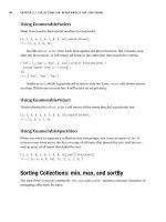
B7 Lubricant biological deterioration
B7.2
Comparison of microbial infections in oil emulsions and straight oils
ECONOMICS OF INFECTION
The total cost of a problem is rarely concerned with the
cost of the petroleum product infected but is made up
from some of the following components:
1 Direct cost of replacing spoiled oil or emulsion.
2 Loss of production time during change and con-
sequential down-time in associated operations.
3 Direct labour and power costs of change.
4 Disposal costs of spoiled oil or emulsion.
5 Deterioration of product performance particularly:
(a) surface finish and corrosion of product in
machining;
(b) staining and rust spotting in steel rolling;
(c) ‘pick-up’ in aluminium rolling.
6 Cost of excessive slime accumulation, e.g. overloading
centrifuges, ‘blinding’ grinding wheels, blocking
filters.
7 Wear and corrosion of production machinery, blocked
pipe-lines, valve and pump failure.
8 Staff problems due to smell and possibly health.
ANTI-MICROBIAL MEASURES
These may involve:
1 Cleaning and sterilising machine tools, pipework, etc.,
between charges.
2 Addition of anti-microbial chemicals to new charges of
oil or emulsion.
3 Changes in procedures, such as:
(a) use of clean or even de-ionised water;
(b) continuous aeration or circulation to avoid
malodours;
(c) prevention of cross-infection;
(d) re-siting tanks, pipes and ducts, eliminating dead
legs;
(e) frequent draining of free water from straight
oils;
(f) change to less vulnerable formulations
4 Continuous laboratory or on-site evaluation of infec-
tion levels.
Physical methods of controlling infection (heat, u.v.,
hard irradiation) are feasible but chemical methods are
more generally practised for metal working fluids. Heat
is sometimes preferred for straight oils. There is no
chemical ‘cure-all’, but for any requirement the follow-
ing important factors will affect choice of biocide.
1 Whether water or oil solubility is required – or both.
2 Speed of action required. Quick for a ‘clean-up’, slow
for preventing re-infection.
3 pH of system – this will affect the activity of the biocide
and, conversely, the biocide may affect the pH of the
system (most biocides are alkaline).
4 Identity of infecting organisms.
5 Ease of addition – powders are more difficult to
measure and disperse than liquids.
6 Affect of biocide on engineering process; e.g. reaction
with oil formulation, corrosive to metals present.
7 Toxicity of biocide to personnel – most care needed
where contact and inhalation can occur – least
potential hazard in closed systems, e.g. hydraulic oils.
8 Overall costs over a period.
9 Environmental impact on disposal.
Most major chemical suppliers can offer one or more
industrial biocides and some may offer an advisory
service.
B8Component performance analysis
B8.1
A useful condition monitoring technique is to check the performance of components, to check that they are performing
their intended function correctly.
COMPONENT PERFORMANCE
The technique for selecting a method of monitoring a component is to decide what function it is required to perform
and then to consider the various ways in which that function can be measured.
Table 8.1 Methods of monitoring the performance of fixed components for fault detection
B8 Component performance analysis
B8.2
Table 8.2 Methods of monitoring the performance of moving components for fault detection
B8Component performance analysis
B8.3
Table 8.3 Methods of monitoring the performance of machines and systems for fault detection
In addition to monitoring the performance of components, it is also useful to monitor the performance of complete
machines and systems.
B9 Allowable wear limits
B9.1
BALL AND ROLLER BEARINGS
If there is evidence of pitting on the balls, rollers or
races, suspect fatigue, corrosion or the passage of
electrical current. Investigate the cause and renew the
bearing.
If there is observable wear or scuffing on the balls,
rollers or races, or on the cage or other rubbing surfaces,
suspect inadequate lubrication, an unacceptable load or
misalignment. Investigate the cause and renew the
bearing.
ALL OTHER COMPONENTS
Wear weakens components and causes loss of efficiency.
Wear in a bearing may also cause unexpected loads to be
thrown on other members such as seals or other bearings
due to misalignment. No general rules are possible
because conditions vary so widely. If in doubt about
strength or efficiency, consult the manufacturer. If in
doubt about misalignment or loss of accuracy, experi-
ence of the particular application is the only sure
guide.
Bearings as such are considered in more detail
below.
JOURNAL BEARINGS, THRUST BEARINGS,
CAMS, SLIDERS, etc.
Debris
If wear debris is likely to remain in the clearance spaces
and cause jamming, the volume of material worn away in
intervals between cleaning should be limited to
1
⁄
5
of the
available volume in the clearance spaces.
Surface treatments
Wear must not completely remove hardened or other
wear resistant layers.
Note that some bearing materials work by allowing
lubricant to bleed from the bulk to the surface. No wear
is normally detectable up to the moment of failure. In
these cases follow the manufacturer’s maintenance
recommendations strictly.
Some typical figures for other treatments are:
Surface condition
Roughening (apart from light scoring in the direction of
motion) usually indicates inadequate lubrication, over-
loading or poor surfaces. Investigate the cause and renew
the bearing.
Pitting usually indicates fatigue, corrosion, cavitation
or the passage of electrical current. Investigate the cause.
If a straight line can be drawn (by eye) across the bearing
area such that 10% or more of the metal is missing due
to pits, then renew the components.
Scoring usually indicates abrasives either in the lubri-
cant or in the general surroundings.
Journal bearings with smoothly-worn
surfaces
The allowable increase in clearance depends very much
on the application, type of loading, machine flexibilities,
importance of noise, etc., but as a general guide, an
increase of clearance which more than doubles the
original value may be taken as a limit.
Wear is generally acceptable up to these limits, subject
to the preceding paragraphs and provided that more
than 50% of the original thickness of the bearing
material remains at all points.
Thrust bearings, cams, sliders, etc. with
smoothly-worn surfaces
Wear is generally acceptable, subject to the preceding
paragraphs, provided that no surface features (for
example jacking orifices, oil grooves or load generating
profiles) are significantly altered in size, and provided
that more than 50% of the original thickness of the
bearing material remains at all points.
CHAINS AND SPROCKETS
For effects of wear on efficiency consult the manu-
facturers. Some components may be case-hardened in
which case data on surface treatments will apply.
CABLES AND WIRES
For effects of wear on efficiency consult the manu-
facturer. Unless there is previous experience to the
contrary any visible wear on cables, wires or pulleys
should be investigated further.
METAL WORKING AND CUTTING TOOLS
Life is normally set by loss of form which leads to
unacceptable accuracy or efficiency and poor surface
finish on the workpiece.
B10Failure patterns and analysis
B10.1
THE SIGNIFICANCE OF FAILURE
Failure is only one of three ways in which engineering
devices may reach the end of their useful life.
In the design process an attempt is usually made to
ensure that failure does not occur before a specified life
has been reached, or before a life limit has been reached
by obsolescence or completion. The occurrence of a
failure, without loss of life, is not so much a disaster, as
the ultimate result of a design compromise between
perfection and economics.
When a limit to operation without failure is accepted,
the choice of this limit depends on the availability
required from the device.
Availability is the average percentage of the time that a
device is available to give satisfactory performance
during its required operating period. The availability of a
device depends on its reliability and maintainability.
Reliability is the average time that devices of a particular
design will operate without failure.
Maintainability is measured by the average time that
devices of a particular design take to repair after a
failure
The availability required, is largely determined by the
application and the capital cost.
FAILURE ANALYSIS
The techniques to be applied to the analysis of the
failures of tribological components depend on whether
the failures are isolated events or repetitive incidents.
Both require detailed examination to determine the
primary cause, but, in the case of repeated failures,
establishing the temporal pattern of failure can be a
powerful additional tool.
Investigating failures
When investigating failures it is worth remembering the
following points:
(a) Most failures have several causes which combine
together to give the observed result. A single cause
failure is a very rare occurrence.
(b) In large machines tribological problems often arise
because deflections increase with size, while in
general oil film thicknesses do not.
(c) Temperature has a very major effect on the perform-
ance of tribological components both directly, and
indirectly due to differential expansions and ther-
mal distortions. It is therefore important to check:
Temperatures
Steady temperature gradients
Temperature transients
Causes of failure
To determine the most probable causes of failure of
components, which exist either in small numbers, or
involve mass produced items the following procedure
may be helpful:
1 Examine the failed specimens using the following
sections of this Handbook as guidance, in order to
determine the probable mode of failure.
2 Collect data on the actual operating conditions and
double check the information wherever possible.
3 Study the design, and where possible analyse its
probable performance in terms of the operating
conditions to see whether it is likely that it could fail by
the mode which has been observed.
4 If this suggests that the component should have
operated satisfactorily, examine the various operating
conditions to see how much each needs to be changed
to produce the observed failure. Investigate each
operating condition in turn to see whether there are
any factors previously neglected which could produce
sufficient change to cause the failure.
Figure 10.1 The relationship between availability,
reliability and maintainability. High availabilities can
only be obtained by long lives or short repair times or
both
B10 Failure patterns and analysis
B10.2
Repetitive failures
Two statistics are commonly used:-
1 MTBF (mean time between failures)
= L
1
+ L
2
+ +L
n
n
where L
1
, L
2
, etc., are the times to failure and n the
number of failures.
2 L
10
Life, is the running time at which the number of
failures from a sample population of components
reaches 10%. (Other values can also be used, e.g. L
1
Life, viz the time to 1% failures, where extreme
reliability is required.)
MTBF is of value in quantifying failure rates, particularly
of machines involving more than one failing component.
It is of most use in maintenance planning, costing and in
assessing the effect of remedial measures.
L
10
Life is a more rigorous statistic that can only be
applied to a statistically homogeneous population, i.e.
nominally identical items subject to nominally identical
operating conditions.
Failure patterns
Repetitive failures can be divided by time to failure
according to the familiar ‘bath-tub’ curve, comprising
the three regions: early-life failures (infantile mortality),
‘mid-life’ (random) failures and ‘wear-out’.
Early-life failures are normally caused by built-in
defects, installation errors, incorrect materials, etc.
Mid-life failures are caused by random effects external
to the component, e.g. operating changes, (overload)
lightning strikes, etc.
Wear-out can be the result of mechanical wear, fatigue,
corrosion, etc.
The ability to identify which of these effects is
dominant in the failure pattern can provide an insight
into the mechanism of failure.
As a guide to the general cause of failure it can be
useful to plot failure rate against life to see whether the
relationship is falling or rising.
Figure 10.2 The failure rate with time of a group of
similar components
Figure 10.3 The failure rate with time used as an
investigative method
B10Failure patterns and analysis
B10.3
Weibull analysis
Weibull analysis is a more precise technique. Its power is
such that it can provide useful guidance with as few as
five repeat failures. The following form of the Weibull
probability equation is useful in component failure
analysis:
F(t) = 1 – exp[␣(t – ␥)

]
where F(t) is the cumulative percentage failure, t the time
to failure of individual items and the three constants are
the scale parameter (␣), the Weibull Index () and the
location parameter (␥).
For components that do not have a shelf life, i.e. there
is no deterioration before the component goes into
service, ␥ = 0 and the expression simplifies to:
F(t) = 1 – exp[␣t

].
The value of the Weibull Index depends on the
temporal pattern of failure, viz:
early-life failures  = 0.5
random failures  =1
wear out  = 3.4
Weibull analysis can be carried out simply and quickly as
follows:
1 Obtain the values of F(t) for the sample size from
Table 10.1
2 Plot the observed times to failure against the appro-
priate value of F(t) on Weibull probability paper
(Figure 10.5).
3 Draw best fit straight line through points.
4 Drop normal from ‘Estimation Point’ to the best fit
straight line.
5 Read off  value from intersection on scale.
For n > 20 – Calculate approximate values of F(t) from
100(i – 0.3)
n + 0.4
where: i is the ith measurement in a sample of n
arranged in increasing order.
Figure 10.4 The relationship between the value of

and the shape of the failure rate curve
Table 10.1 Values of the cumulative per cent failure F(t) for the individual failures in a range of sample sizes
B10 Failure patterns and analysis
B10.4
Figure 10.5 Weibull probability graph paper
B10Failure patterns and analysis
B10.5
Figure 10.6 gives an example of 9 failures of spherical roller bearings in an extruder gearbox. The  value of 2.7 suggests
wear-out (fatigue) failure. This was confirmed by examination of the failed components. The L
10
Life corresponds to a
10% cumulative failure. L
10
Life for rolling bearings operating at constant speed is given by:
L
10
Life (hours) =
10
6
C
x
nP
Where n = speed (rev/min), C = bearing capacity, P = equivalent radial load, x = 3 for ball bearings, 10/3 for roller
bearings.
Determination of the L
10
Life from the Weibull analysis allows an estimate to be made of the actual load. This can be
used to verify the design value. In this particular example, the exceptionally low value of L
10
Life (2500 hours) identified
excessive load as the cause of failure.
Figure 10.6 Thrust rolling bearing failures on extruder gearboxes
B10 Failure patterns and analysis
B10.6
Figure 10.7 gives an example for 17 plain thrust bearing failures on three centrifugal air compressors. The  value of
0.7 suggests a combination of early-life and random failures. Detailed examination of the failures showed that they were
caused in part by assembly errors, in part of machine surges.
Figure 10.7 Plain thrust bearing failures on centrifugal air compressors
B11Plain bearing failures
B11.1
Foreign matter
Characteristics
Fine score marks or scratches in direction of motion,
often with embedded particles and haloes.
Causes
Dirt particles in lubricant exceeding the minimum oil
film thickness.
Foreign matter
Characteristics
Severe scoring and erosion of bearing surface in the line
of motion, or along lines of local oil flow.
Causes
Contamination of lubricant by excessive amounts of dirt
particularly non-metallic particles which can roll
between the surfaces.
Wiping
Characteristics
Surface melting and flow of bearing material, especially
when of low-melting point, e.g. whitemetals, overlays.
Causes
Inadequate clearance, overheating, insufficient oil sup-
ply, excessive load, or operation with a non-cylindrical
journal.
Fatigue
Characteristics
Cracking, often in mosaic pattern, and loss of areas of
lining.
Causes
Excessive dynamic loading or overheating causing reduc-
tion of fatigue strength; overspeeding causing imposition
of excessive centrifugal loading.
B11 Plain bearing failures
B11.2
Fatigue
Characteristics
Loss of areas of lining by propagation of cracks initially at
right angles to the bearing surface, and then progressing
parallel to the surface, leading to isolation of pieces of
the bearing material.
Causes
Excessive dynamic loading which exceeds the fatigue
strength at the operating temperature.
Excessive interference
Characteristics
Distortion of bearing bore causing overheating and
fatigue at the bearing joint faces.
Causes
Excessive interference fit or stagger at joint faces during
assembly.
Fretting
Characteristics
Welding, or pick-up of metal from the housing on the
back of bearing. Can also occur on the joint faces.
Production and oxidation of fine wear debris, which in
severe cases can give red staining.
Causes
Inadequate interference fit; flimsy housing design; per-
mitting small sliding movements between surfaces under
operating loads.
Misalignment
Characteristics
Uneven wear of bearing surface, or fatigue in diagonally
opposed areas in top and bottom halves.
Causes
Misalignment of bearing housings on assembly, or
journal deflection under load.
B11Plain bearing failures
B11.3
Dirty assembly
Characteristics
Localised overheating of the bearing surface and fatigue
in extreme cases, sometimes in nominally lightly loaded
areas.
Causes
Entrapment of large particles of dirt (e.g. swarf),
between bearing and housing, causing distortion of the
shell, impairment of heat transfer and reduction of
clearance (see next column).
Cavitation erosion
Characteristics
Removal of bearing material, especially soft overlays or
whitemetal in regions near joint faces or grooves, leaving
a roughened bright surface.
Causes
Changes of pressure in oil film associated with inter-
rupted flow.
Dirty assembly
Characteristics
Local areas of poor bedding on the back of the bearing
shell, often around a ‘hard’ spot.
Causes
Entrapment of dirt particles between bearing and
housing. Bore of bearing is shown in previous column
illustrating local overheating due to distortion of shell,
causing reduction of clearance and impaired heat
transfer.
Discharge cavitation erosion
Characteristics
Formation of pitting or grooving of the bearing material
in a V-formation pointing in the direction of rotation.
Causes
Rapid advance and retreat of journal in clearance during
cycle. It is usually associated with the operation of a
centrally grooved bearing at an excessive operating
clearance.
B11 Plain bearing failures
B11.4
Cavitation erosion
Characteristics
Attack of bearing material in isolated areas, in random
pattern, sometimes associated with grooves.
Causes
Impact fatigue caused by collapse of vapour bubbles in
oil film due to rapid pressure changes. Softer overlay
(Nos 1, 2 and 3 bearings) attacked. Harder aluminium
–20% tin (Nos 4 and 5 bearings) not attacked under
these particular conditions.
Tin dioxide corrosion
Characteristics
Formation of hard black deposit on surface of white-
metal lining, especially in marine turbine bearings. Tin
attacked, no tin-antimony and copper-tin constituents.
Causes
Electrolyte (sea water) in oil.
Corrosion
Characteristics
Removal of lead phase from unplated copper-lead or
lead-bronze, usually leading on to fatigue of the weak-
ened material.
Causes
Formation of organic acids by oxidation of lubricating
oil in service. Consult oil suppliers; investigate possible
coolant leakage into oil.
‘Sulphur’ corrosion
Characteristics
Deep pitting and attack or copper-base alloys, especially
phosphor-bronze, in high temperature zones such as
small-end bushes. Black coloration due to the formation
of copper sulphide.
Causes
Attack by sulphur-compounds from oil additives or fuel
combustion products.
B11Plain bearing failures
B11.5
‘Wire wool’ damage
Characteristics
Formation of hard black scab on whitemetal bearing
surface, and severe machining away of journal in way of
scab, as shown on the right.
Causes
It is usually initiated by a large dirt particle embedded in
the whitemetal, in contact with journal, especially chro-
mium steel.
Electrical discharge
Characteristics
Pitting of bearing surface and of journal; may cause
rapid failure in extreme cases.
Causes
Electrical currents from rotor to stator through oil film,
often caused by faulty earthing.
‘Wire wool’ damage
Characteristics
Severe catastrophic machining of journal by ‘black scab’
formed in whitemetal lining of bearing. The machining
‘debris’ looks like wire wool.
Causes
Self-propagation of scab, expecially with ‘susceptible’
journals steels, e.g. some chromium steels.
Fretting due to external vibration
Characteristics
Pitting and pick-up on bearing surface.
Causes
Vibration transmitted from external sources, causing
damage while journal is stationary.
B11 Plain bearing failures
B11.6
Overheating
Characteristics
Extrusion and cracking, especially of whitemetal-lined
bearings.
Causes
Operation at excessive temperatures.
Faulty assembly
Characteristics
Localised fatigue or wiping in nominally lightly loaded
areas.
Causes
Stagger at joint faces during assembly, due to excessive
bolt clearances, or incorrect bolt disposition (bolts too
far out).
Thermal cycling
Characteristics
Surface rumpling and grain-boundary cracking of tin-
base whitemetal bearings.
Causes
Thermal cycling in service, causing plastic deformation,
associated with the non-uniform thermal expansion of
tin crystals.
Faulty assembly
Characteristics
Overheating and pick-up at the sides of the bearings.
Causes
Incorrect grinding of journal radii, causing fouling at
fillets.
B11Plain bearing failures
B11.7
Incorrect journal grinding
Characteristics
Severe wiping and tearing-up of bearing surface.
Causes
Too coarse a surface finish, or in the case of SG iron
shafts, the final grinding of journal in wrong direction
relative to rotation in bearing.
Inadequate lubrication
Characteristics
Seizure of bearing.
Causes
Inadequate pump capacity or oil gallery or oilway
dimensions. Blockage or cessation of oil supply.
Inadequate oil film thickness
Characteristics
Fatigue cracking in proximity of a groove.
Causes
Incorrect groove design, e.g. positioning a groove in the
loaded area of the bearing.
Bad bonding
Characteristics
Loss of lining, sometimes in large areas, even in lightly
loaded regions, and showing full exposure of the backing
material.
Causes
Poor tinning of shells; incorrect metallurgical control of
lining technique.
All photographs courtesy of Glacier Metal Co. Ltd
B12 Rolling bearing failures
B12.1
FATIGUE FLAKE
Characteristics
Flaking with conchoidal or ripple
pattern extending evenly across the
loaded part of the race.
Causes
Fatigue due to repeated stressing of
the metal. This is not a fault condi-
tion but it is the form by which a
rolling element bearing should even-
tually fail. The multitude of small
dents are caused by the debris and are
a secondary effect.
ROLLER STAINING
Characteristics
Dark patches on rolling surfaces and
end faces of rollers in bearings with
yellow metal cages. The patches
usually conform in shape to the cage
bars.
Causes
Bi-metallic corrosion in storage. May
be due to poor storage conditions or
insufficient cleaning during manu-
facture. Special packings are avail-
able for severe conditions. Staining,
as shown, can be removed by the
manufacturer, to whom the bearing
should be returned.
EARLY FATIGUE FLAKE
Characteristics
A normal fatigue flake but occurring
in a comparatively short time.
Appearance as for fatigue flake.
Causes
Wide life-expectancy of rolling bear-
ings. The graph shows approximate
distribution for all types. Unless
repeated, there is no fault. If
repeated, load is probably higher
than estimated; check thermal
expansion and centrifugal loads.
BRUISING (OR TRUE
BRINELLING)
Characteristics
Dents or grooves in the bearing track
conforming to the shape of the
rolling elements. Grinding marks not
obliterated and the metal at the edges
of the dents has been slightly raised.
Causes
The rolling elements have been
brought into violent contact with the
race; in this case during assembly
using impact.
ATMOSPHERIC CORROSION
Characteristics
Numerous irregular pits, reddish
brown to dark brown in colour. Pits
have rough irregular bottoms.
Causes
Exposure to moist conditions, use of
a grease giving inadequate protection
against water corrosion.
FALSE BRINELLING
Characteristics
Depressions in the tracks which may
vary from shallow marks to deep
cavities. Close inspection reveals that
the depressions have a roughened
surface texture and that the grinding
marks have been removed. There is
usually no tendency for the metal at
the groove edges to have been dis-
placed.
Causes
Vibration while the bearing is sta-
tionary or a small oscillating move-
ment while under load.
B12Rolling bearing failures
B12.2
FRACTURED FLANGE
Characteristics
Pieces broken from the inner race
guiding flange. General damage to
cage and shields.
Causes
Bad fitting. The bearing was pressed
into housing by applying load to the
inner race causing cracking of the
flange. During running the cracks
extended and the flange collapsed. A
bearing must never be fitted so that
the fitting load is transmitted via the
rolling elements.
INNER RACE SPINNING
Characteristics
Softening and scoring of the inner
race and the shaft, overheating lead-
ing to carbonisation of lubricant in
severe cases, may lead to complete
seizure.
Causes
Inner race fitted with too little inter-
ference on shaft and with light axial
clamping.
OUTER RACE FRETTING
Characteristics
A patchy discoloration of the outer
surface and the presence of reddish
brown debris (‘cocoa’). The race is
not softened but cracks may extend
inwards from the fretted zone.
Causes
Insufficient interference between
race and housing. Particularly notice-
able with heavily loaded bearings
having thin outer races.
SKEW RUNNING MARKS
Characteristics
The running marks on the stationary
race are not parallel to the faces of
the race. In the figure the outer race
is stationary.
Causes
Misalignment. The bearing has not
failed but may do so if allowed to
continue to run out of line.
INNER RACE FRETTING
Characteristics
Heavy fretting of the shaft often with
gross scalloping; presence of brown
debris (‘cocoa’). Inner race may show
some fretting marks.
Causes
Too little interference, often slight
clearance, between the inner race
and the shaft combined with heavy
axial clamping. Axial clamping alone
will not prevent a heavily loaded
inner race precessing slowly on the
shaft.
UNEVEN FATIGUE
Characteristics
Normal fatigue flaking but limited to,
or much more severe on, one side of
the running track.
Causes
Misalignment.