Machinery Component Maintenance and Repair Part 7 pot
Bạn đang xem bản rút gọn của tài liệu. Xem và tải ngay bản đầy đủ của tài liệu tại đây (813.67 KB, 40 trang )
230 Machinery Component Maintenance and Repair
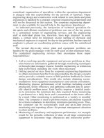
Figure 5-21. Elevation triangles for reverse-indicator alignment example.
Figure 5-22. Plan view triangles for reverse-indicator alignment example.
Figure 5-20 represents the plan view. Here,
Summarizing, we should:
Lower inboard feet 0.003 in.
Lower outboard feet 0.0065 in., say 0.007 in.
Move inboard feet south 0.036in.
Move outboard feet south 0.073in.
These results obviously agree closely with our graphical results. Again,
the same results could have been obtained mathematically. To begin with,
we have to provide a machine sketch, Figure 5-23. Then:
Correction
at
Centerline
Offset Offset
BC
B
Centerline
Inboard at S
Centerline
at A
Offset at S.
=± ±
È
Î
Í
˘
˚
˙
+
Ê
Ë
ˆ
¯
±
0 0185 0 0185 0 0015
12 26
14
0 0729
++
()
+
Ê
Ë
ˆ
¯
= in too far north at outboard feet.
0 0185 0 0185 0 0015
12
14
0 0357
++
()
Ê
Ë
ˆ
¯
= in too far north at inboard feet.
Machinery Alignment 231
Figure 5-23. Machine sketch for reverse-indicator alignment example.
Using numbers from our example:
Again, the answers come out all right if you get the signs right, but the
visualization is difficult unless you make scale drawings or graphical plots
representing the “as found” conditions.
The Graphical Procedure for Reverse Alignment*
As mentioned earlier, the reverse dial indicator method of alignment is
probably the most popular method of measurement, because the dial indi-
cators are installed to measure the relative position of two shaft center-
lines. This section emphasizes this method because of the ease of
graphically illustrating the shaft position.
What Is Reverse Alignment?
Reverse alignment is the measurement of the axis or the centerline of
one shaft to the relative position of the axis of an opposing shaft center-
+-
[]
+
Ê
Ë
ˆ
¯
-= -=-
[]
++
Ê
Ë
ˆ
¯
-=+
-+
[]
+
Ê
Ë
ˆ
¯
+=-+=-
-
0 012 0 007
14 12
14
0 012 0 0093 0 012 0 0027
14 12 26
14
0 12 0 0066
0 0015 0 0185
14 12
14
0 0015 0 0371 0 0015 0 0356
0
. .
.
.
say lower IB 0.003in.
+ 0.012 - 0.007
raise OB 0.007
move IB 0.036 south
in
say in
say in
.
.
0015 0 0185
14 12 26
14
0 0015 0 074 0 0015 0 0725
+
[]
++
Ê
Ë
ˆ
¯
+=-+=-
say in move OB 0.072 or 0.073in. south
Correction
at
Centerline
Offset Offset
BCD
B
Centerline
Outboard at S
Centerline
at A
Offset at S.
=± ±
È
Î
Í
˘
˚
˙
++
Ê
Ë
ˆ
¯
±
232 Machinery Component Maintenance and Repair
* Courtesy of A-Line Mfg., Inc., Liberty Hill, Texas (Tel. 877-778-5454).
line. This measurement can be projected the full length of both shafts for
proper positioning if you need to allow for thermal movement. The mea-
surement also shows the position of the shaft centerlines at the coupling
flex planes, for the purpose of selecting an allowable tolerance. The
centerline measurements are taken in both horizontal and vertical planes
(Figure 5-24).
Learning How to Graph Plot
Graphical alignment is a technique that shows the relative positon of
the two shaft centerlines on a piece of square grid graph paper.
First we must view the equipment to be aligned in the same manner that
appears on the graph plot. In this example we view the equipment with
the “FIXED” on the left and the “MOVABLE” on the right (Figure 5-
25). This remains the same view both vertically and horizontally. Mark
these sign conventions on graph paper, as shown in Figure 5-26.
Example Scale: Each Square ´ = 1.0≤
Scale: Each Square ; = 0.001≤
Next, measure:
A. Distance between indicators
B. Distance between indicator and front foot
C. Distance between feet
Machinery Alignment 233
Figure 5-24. Centerline measurement—both vertical and horizontal.
234 Machinery Component Maintenance and Repair
Figure 5-25. Views of equipment to be aligned.
Figure 5-26. Choose convenient sign convention on graph paper.
The direction of indicator movements is shown in Figure 5-27. Choose
dial indicators that read 0.001-inch (or “one mil”), and become familiar
with the logic of dial indicator sweeps (Figure 5-28). Note that this illus-
tration shows the true arc of measurement. The centerline of the oppos-
ing shaft to be 0.004≤ lower and 0.002≤ to the right of the centerline of
the shaft being measured.
Machinery Alignment 235
Figure 5-27. Direction of indicator movements.
Figure 5-28. Graphical illustration of dial indicator sweep logic. Measurements are made
on coupling rim.
The most important factors to remember about the logic of the dial
indicator sweep are:
1. The plus and minus sign show direction.
2. The number value shows how far (distance).
3. The offset is
1
/
2
the total indicator reading (TIR).
Sag Check
To perform this check (Figure 5-29), clamp the brackets on a sturdy
piece of pipe the same distance they will be when placed on the equip-
ment. Zero both indicators on top, then rotate to bottom. The difference
between the top and bottom reading is the sag.
Sag will always have a negative value, so when allowing for sag on the
vertical move always start with a plus (+) reading.
236 Machinery Component Maintenance and Repair
Figure 5-29. Sag check. Example: 0.002≤ sag. Position indicator to read +2.
Making the Moves
The next step is “making your moves,” as illustrated in Figure 5-30. The
correct account of movement will have been predefined as discussed later
in this segment.
Using the reverse method of centerline measurement, the tolerance
window (Figure 5-31) can be visually illustrated on a piece of square grid
graph paper. Each horizontal square will represent 1 inch, each vertical
square will represent 1 one-thousandth of an inch (0.001≤).
Figure 5-31 shows a typical pump and motor arrangement with the
coupling flex planes 8≤ apart. An allowable tolerance of
1
/
2
thousandths
(0.0005≤) per inch of coupling separation is selected. This is typical for
equipment operating at speeds up to 10,000 rpm. The aligner will now
apply the tolerance window to the graph paper 0.004≤ above and 0.004≤
below the fixed centerline at the same location where the flexing elements
are shown in the figure.
After the adjustment has been made and a new set of indicator readings
have been taken, if the movable centerline stays within the tolerance
window at both flex planes, the alignment is now within tolerance.
Machinery Alignment 237
Figure 5-30. Horizontal and vertical moves explained.
Thermal movement calculations need to be applied to ensure that the
machine can move into tolerance and not move out of tolerance.
It should be noted that the generally accepted value is
1
/
2
thousandths
per inch (0.0005≤) deviation from colinear for each inch of distance
between the coupling flex planes. This is probably too close a tolerance
for general purpose pumps, but is not difficult to obtain. Since unwanted
loads (thermal and other) are difficult to predict, the tighter tolerance gives
a margin of safety.
Summary of Graphical Procedure
Figures 5-32 through 5-38 give a convenient summary of the graphical
procedure.
The “Optimum Move” Alignment Method
At times, as in mixing alcohol with water and measuring volumes, the
whole can be less than the sum of its parts. A parallel situation exists in
(Text continued on page 245)
238 Machinery Component Maintenance and Repair
Figure 5-31. Tolerance window (“tolerance box”).
Machinery Alignment 239
Figure 5-32. Getting set up for the graphical procedure.
240 Machinery Component Maintenance and Repair
Figure 5-33. Preliminary horizontal move.
Machinery Alignment 241
Figure 5-34. Preparing for the vertical move includes soft foot check.
242 Machinery Component Maintenance and Repair
Figure 5-35. Calculate the vertical move.
Machinery Alignment 243
Figure 5-36. Thermal growth considerations, parallel. Thermal movements in machinery
can be graphically illustrated when the aligner knows the precalculated heat movements.
244 Machinery Component Maintenance and Repair
Figure 5-37. Thermal growth considerations, angular.
Machinery Alignment 245
Figure 5-38. Defining the “tolerance box.”
(Text continued from page 238)
the method we are about to illustrate
16
. In effect, we will see that by making
optimum movements of both elements to be aligned, the maximum move-
ment required at any point is a great deal less than if either element were
to be moved by itself. Figure 5-39 shows an electric motor-driven cen-
trifugal pump with severe vertical misalignment. The numbers are actual,
from a typical job, and were not made up for purposes of this text.
As can be seen, regardless of whether we chose to align the motor to
the pump or vice versa, we needed to lower the feet considerably—from
0.111 to 0.484 in. As it happened, the motor feet had only 0.025in. total
shimming, and the pump, as usual, had no shimming at all.
Some would shim the pump “straight up” to get it higher than the motor,
and then raise the motor as required. This, in fact, was first attempted by our
machinists. They had raised the pump about
3
/
8
in., at which point the piping
interfered, and the pump was still not high enough. By inspection of
Figures 5-41 and 5-42 it can be seen that they would have needed to raise it
0.484 in. (or 0.459in. if all outboard motor shims had been removed).
Figure 5-42 shows the solution used to achieve alignment without
radical shimming or milling. As can be seen, our maximum shim addition
was 0.050 in., which is much lower than the values found earlier for
single-element moves. We could have reduced this shimming slightly by
removing our 0.025 in. existing shims from beneath the outboard feet
of the motor, but chose not to do so, leaving some margin for single-
element trim adjustments. As it turned out, the trimming went the other
way, with 0.012 in. and 0.014 in. additions required beneath the motor
inboard and outboard, respectively. This reflects such factors as heel-
and-toe effect causing variation in foot pivot centers. This is normal for
246 Machinery Component Maintenance and Repair
Figure 5-39. Horizontal movement by vertical adjustment: electric motor example.
Figure 5-40. Plotting board solution for electric motor movement exercise of Figure 5-39.
Machinery Alignment 247
Figure 5-41. Motor-pump vertical misalignment with single element move solutions.
situations such as this with short foot centers and long projections to
measurement planes.
Several variations on the foregoing example are worth noting, and are
shown in Figure 5-43. The basic approach is the same for all though, and
is easy to apply once the principle is understood.
We have, to this point, made no mention of thermal growth. If this is
to be considered, the growth data may be superimposed on the basic mis-
alignment plots, or included prior to plotting, before proceeding with the
optimum-move solution. Also, of course, there are valid nongraphical
methods of handling the alignment solutions shown here—but we find the
graphical approach easier for visualization, and accurate enough if done
carefully.
248 Machinery Component Maintenance and Repair
Figure 5-42. Plotting board or graph paper plot showing optimum two-element move.
Machinery Alignment 249
Figure 5-43. Various possibilities in plotting minimum displacement alignment.
Thermal Growth—Twelve Ways to Correct for It
Thermal growth of machines may or may not be significant for align-
ment purposes. In addition, movement due to pipe effects, hydraulic forces
and torque reactions may enter the picture. Relative growth of the two or
more elements is what concerns us, not absolute growth referenced to a
fixed benchmark (although the latter could have an indirect effect if piping
forces are thereby caused). Vibration, as measured by seismic or proxim-
ity probe instrumentation, can give an indication of whether thermal
growth is causing misalignment problems due to differences between
ambient and operating temperatures. If no problem exists, then a “zero-
zero” ambient alignment should be sufficient. Our experience has been
that such zero-zero alignment is indeed adequate for the majority of
electric motor driven pumps. Zero-zero has the further advantage of
simplicity, and of being the best starting point when direction of growth
is unknown. Piping is often the “tail that wags the dog,” causing growth
in directions that defy prediction. For these reasons, we favor zero-zero
unless we have other data that appear more trustworthy, or unless we are
truly dealing with a predictable hot pump thermal expansion situation.
If due to vibration or other reasons it is decided that thermal growth
correction should be applied, several approaches are available, as follows:
1. Pure guesswork, or guesswork based on experience.
2. Trial-and-error.
3. Manufacturers’ recommendations.
4. Calculations based on measured or assumed metal temperatures,
machine dimensions, and handbook coefficient of thermal
expansion.
5. Calculations based on “rules-of-thumb,” which incorporate the
basic data of 4.
6. Shut down, disconnect coupling, and measure before machines
cool down.
7. Same as 6, except use clamp-on jigs to get faster measurements
without having to break the coupling.
8. Make mechanical measurements of machine housing growth
during operation, referenced to baseplate or foundation, or between
machine elements. (Essinger.)
9. Same as 8, except use eddy current shaft proximity probes as the
measuring elements, with electronic indication and/or recording.
(Jackson; Dodd/Dynalign; Indikon.)
10. Measure the growth using precise optical instrumentation.
11. Make machine and/or piping adjustments while running, using
vibration as the primary reference.
250 Machinery Component Maintenance and Repair
12. Laser measurement represents another possibility. The OPTA-
LIGN
®
method mentioned earlier also covers hot alignment checks.
Let us now examine the listed techniques individually.
Guesswork. Guesswork is rarely reliable. Guesswork based on experi-
ence, however, may be quite all right—although perhaps in such cases it
isn’t really guesswork. If a certain thermal growth correction has been
found satisfactory for a given machine, often the same correction will
work for a similar machine in similar service.
Trial-and-Error. Highly satisfactory, if you have plenty of time to experi-
ment and don’t damage anything while doing so. Otherwise, to be avoided.
Manufacturers’ Recommendations. Variable. Some will work well, others
will not. Climatic, piping, and process service differences can, at times,
change the growth considerably from manufacturers’ predictions based on
their earlier average experience.
Calculations Based on Measured or Assumed Metal Temperatures, Machine
Dimensions, and Handbook Coefficients of Thermal Expansion.
Again,
results are variable. An infrared thermometer is a useful tool here, for
scanning a machine for temperature. This method ignores effects due to
hydraulic forces, torque reactions, and piping forces.
Calculations Based on Rules of Thumb. Same comment as previous
paragraph.
Shut Down, Disconnect Coupling, and Measure before Machines Cool Down.
About all this can be expected to do is give an indication of the credulity
of the person who orders it done. In the time required to get a set of mea-
surements by this method, most of the thermal growth and all of the torque
and hydraulic effect will have vanished.
Same as Previous Paragraph Except Use Clamp-On Jigs to Get Faster Mea-
surements Without Having to Break the Coupling.
This method, used in
combination with backward graphing, should give better results than 6,
but how much better is questionable. Even with “quick” jigs, a major part
of the growth will be lost. Furthermore, shrinkage will be occurring during
the measurement, leading to inconsistencies. Measurement of torque and
hydraulic effects will also be absent by this method. Some training courses
advocate this technique, but we do not. If used, however, three sets of data
should be taken, at close time intervals—not two sets as some texts rec-
Machinery Alignment 251
ommend. The cooling, hence shrinkage, occurs at a variable rate, and three
points are required to establish a curve for backward graphing.
Make Mechanical Measurements of Machine Housing Growth During Oper-
ation, Referenced to Baseplate or Foundation, or Between Machine Ele-
ments.
This method can be used for machines with any type of coupling,
including continuous-lube. Essinger
5
describes one variation, using base-
plate or foundation reference points, and measurement between these and
bearing housing via a long stroke indicator having Invar 36 extensions
subject to minimum expansion-contraction error. Hot and cold data are
taken, and a simple graphic triangulation method gives vertical and hori-
zontal growth at each plane of measurement. This method is easy to use,
where physical obstructions do not prevent its use. Bear in mind that base
plate thermal distortion may affect results. It is reasonably accurate, except
for some machines on long, elevated foundations, where errors can occur
due to unequal growth along the foundation length. In such cases, it may
be possible to apply Essinger’s method between machine cases, without
using foundation reference points. A further variation is to fabricate brack-
ets between machine housings and use a reverse-indicator setup, except
that dial calipers may be better than regular dial indicators which would
be bothered by vibration and bumping.
Same as Previous Paragraph, But Use Eddy Current Shaft Proximity Probes
as the Measuring Elements, with Electronic Indicating and/or Recording.
Excepting the PERMALIGN
®
method, this one lends itself the best to
keeping a continuous record of machine growth from startup to stabilized
operation. Due to the complexity and cost of the instrumentation and its
application, this technique is usually reserved for the larger, more complex
machinery trains. Judging by published data, the method gives good
results, but it is not the sort of thing that the average mechanic could be
fully responsible for, nor would it normally be justified for an average,
two-element machinery train. In some cases, high machine temperatures
can prevent the use of this method. The Dodd bars offer the advantage
over the Jackson method that cooled posts are not needed and thermal dis-
tortion of base plate does not affect results. The Indikon system also has
these advantages, and in addition can be used on unlimited axial spans. It
is, however, more difficult to retrofit to an existing machine.
Measure the Growth Using Precise Optical Instrumentation. This method
makes use of the precise tilting level and jig transit, with optical microm-
eter and various accessories. By referencing measurements to fixed ele-
vations or lines of sight, movement of machine housing points can be
determined quite accurately, while the machine is running. As with the
252 Machinery Component Maintenance and Repair
previous method, this system is sophisticated and expensive, with delicate
equipment, and requires personnel more knowledgeable than the average
mechanic. It is therefore reserved primarily for the more complex machin-
ery trains. It has given good results at times, but has also given erroneous
or questionable data in other instances. The precise tilting level has
additional use in soleplate and shaft leveling, which are not difficult to
learn.
Several consultants offer optical alignment services. For the plant
having only infrequent need for such work, it is usually more practical to
engage such a consultant than to attempt it oneself.
Make Machine and/or Piping Adjustments While Running, Using Vibration
as the Primary Reference.
Baumann and Tipping
2
describe a number of
horizontal onstream alignments, apparently made with success. Others are
reluctant to try such adjustments for fear of movement control loss that
could lead to damage. We have, however, frequently adjusted pipe sup-
ports and stabilizers to improve pump alignment and reduce vibration
while the pump was running.
Laser Measurements
With the introduction of the modern, up-to-date PERMALIGN
®
system, laser-based alignment verification has been extended to cover hot
alignment checks. Figure 5-44 illustrates how the PERMALIGN
®
is
mounted onto both coupled machines to monitor alignment. The mea-
surements are then taken when the monitor (shown mounted on the left-
hand machine) emits a laser beam, which is reflected by the prism
mounted on the other machine (shown on the right). The reflected beam
reenters the monitor and strikes a position detector inside. When either
machine moves, the reflected beam moves as well, changing its position
in the detector. This detector information is then processed so that the
amount of machine movement is shown immediately in terms of
1
/
100
mm
or mils in the display, located directly below the monitor lens. Besides
displaying detector X and Y co-ordinates, the LCD also indicates system
temperature and other operating information.
Thermal Growth Estimation by Rules of Thumb
We will now describe several “rules of thumb” for determining growth.
Frankly, we have little faith in any of them, but are including them here
for the sake of completeness.
Machinery Alignment 253
The following is for “foot-mounted horizontal, end suction centrifugal
pumps driven by electric motors”:
For liquids 200°F and below, set motor shaft at same height as pump
shaft.
254 Machinery Component Maintenance and Repair
Figure 5-44. Hot alignment of operating
machines being verified by laser-optic
means (courtesy Prüftechnik A.G., Ismaning,
Germany).