Practical Pediatric Gastrointestinal Endoscopy - part 1 pps
Bạn đang xem bản rút gọn của tài liệu. Xem và tải ngay bản đầy đủ của tài liệu tại đây (556.59 KB, 22 trang )
Practical
Pediatric
Gastrointestinal
Endoscopy
To my life muse, my wife Irina, my talented
daughter Zhenya, and in memory of my
remarkable parents.
George Gershman
Practical
Pediatric
Gastrointestinal
Endoscopy
George Gershman
Associate Professor of Pediatrics
David Geffen School of Medicine
Chief, Division of Pediatrics Gastroenterology and Nutrition
HARBOUR-UCLA Medical Center
Torrance, California, USA
Marvin Ament
Professor of Pediatrics
David Geffen School of Medicine
Chief, Division of Pediatric Gastroenterology and Nutrition
UCLA Medical Center
Los Angeles, California, USA
C
2007 by Blackwell Publishing Ltd
Blackwell Publishing, Inc., 350 Main Street, Malden, Massachusetts 02148-5020,
USA
Blackwell Publishing Ltd, 9600 Garsington Road, Oxford OX4 2DQ, UK
Blackwell Publishing Asia Pty Ltd, 550 Swanston Street, Carlton, Victoria 3053,
Australia
The right of the Authors to be identified as the Authors of this Work has been
asserted in accordance with the Copyright, Designs and Patents Act 1988.
All rights reserved. No part of this publication may be reproduced, stored in a
retrieval system, or transmitted, in any form or by any means, electronic,
mechanical, photocopying, recording or otherwise, except as permitted by the UK
Copyright, Designs and Patents Act 1988, without the prior permission of the
publisher.
First published 2007
1 2007
Library of Congress Cataloging-in-Publication Data
Gershman, George.
Practical pediatric gastrointestinal endoscopy / George Gershman,
Marvin Ament.
p. ; cm.
Includes bibliographical references and index.
ISBN-13: 978-1-4051-3193-3
ISBN-10: 1-4051-3193-4
1. Pediatric gastroenterology—Endoscopic surgery.
I. Ament, Marvin Earl, 1938– II. Title.
[DNLM: 1. Endoscopy, Gastrointestinal. 2. Pediatrics—methods.
3. Child. WI 141 G381p 2006]
RJ446.G47 2006
618.92
3307545—dc22 2006013734
A catalogue record for this title is available from the British Library
Set in 9/11.5 Palatino and Univers by TechBooks, India
Printed and bound in Singapore by Markono Print Media Pte Ltd
Commissioning Editor: Alison Brown
Editorial Assistant: Jennifer Seward
Development Editor: Adam Gilbert
Production Controller: Kate Charman
For further information on Blackwell Publishing, visit our website:
The publisher’s policy is to use permanent paper from mills that operate a
sustainable forestry policy, and which has been manufactured from pulp
processed using acid-free and elementary chlorine-free practices. Furthermore,
the publisher ensures that the text paper and cover board used have met
acceptable environmental accreditation standards.
v
Contents
Contributors, viii
1 Introduction, 1
2 Settings and Staff, 2
The endoscopy unit, 2
Pediatric endoscopy nurse, 3
Disinfections of the endoscopes and accessories, 4
Documentation, 4
Further reading, 5
3 Equipment, 6
Overview, 6
Insertion tube, 6
Video image capture, 16
“Reading’’ the image created on the CCD, 18
Types of CCDs, 20
History of endoscope CCD development, 21
Shape of displayed image, 22
Reproduction of color, 23
Reproduction of motion, 32
Transillumination, 33
Laser therapy with video endoscopes, 33
Image resolution, 34
Color reproduction accuracy, 35
Troubleshooting, 35
Endoscope reprocessing, 35
Summary, 43
Further reading, 43
4 Patient Preparation, 45
Pediatric-monitored sedation and anesthesia for
diagnostic and therapeutic
procedures in endoscopy, 46
During sedation, 51
Postsedation care, 52
Specific sedation techniques, 52
Further reading, 57
vi CONTENTS
5 Diagnostic Upper Endoscopy
Technique, 60
Preparation for esophageal intubation, 60
Assembling the equipment and preprocedure
checkup, 61
Endoscope handling, 62
Technique of esophageal intubation, 63
Indications for upper endoscopy, 77
Push enteroscopy/jejunoscopy, 94
Further reading, 97
6 Therapeutic Upper GI
Endoscopy, 102
Benign esophageal stricture, 102
Pneumatic dilation in achalasia, 103
Foreign bodies, 105
Endoscopic hemostasis, 109
Percutaneous endoscopic gastrostomy, 117
Nasojejunal tube placement, 125
Further reading, 127
7 Pediatric Colonoscopy, 132
Introduction, 132
Indications for colonoscopy, 132
Preparation of the patient for colonoscopy, 134
Equipment, 137
Magnetic imaging system, 138
Informed consent and preprocedure preparation, 139
Sedation for colonoscopy, 139
Embryology of the colon, 140
Endoscopic anatomy, 142
Torque-steering technique, 147
Exploration of the sigmoid colon and
sigmoid–descending junction, 152
Splenic flexure and transverse colon, 154
Hepatic flexure, ascending colon, and cecum, 155
Terminal ileum, 156
Complications, 157
Common pathology, 159
Further reading, 168
8 Polypectomy, 171
Basic principles of electrosurgery, 171
Snare loops, 173
Polypectomy routine, 175
Safety routine, 175
Safety conditions and techniques, 176
CONTENTS vii
Complications, 180
Further reading, 180
9 Chromoendoscopy, 181
Indications, 181
Application technique, 184
Recognition of the lesions, 189
Further reading, 193
10 Wireless Capsule Endoscopy, 194
History, 194
The GIVEN M2A system, 194
Localization, 195
Suspected blood indicator, 196
Indication for use, 196
Diagnostic yield, 196
Contraindications to capsule endoscopy, 197
Pacemaker safety, 197
Bowel preparation, 197
Promotility agents, 198
Endoscopic assistance, 198
Complications, 198
Outcome of capsule endoscopy, 198
Pediatric patients, 198
Further reading, 199
Index, 201
viii
Contributors
David Barlow
Vice-President Research and
Development Olympus America Inc.,
Center Valley, PA (Chapter 3;
Equipment)
Judith Brill
Professor of Pediatrics and
Anesthesiology, Chief, Division of
Pediatric Critical Care, UCLA
Medical Center, Geffen School of
Medicine, Los Angeles, CA,
(Chapter 4; Pediatric-monitored
sedation and anesthesia for
diagnostic and therapeutic
procedures in endoscopy)
Marsha Kay
Department of Pediatric
Gastroenterology and Nutrition,
Cleveland Clinic Foundation,
Cleveland, OH, (Chapter 6;
Percutaneous endoscopic
gastrostomy)
Alberto Ravelli
Gastroenterology and Hepatology
Service, University Department of
Pediatrics, Children’s Hospital,
Spedali Civili, Brescia, Italy
(Chapter 9)
Jorge Vargas
Professor of Pediatrics, Division of
Pediatric Gastroenterology,
Hepatology and Nutrition, UCLA
Medical Center, Geffen School of
Medicine, Los Angeles, CA,
(Chapter 6; Endoscopic hemostasis)
Robert Wyllie
Chairman, Department of Pediatric
Gastroenterology and Nutrition
Cleveland Clinic Foundation,
Cleveland, OH, (Chapter 6;
Percutaneous endoscopic
gastrostomy)
1
1
Introduction
In the late 1960s and early 1970s, sporadic attempts to per-
form esophagogastroduodenoscopy (EGD) using fiberscopes
designed for adults were made in children. However, the ac-
tual “birth’’ of pediatric EGD occurred a few years later when
prototypes of pediatric flexible gastroscopes and panendoscopes
became commercially available. Subsequently, the pediatric
community received unequivocal evidence of very low rates of
complications related to upper gastrointestinal (GI) endoscopy,
high diagnostic yields, cost-effectiveness due to safe use of the
procedure in outpatient settings, and the ability to perform a va-
riety of therapeutic procedures successfully adopted from adult
GI practice. This led to widespread use of EGD in pediatrics.
Flexible GI endoscopy is a unique method of investigation of
the GI tract in real time. It links direct observation of the ob-
ject, with or without magnification and application of different
dyes, with target biopsy, ultrasound technique, and variety of
therapeutic procedures. It is an invasive procedure by definition.
When applied to pediatric patients, safety becomes a major prior-
ity. In order to minimize morbidity associated with pediatric GI
endoscopy, the endoscopist,especiallythe beginner, shouldlearn
all technical aspects of the procedure including the following:
r
Endoscopic equipment such as endoscopes, light sources,
biopsy forceps, snares, graspers, needles, electrosurgical de-
vices, and all other accessories.
r
Appropriate setting of the endoscopic equipment and doses
of commonly used medications and solutions such as
epinephrine, glucagon, and sclerosing agents.
r
Proper techniques of diagnostic and therapeutic procedures.
The endoscopist should also become familiar with age-related
anatomic variations of the GI tract and specific responses of the
central nervous system, respiratory, and cardiovascular systems
to artificial conditions created by the procedure itself. These in-
clude intubations of the esophagus, increased intra-abdominal
pressure, elevation of the diaphragm, and stretching of the
mesentery.
Practical Pediatric Gastrointestinal Endoscopy
George Gershman, Marvin Ament
Copyright © 2007 by Blackwell Publishing Ltd
2
2
Settings and Staff
THE ENDOSCOPY UNIT
Pediatric gastrointestinal (GI) endoscopy can be performed in an
inpatient or outpatient endoscopy unit, at the patient’s bedside,
and in the operating room.
The endoscopy unit is usually designated for elective proce-
dures. Typically, it has five functional areas:
r
The preprocedure area consists of two major spaces:
One is a dedicated waiting and reception area.
The other serves as a space where parental consent can be
obtained, the patient can be undressed and examined, and
intravenous (IV) access may be established.
r
Procedure area with examining rooms
r
Recovery area
r
Staff area with a work station for units with more than three
rooms
r
Storage space and a section dedicated to cleaning and disin-
fections of endoscopes.
Except in children’s hospitals, the volume of pediatric pro-
cedure is usually not enough to run a separate endoscopic
GI unit. Frequently, pediatric GI procedures must be sched-
uled and performed in the endoscopy unit shared with adult
gastroenterologists.
Endoscopy units that are shared between pediatric and adult
gastroenterologists must have a nursing and ancillary support-
ing staff that is comfortable and trained to work with both chil-
dren and adults. They must recognize the difference in the needs
of the patients. Although some units that serve both adults and
children may dedicate a special room for pediatric patients, it is
far more flexible for all rooms to be equipped to work with both
children and adults.
Most pediatric bedside endoscopy is done in intensive care
units because of the critical state of the patients. Bedside pedi-
atric endoscopy is typically limited to children with acute GI
bleeding or complicated recovery after bone-marrow or solid
organ transplantation, those who are in isolation, admitted to
pediatric, neonatal intensive care units, or pediatric emergency
department. It is usually a complex and labor-intensive proce-
dure in critically ill patients, which requires
1 full cooperation between skilled endoscopist, residents, en-
doscopy nurses, and attending pediatric physician or intensivist;
Practical Pediatric Gastrointestinal Endoscopy
George Gershman, Marvin Ament
Copyright © 2007 by Blackwell Publishing Ltd
SETTINGS AND STAFF 3
2 good functional conditions of all endoscopic equipment;
3 a well-organized and appropriately equipped mobile en-
doscopy station.
The mobile station should be loaded with a light source, elec-
trosurgical unit, biopsy forceps, retractable needles, polypec-
tomy snares, graspers, rubber bands, epinephrine, sclerosants,
different sizes bite-guards, biopsy mounting sets, fixatives, cul-
ture media, cytology brushes, and slides. The bedside area
should be spacious enough to accommodate the endoscopic sta-
tion, a portable monitor, and equipment for general anesthesia.
Two separate suction canistersshould be available for endoscopy
and oral or tracheal aspiration.
The position of the bed should be adjusted for the height of the
endoscopist and special indication for the procedure; for exam-
ple, reverse Trendelenburg position is advantageous for patients
with acute GI bleeding to reduce the risk of aspiration and to
improve visibility of the cardia and subcardia areas in children
with stress ulcer, which is not uncommon after neuro- or cardiac
surgery. A similar position may be useful for patients with GI
bleeding due to portal hypertension and gastric varices. Endo-
scopic procedures in the neonatal intensive care unit should be
performed under a warmer.
Pediatric GI endoscopy in the operating room is restricted to
children with obscure GI bleeding, Peutz-Jeghers syndrome, or
other circumstances, which require intraoperative enteroscopy
or precise localization of the gastrointestinal lesions or assistance
during surgery; for example, a placement of the string for retro-
grade bouginage of esophageal stricture. The endoscopy team
should be familiar with the operating room environment and
regulations.
PEDIATRIC ENDOSCOPY NURSE
A well-trained nurse is the key to a successful pediatric en-
doscopy team. This individual should be skilled in many areas
such as:
1 How to communicate with the parents and the child in or-
der to decrease the degree of stress and anxiety before the
procedure;
2 Knowing how to establish and secure IV access before and, if
necessary, during the procedure;
3 Preparing of all monitoring devices including EKG leads,
pulse oximeter sensors, blood pressure cuffs appropriate for the
child’s size, and life support equipment such as nasal cannulas,
proper size oxygen masks, ambu-bags, and intubation tray;
4 Selecting and preparing appropriate endoscopic equipment
for the procedure;
4 CHAPTER 2
5 Knowing how to monitor patients during sedation, proce-
dure, and recovery;
6 Knowing how to properly mount the biopsy specimens and
preparation of the cytological slides;
7 Being skillful in mechanical and chemical cleansing of the
equipment and disinfection of the working space;
8 Quality control maintenance.
It is a great help to have such a nurse on call 24 hours a day.
DISINFECTIONS OF THE ENDOSCOPES
AND ACCESSORIES
Thorough mechanical cleaning of the endoscope and nondis-
posable instruments is an essential part of any procedure, but
especially a bedside endoscopy. It is an important initial phase
of disinfection and also quite an effective preventive measure
against clogging of the air/water channel and future mechanical
failure of very expensive endoscopes. The final cleaning of the
instruments is usually performed with glutaraldehyde, which
destroys viruses and bacteria within a few minutes. Endoscopes
are allowed to soak typically for a 20-minute period, although
high-risk situations including known or suspected mycobacte-
rial infection may require longer periods of time. The chemical
itself can exacerbate reactive airway disease, asthma, or dermati-
tis in predisposed patients or staff. For this reason, instruments
are thoroughly rinsed in water and allowed to dry prior to their
next use. Air/water and suction channels are further rinsed in a
solution containing 70% alcohol and also require compressed air
drying to prevent bacterial growth. Instruments should be hung
and stored in a vertical position in a well-ventilated cupboard to
ensure dryness and minimize chance of bacterial growth.
More detailed description of disinfection technique is pre-
sented in Chapter 3.
DOCUMENTATION
Different types of photodocumentation are available during en-
doscopy. The films or Polaroid photographs of the findings seen
at endoscopy have been replaced with digital photo printers in
early 1990s. A real-time videotaping is the least practical but cur-
rently the cheapest method. It used to be popular for teaching
purpose. Although a digital transformation of VHS recording
into the laser disk with subsequent snapshot images is now fea-
sible, it is going to be replaced soon with DVD recorders specif-
ically designed for endoscopic procedures.
A modern digital file system allows the endoscopist to store
and print quality digital prints on a regular paper, although such
equipment is costly and not routinely available. It also allows
SETTINGS AND STAFF 5
one to generate the report of just-completed procedures and
supplement the medical chart with important descriptive and
visual information.
FURTHER READING
AGA. The American gastroenterological association standards for office-
based gastrointestinal endoscopy services. Gatsroenterology 2001;121:
440–3.
Berg JW, Appelbaum PS, Lidz CW, Parker LS. Informed Consent: Legal
Theory and Clinical practice. Oxford: Oxford University Press; 2001.
Braddock CH, Fihn SD, Levinson W, Johnson AR, Pearlman RA. How
doctors and patients discuss routine clinical decisions: informed deci-
sion making in the outpatient setting. J Gen InternMed 1997;12:339–45.
Foote MA. The role of gastrointestinal assistant. In: Sivak MV (series ed),
Gastrointestinal Endoscopy Clinics of North America. Philadelphia,
PA: WB Saunders; 1994:523–39.
Recommended practices for managing the patient receiving moderate
sedation/analgesia. AORN J 2002;75:649–52.
SGNA guidelines for nursing care of the patient receiving sedation
and analgesia in the gastrointestinal endoscopy setting. Gastroenterol
Nurs 2000;23:125–9.
Sivak KM. Gastroenterological Endoscopy, Vol 1, 2nd edn. Philadelphia,
PA: WB Saunders; 2000.
Society of Gastroenterology Nurses and Associates, Inc. Guidelines for
documentations in the gastrointestinal endoscopy setting. Gastroen-
terol Nurs 1999;22:69–97.
Society of Gastroenterology Nurses and Associates, Inc. Role delineation
of the registered nurse in a staff position in gastroenterology. Position
statement. Gastroenterol Nurs 2001;24:202–3.
Waye JD, Rich M. Planning an Endoscopy Suite for Office and Hospital.
New York: Igaki-Shoin Medical Publisher; 1990.
6
3
Equipment
OVERVIEW
The modern video endoscope is the result of more than two
decades of refinements in solid-state imaging technology and
mechanical design. The basic shape, controls, and method of use
are relatively unchanged from fiberoptic endoscopes used in the
mid-1970s. Although alternative designs for the control section
have been proposed (e.g., “pistol-grip’’controls), the basic layout
of the gastrointestinal (GI) endoscope is similar across all mod-
els (gastroscopes, colonoscopes, etc.) and all manufacturers. The
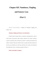
basic components and controls of the video endoscope are illus-
trated in Fig. 3.1. The instrument is designed to be held and oper-
ated by the endoscopist’s left hand, while the endoscopist’s right
hand primarily controls the insertion tube – pushing, torquing,
advancing, and withdrawing as necessary.
INSERTION TUBE
Although the control sectionof various endoscope models is sim-
ilar, it is primarily the length and flexibility of the insertion tube
that distinguishes a gastroscope from a colonoscope, and it is the
physical dimensions of the insertion tube (outer diameter, chan-
nel diameter, etc.) that distinguishes one model of endoscope
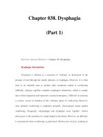
from another. Figure 3.2 illustrates the internal components of a
typical videoscope insertion tube. Both gastroscopes and colono-
scopes employ similar components. While the insertion tube’s
outward appearance is deceptively plain, internally it is filled
with a collection of tubes, control wires, electrical wires, glass
fibers, and other components. The largest internal tube housed
in the insertion tube is typically the instrument “channel’’ and
is used for suctioning fluid and taking biopsies. Smaller internal
tubes are used to convey air and water for insufflation and lens
washing, respectively. Some models, more often colonoscopes,
have an additional forward water-jet tube for washing the lu-
men wall. As Fig. 3.2 illustrates, four angulation control wires
run the length of the insertion tube. These are used to control
the deflection of the distal tip. A group of very fine electrical
wires connects the CCD (charge-coupled device) image sensor
at the distal tip of the endoscope to the video processor. These
wires are housed in a protective sheath to prevent them from
being damaged as the instrument is manipulated. One or two
Practical Pediatric Gastrointestinal Endoscopy
George Gershman, Marvin Ament
Copyright © 2007 by Blackwell Publishing Ltd
Biopsy
valve
Air/water valve
Suction valve
Remote switches
Insertion
tube
Bending
section
Distal tip
Insertion tube
stiffness
control
Channel
opening
Control
section
R/L angulation
lock
R/L angulation
knob
U/D angulation
lock
U/D angulation
knob
Boot
One-way
valve
Vent hole
Suction
connector
Air supply
connector
Water supply
connector
Universal
cord
Connection to
video processor
Air pipe
Light guide
Quartz lens
Light source
connector
Fig. 3.1 Colonoscope – components and controls. Gastroscopes have a similar construction.
Fig. 3.2 Insertion tube – internal components and construction.
8 CHAPTER 3
bundles of delicate glass fibers also run the length of the inser-
tion tube, bringing light from the light source to the distal end
of the endoscope. These fragile fiberoptic bundles also require
protection and are enclosed in a soft flexible protective sheath.
Colonoscopes with adjustable insertion tube flexibility have an
additional component – a tensioning wire to control insertion
tube stiffness.
The endoscope designer mustpack all of these individual com-
ponents into the smallest possible cross-sectional area in order to
minimize the outer diameter of the insertion tube. A small inser-
tion tube diameter is especially important in instruments used
in pediatric endoscopy, but the components cannot be packed
too tightly. The endoscope designer must plan for enough free
space to permit the components to move about without dam-
aging the more fragile components (e.g., CCD wires, fiberoptic
strands) as the instrument is torqued and flexed during use. A
dry powdered lubricant is applied to all internal components
to reduce the frictional stress they place on each other during
insertion tube manipulation.
Manufacturers typically advise that to avoid damage the en-
doscope should not be coiled tighter than a specific radius during
use, reprocessing, and storage. Although overcoiling of the inser-
tion tube may cause damage, more frequent causes of insertion
tube damage are accidental crushing of the tube (e.g., patient
bite, accidental closure in the carrying case hinge) and kinking
at the boot where the insertion tube joins the control section (see
Fig. 3.1).
Insertion tube flexibility
The handling characteristics of the insertion tube are extremely
important. For ease of insertion, the instrument must be capable
of accurately transmitting torque from one end of the tube to the
other. Any rotation applied by the endoscopist to the proximal
portion of the shaft must be transferred to the distal tip of the
instrument in a 1:1 ratio. In order to transmit this torque and
prevent the instrument shaft from simply twisting up, the inser-
tion tube is built around several flat, spiral metal bands that run
just under the skin of the insertion tube (see Fig. 3.2). Because
these helical bands are wound in opposite directions, they lock
against one another as the tube is torqued, accurately transmit-
ting rotation of the proximal end of the tube to the distal end of
the tube. At the same time, the gaps in the helical bands allow
the shaft to flex freely. These metal bands also give the insertion
tube its round shape and help prevent the internal components
of the insertion tube from being crushed by external forces.
The helical bands are covered by a layer of fine stainless steel
wire that has been braided into a tubular mesh. This mesh creates
EQUIPMENT 9
a metal, fabric-like layer, which covers the sharp edges of the
spiral bands, and creates a continuous surface upon which the
outer layer of the tube can be applied. The external layer (ob-
servable to the user) is composed of a plastic polymer, typically
black or dark green, which is extruded over the wire mesh to
create a smooth outer surface for the insertion tube. The poly-
mer layer provides an atraumatic, biocompatible, and water-
tight exterior for the insertion tube. It is usually marked with
a scale to allow the endoscopist to gauge the depth of insertion.
While each component of the insertion tube has some effect on
the overall flexibility of the tube, the endoscope designer most
often adjusts the construction of the wire mesh and the outer
polymer layer to fine-tune the handling characteristics of the
instrument.
Years of experience have shown that a more rigid insertion
tube is optimal for examining the fixed anatomy of the upper GI
tract. On the other hand, the colon, with its tortuosity and freely
moving loops, is best examined by a more flexible instrument.
Therefore, if one were to compare a colonoscope and a gastro-
scope side by side, one would find that overall the colonoscope
insertion tube is much more flexible.
The ideal colonoscope insertion tube has to be flexible, yet
highly elastic, and sufficiently floppy (nonrigid) to conform eas-
ily to the tortuous anatomy of the patient. It should not exert
undue force on the colon or its attached mesentery. On the other
hand, the instrument should have sufficient column strength to
prevent buckling when the proximal end of the instrument is
pushed. (In contrast, a wet noodle, which is also extremely flex-
ible, has no column strength and collapses when pushed.) In
addition to its flexibility, the colonoscope should have sufficient
elasticity to pop back into a straightened condition whenever it is
pulled back. This aids the endoscopist in removing colon loops.
The goal in designing the proximal portion of the insertion tube,
therefore, is to prevent the reformation of bowel loops as the
instrument is advanced. Obtaining the best combination of flexi-
bility, elasticity, column strength, and torqueability is the art and
science of insertion tube design. Often times, improvements in
one of these characteristics negatively impact one or more of the
others. The final design is usually a compromise of these ideal
characteristics, confirmed by months of clinical testing.
To improve the ability to insert both gastroscopes and colono-
scopes, the flexibility of the insertion tube typically varies
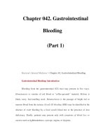
throughout its length. As Fig. 3.3 illustrates, the distal 40 cm of
the colonoscope insertion tube is significantly more flexible than
the proximal portion of the tube. This variation in flexibility from
proximal end to distal end is achieved by changing the formula-
tion of the tube’s outer polymer layer as it is extruded over the
underlying wire mesh during the manufacturing process. The
10 CHAPTER 3
Fig. 3.3 The flexibility of the colonoscope insertion tube varies over its length. On some models it can be
further stiffened by changing the setting on the adjustable stiffness control.
extrusion machine that manufactures the outer coating of the
insertion tube contains two types of plastic resins, one signif-
icantly harder than the other. Initially, as the distal end of the
insertion tube passes through the machine, a layer of soft resin
is applied to distal 40 cm of the insertion tube. This soft resin
is gradually replaced by the hard resin within a transition zone
(T-zone in Fig. 3.3) near the middle of the tube. The remaining
proximal portion of the insertion tube (50–160 cm) is constructed
totally from the hard resin (Moriyama 2000). The end result is
a colonoscope insertion tube that has a soft distal portion for
atraumatically snaking through a tortuous colon, with a stiffer
proximal portion that is effective at preventing loop reformation
in those portions of the colon that have already been straightened
by the instrument. The flexibility of a gastroscope’s insertion also
varies in a similar manner – being more flexible at the distal end
and stiffer at the proximal end.
Clinical experience has shown that endoscopists may disagree
over what constitutes an insertion tube with “ideal’’ physical
characteristics. This may be due to the differences in the endo-
scopist’s training, insertiontechnique, and past experience.In ad-
dition, some endoscopists have expressed a desire to change the
characteristics of the insertion tube during the procedure itself,
based on insertion depth or the patient’s anatomy. This has led
to the development of an insertion tube with adjustable stiffness
(Moriyama 2001). Colonoscopes with adjustable stiffness have a
tensioning wire that runs the length of the insertion tube (see Fig.
3.2). The amount of tension in this wire is controlled by rotating
a ring at the proximal end of the insertion tube, just below the
control section (see Fig. 3.1). When the inner wire in the stiffening
system is in the “soft’’ position, the stiffening system provides no
additional stiffness to the insertion tube beyond that provided
by the wire mesh and polymer coat. When the control ring is ro-
tated to one of the “hard’’ positions, the pull wire is retracted and
EQUIPMENT 11
placed under heavy tension. This stiffens the coil wire surround-
ing the pull wire and adds significant rigidity to the insertion
tube. As Fig. 3.3 summarizes, the base stiffness of the insertion
tube (Setting = 0) is established by varying the mixture of hard
and soft resins in the outer polymer coat of the insertion tube.
This base stiffness, however, can be further enhanced by increas-
ing the tension in the variable stiffness pull wire (Setting = 3).
Distal tip
The distal tip of all end-viewing endoscopes (e.g., gastroscopes
and colonoscopes) is constructed of the components illustrated
in Fig. 3.4. Light to illuminate the interior of the body is carried
through the instrument via a bundle(s) of delicate fiberoptic illu-
mination fibers. Each of these glass fibers is approximately 30 µm
in diameter. A lens at the tip of this fiberoptic bundle evenly
disperses the transmitted light across the endoscope’s field of
view. It is important to achieve even and balanced illumination
across the entire viewing field for good video imaging. Some
endoscopes have a single illumination bundle. Larger diameter
models may have two fiberoptic bundles and two light guide
lens systems to improve illumination on both sides of the biopsy
forceps (snare, etc.) and to facilitate the packing of components
within the insertion tube.
The CCD unit, the solid-state image sensor that creates the
endoscopic image, is located in the distal tip just behind the ob-
jective lens of the endoscope. The objective lens is typically the
largest lens on the tip of the instrument. The CCD image sen-
sor captures and sends a continuous stream of images back to
the video processor for display on a video monitor. The objec-
tive lens and CCD unit must be completely sealed to prevent
Fig. 3.4 Endoscope distal tip – typical components and construction.
12 CHAPTER 3
condensation from fogging the image and to protect the imag-
ing system from damage if fluid were to accidentally enter the
endoscope. Care should be taken in handling the endoscope to
prevent the distal tip from hitting the floor, the equipment cart,
or any other hard object. If the objective lens is cracked, fluid can
invade the CCD unit, requiring an expensive repair. It is also im-
portant to avoid scratching the objective lens as this will reduce
the clarity of the endoscopic image.
The channel used for biopsy and suction exits the distal tip
close to the objective lens. The relative positions of the biopsy
channel and the objective lens determine how accessories will
appear in the endoscopic image as they enter the visual field. On
some model endoscopes, the snare (biopsy forceps, etc.) appears
to emerge from the lower right corner of the image. On other
model instruments, these accessories enter the visual field from
the lower left corner, and so forth, depending on the relationship
of the channel to the viewing optics.
Air for insufflation and water for lens washing travel through
the insertion tube in separate small tubes. However, to conserve
space and to exit through a single nozzle, these tubes typically
merge into a single tube just prior to the bending section of the
instrument (see Fig. 3.6). This combined air/water tube then
connects to the air/water nozzle on the tip of the instrument
(see Fig. 3.4). Under control of the endoscopist, water can be fed
across the objective lens to clean it, and air can be fed from the
same nozzle for insufflation. Some endoscopes (more commonly
colonoscopes) have an additional water tube and water-jet noz-
zle on their distal tip for washing the lumen wall (see Fig. 3.4).
In earlier years, pediatric colonoscopes often eliminated some of
the functions of standardcolonoscopes in order to minimize their
size. Improvements in technology have allowed many pediatric
colonoscopes to now have functions such as water-jet nozzles,
adjustable stiffness controls,and high densityCCDs just like their
standard sized counterparts.
Bending section and angulation system
The distal-most 7–9 cm of the insertion tube can be angulated
under the control of the endoscopist to look around corners or
view lesions en face. This deflectable portion of the instrument is
referred to as the bending section and, as Fig. 3.5 illustrates, is
constructed quite differently from the rest of the insertion tube.
The bending section is able to bend freely because it is composed
of a series of metal rings, each one connected to the ring both im-
mediately preceding it and following it via freely moving joints.
These joints consist of a series of pivot pins, each one displaced
from its neighbors by 90
◦
. This construction allows the bending
section of the endoscope to curl in any direction, often up to a
EQUIPMENT 13
Fig. 3.5 Construction of bending section and angulation system.
maximum of 180– 210
◦
. The direction of the curl is controlled by
four angulation wires running the length of the insertion tube
(see Fig. 3.2). These four wires are firmly attached to the distal
end of the bending section in the 3, 6, 9, and 12 o’clock positions.
Pulling on the wire attached at the 12 o’clock position will cause
the bending section to curl in the UP direction. Pulling on the
wire attached at the 3 o’clock position will cause the tip to de-
flect to the RIGHT. Pulling the other two wires will cause DOWN
and LEFT deflections.
These wires are pulled by rotating either the up/down or
right/left angulation knobs. (For simplicity, Fig. 3.5 illustrates
only the up/down angulation system.) Rotating both knobs to-
gether will produce a combined tip movement (e.g., upward and
to the right). By using the two angulation knobs simultaneously,
the endoscopist can sweep the tip of the endoscope in any di-
rection. Colonoscopes typically have 180
◦
of deflection in the up
and down directions. Deflection in the right and left directions is
typically limited to 160
◦
to avoid overstressing the internal com-
ponents of the instrument. Gastroscopes typically have a much
tighter bending radius and can achieve a full 210
◦
deflection of
the tip in the UP direction – ideal for examining the gastroe-
sophageal junction from a retroflexed position.
Air, water, and suction systems
A schematic of the typical system used for air, water, and suction
is shown in Fig. 3.6. Air under mild pressure is supplied by
an air pump in the light source to a pipe protruding from the