GIS for Coastal Zone Management - Chapter 3 pptx
Bạn đang xem bản rút gọn của tài liệu. Xem và tải ngay bản đầy đủ của tài liệu tại đây (127.43 KB, 8 trang )
CHAPTER THREE
A Comparative Study of Shoreline
Mapping Techniques
Ron Li, Kaichang Di, and Ruijin Ma
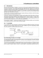
3.1 INTRODUCTION
The shoreline is a unique and complex feature and has been recognized as such by
the International Geographic Data Committee (IGDC), which designates it as one
of 27 key distinct features on the earth’s surface. A shoreline is defined as the line
of contact between land and a body of water. Although it is easy to define, the
shoreline is difficult to capture because of the natural variability of water levels.
An accepted method of capturing this line of interface is to determine the tide-
coordinated shoreline, which is the shoreline extracted from a specific tide water
level. NOAA uses Mean Lower Low Water (MLLW) and Mean High Water
(MHW) in this way to map shorelines that can be georeferenced. Both the MLLW
and MHW are calculated from averages over a period of 18.6 lunar years.
Like the shoreline, shoreline mapping techniques are changing and being
improved upon. At present, photogrammetric techniques are employed to map the
tide-coordinated shoreline from aerial photographs that are taken when the water
level reaches the desired level. Aerial photographs taken at these water levels are
more expensive to obtain than remote sensing (RS) imagery. With the
development of remote sensing technology, satellites can capture high-resolution
imagery with the capability of producing stereo imagery: one such source is the
IKONOS satellite images. The question is: is it possible to use RS imagery to map
the shoreline so that we can reduce the costs and improve mapping efficiency and
accuracy?
During our study we extracted shorelines from aerial photos, simulated and
actual IKONOS imagery, and the intersection between a Coastal Terrain Model
(CTM) and the water level. We estimated the accuracies of these shorelines and
analyzed the potential of these techniques for practical shoreline mapping by
comparing the extracted dataset with the shorelines from the United States
Geological Survey (USGS) topological maps and National Oceanic and
Atmospheric Administration (NOAA) nautical charts.
© 2005 by CRC Press LLC
3.2 SHORELINE EXTRACTION
To evaluate the new shoreline mapping techniques it is necessary to compare the
results with a current shoreline product. In our study, the shoreline extracted from
the tide-coordinated aerial photos was used as the reference shoreline and the other
shorelines were compared with it to assess their relative accuracies. Shorelines
from USGS Digital Line Graphs (DLG) and a NOAA Nautical Chart were
digitized to facilitate the evaluation of the new results. The extraction methods
used are discussed in the following sections.
3.2.1 Shoreline from aerial photos
A shoreline was digitized from tide-coordinated aerial orthophotos. This product
was chosen as the baseline in our analysis due to its high accuracy. The aerial
photos were commissioned by NOAA in 1997 when the water surface reached the
specified level (MLLW). The photo scale is about 1:20,000 and the pixel size is
about 0.6 meters on the ground. This shoreline is tide-coordinated to the mean
lower low water level. A Global Positioning System (GPS) survey was carried out
in 2000 to obtain control points for the bundle adjustment. Eight control points
were used in the adjustment. The Root Mean Square (RMS) numbers indicate a
good precision in this adjustment: 0.106, 0.107 and 0.073 meters in the X, Y and Z
directions, respectively. Based on the bundle adjustment results, Digital Terrain
Models (DTMs) and orthophotos were generated in sequence. Then, the
orthophoto mosaic was created with a resolution of 1 meter. The shoreline was
digitized manually from this orthophoto mosaic. The task was accomplished using
ERDAS software.
3.2.2 Shorelines from simulated and actual IKONOS images
IKONOS imagery has two resolutions, 1-meter panchromatic and 4-meter
multispectral. We first obtained 4-meter multispectral geo-referenced imagery for
our project. The stereo 1-meter images were still pending when we produced the
shorelines in this paper. To study the potential of 1-meter stereo imagery in
shoreline mapping, we simulated the imaging procedure and obtained the
simulated IKONOS 1-meter stereo imagery using rational functions (RFs). The
shoreline extracted from aerial orthophotos was used for back-projecting to the
simulated IKONOS raw backward- and forward-looking images. The resulting
shorelines on IKONOS raw images show that RFs work very well. This indicates
that we can use RFs to extract high accuracy 3-D shorelines from real IKONOS 1-
meter imagery provided that we can find well-matched conjugate points on raw
IKONOS images along the shorelines. To improve the accuracy of 4-meter
IKONOS real data, 8 control points were used to perform planar polynomial geo-
correction. The RMS in the X and Y directions are 1.048 meters and 1.1028 meters
respectively. A shoreline was extracted from the refined IKONOS image.
© 2005 by CRC Press LLC
3.2.3 Shoreline from the intersection between a CTM and the water level
This idea comes from the definition of a shoreline as the contact or intersection
line between the water level and the land. We tried to obtain the land model and
water surface model (WSM) and then compute the intersection line of these two
models. This method is intuitive to people’s perception of shoreline (See the
profile in Figure 3.1 and the colour insert following page 164). The CTM depicts
the elevation and bathymetry in the coastal area. The water surface model is
obtained from the Great Lakes Forecasting System at The Ohio State University
(OSU). To extract the shoreline, these two models were overlaid and the WSM
was subtracted from the CTM to get an output layer. Theoretically, the shoreline
should be the line with the zero value in the output layer. In practice, the zero
pixels do not form a line due to random errors in these two data models introduced
from data acquisition and sampling. We chose a small value range for the study
and obtained a shoreline strip. We then took one side edge of the strip as the
shoreline for our study. We employed this method because the strip is very thin
and it is very small compared to the error of the CTM.
3.2.4 Shorelines from other sources
Besides the above shorelines, four other shorelines were used for the analysis in
our study. Among them, two digital shorelines were provided by the Ohio
Department of Natural Resources (ODNR), the third one was extracted from a
USGS DLG and the fourth one was digitized from a NOAA Nautical Chart.
Figure 3.1 Generation of Digital Shorelines
© 2005 by CRC Press LLC
3.3 ESTIMATION OF THE ACCURACY OF THE SHORELINES
The accuracy of these shorelines was analyzed in our study by considering the data
sources and the extraction methods. More extensive work will be done in the
future to further investigate this important issue.
From the bundle adjustment and conjugate point matching, the DTM
standard deviation derived from the aerial photographs is estimated to be 2.1m in
X and Y coordinates. Considering the error introduced by resampling from the
aerial photos of a 0.6m resolution, the 1-meter orthophoto has an estimated
standard deviation of about 2.1m. The identification error of the shoreline from the
orthophoto may introduce 1.5 pixels, that is 1.5m, considering those situations
where the water and land separation is very hard to define. Therefore, the shoreline
from the aerial orthophoto has an estimated standard deviation of about 2.6m if we
apply a simple model of error propagation.
The accuracy of the shoreline derived from 1-meter simulated IKONOS
imagery should be about 2-4m (Zhou and Li, 2000), considering the fact that the
accuracy of 3D ground points reaches 2-3m with GCPs and the accuracy of
identifying and locating conjugate shoreline points is about 1.5 pixels (1-2m). The
4-meter IKONOS images have an accuracy of 23.6m
( After polynomial
georectification using 8 GPS control points, the difference between the GPS and
computed coordinates at the control points is about 6m. An optimistic estimation
of the shoreline accuracy derived from the 4-meter IKONOS images in this
specific case is about 8.5m.
The accuracy of the shoreline derived from a CTM and the water level is
affected by the accuracy of the CTM and the accuracy of the water level. The
CTM comes from the DTM generated in turn from the aerial photos and the
bathymetry. The DTM has an accuracy of 2.1m and the bathymetry has an
estimated accuracy of 40m. When we merged these two data sets, we select the
DTM grid points in the overlapping area. If there is gap between the two data sets,
we interpolate the elevations using weights of 2/3 from DTM and 1/3 from
bathymetry where the standard deviation of the CTM is about 13.4m. Overall the
accuracy of the CTM is from 2.1m to 13.4m for the area where the water surface
model intersects with the CTM. The water level data is accurate to several
centimeters. Taking 5 degrees to be the coastal slope in worse cases and 5cm the
water level error, we can estimate the horizontal accuracy of the intersected
shoreline caused by the water level error to be about 0.6m. Therefore, the final
accuracy of the digital shoreline is about 13.4m with the CTM contributing the
greatest source of error.
The NOAA T-sheets have large and medium scales: from 1:5,000 to
1:40,000. Taking 0.5 mm on the map as error source, the accuracy of the digitized
shoreline from the T-sheet is about 2.5m to 20m. The shoreline digitized from the
USGS DLG (1:24,000) should have an accuracy of within 12m. The ODNR map
scale is 1:12,000. Again, using 0.5mm as the shoreline digitizing error, the
estimated error of the shoreline is about 6m.
© 2005 by CRC Press LLC
Table 3.1 Estimated accuracy of the shorelines derived from various sources
Shoreline Estimated standard deviation
T-sheet 2.5m to 20m depending on scale
USGS DLG 12m (1:24,000)
ODNR map 6m (1:12,000)
Orthophoto 2.6 meters
CTM and water level 2m-13m dep. on CTM quality
IKONOS 1-meter simulated image 2-4 meters
IKONOS 4-meter image 8.5 meters
3.4 DIFFERENCE AND SHORELINE CHANGE ANALYSIS
The shorelines were acquired at different times and differences can be seen in the
results (Plate 3.1). There are two possible interpretations of the shoreline
differences. One is that the shoreline indeed changed in the real world. The other
possibility is that the differences were introduced as shoreline mapping errors.
From our analysis of the accuracies above, the shoreline from the aerial
orthophotos has the highest accuracy, and so we used it as the baseline for the
difference analysis. The analysis was performed in raster format because of the
efficiency of this method. The first task was to convert the vector shorelines into
raster shorelines. The resulting pixel size was 2.5 meters. The procedure is
outlined in Figure 3.2.
Figure 3.2 Difference Analysis Procedure
This analysis involved comparing every point on the test shorelines with the
reference shoreline, which was derived from the aerial orthophoto, in a
perpendicular direction toward the reference shoreline. In the buffer zone of the
reference shoreline we created pixels whose value represented the distance of each
© 2005 by CRC Press LLC
pixel to the reference shoreline. By overlaying other raster shorelines with the
buffer image we were able to discern and quantify differences between the
shorelines and the reference shoreline. For example, for the shoreline from the
simulated IKONOS images, each point on the shoreline has a value of the shortest
distance to the reference shoreline. Finally, we calculated some statistic indicators
including RMS of the differences for the shorelines derived from the 4-m
IKONOS images and the digital models (table 3.2).
Table 3.2 Statistics of the differences between derived shorelines and the reference shoreline
Points
used
Avg.
Dif.
(pixel)
Avg.
Dif.
(m)
Max.
Dif.
(pixel)
Max.
Dif.
(m)
RMS
(pixel)
RMS
(m)
Shoreline
from 4-m
IKONOS
images
6652 4.02 10.04 16 40.0 4.91 12.27
Digital
shoreline
4590 2.34 5.84 9 22.5 2.74 6.84
The accuracies of the shorelines derived from the 4-meter IKONOS images
and the aerial orthophoto are 8.5m and 2.6m respectively; as a result, the estimated
accuracy of the difference between them should be 8.9m, which is smaller than the
RMS value 12.27m in table 3.2. This may indicate the actual shoreline change
during the period from July 1997 when the aerial photos for the reference
shoreline were taken to October 2000 when the 4-meter IKONOS images were
taken. In addition, the IKONOS shoreline is an instantaneous shoreline, instead of
a tide-coordinated shoreline. The water level in October was 0.2-0.3 meters lower
than in July creating artificial shoreline accretion. We are developing methods that
correct instantaneous shorelines to tide-coordinated shorelines and then compare
them. For the digital shoreline from the CTM and WSM intersection, the RMS
value 6.842m in table 3.2 is smaller than the worse case shoreline error of 13m in
table 3.1. The difference can be introduced by two different factors. One is the
seasonal water level difference, which can introduce a large difference in a flat
area like Sheldon Marsh. Another factor is the difference between the accuracies
of DTM and bathymetry in CTM. If the DTM covers the coastal surface up to the
MLLW or better (this is the case in our research), the water surface model
intersects with the DTM portion of the CTM and results in smaller errors;
otherwise, the shoreline would be intersected by the water surface model, and the
bathymetric part or the interpolated part of the CTM produces large errors.
Observing the differences between the reference shoreline and earlier
shorelines from the maps, they may represent the shoreline changes (erosion) that
occurred in long time periods. The earliest shoreline in our study is the shoreline
from 1973 ODNR map, 24 years before the aerial photos for the reference
shoreline were taken in 1997.
© 2005 by CRC Press LLC
3.5 CONCLUSIONS
From the analysis above, we can draw several conclusions. First, we determined
that the method for generation of digital shorelines from CTM and WSM can be
used in mapping instantaneous shorelines. The generated shorelines can meet the
accuracy requirement for certain user communities. Additionally, this work shows
that high-resolution satellite imagery, such as IKONOS imagery, has the potential
to become a tool in shoreline mapping and coastal change detection, and that it
may reduce mapping costs. Finally, our study confirms that to detect coastal
changes, tide-coordinated shorelines must be derived from the instantaneous
shorelines so that the amount of shoreline change can be estimated objectively.
3.6 ACKNOWLEDGEMENTS
The research was supported by a Sea Grant – NOAA Partnership program with the
collaboration of CSC, NGS and OCS of NOAA. Special thanks go to Dr. Keith
Bedford and Dr. Philips Chu for providing the water level data. We appreciate the
assistance and co-operation of Dr. David Schwab of the GLERL of NOAA during
Ruijing Ma’s PEGS Professional Development Project in Ann Arbor, MI. We also
appreciate the continuous support and help from Dr. Scudder Mackey of the Lake
Erie Geology Group of the ODNR in Sandusky, OH.
3.7 REFERENCES
Cheng, P. and Toutin, T., 2000, Orthorectification of IKONOS Data Using
Rational Function. In Proceeding of ASPRS Annual Convention, Washington
D.C.
Dowman, I., and Dolloff, J.T., 2000, An Evaluation of Rational Functions for
Photogrammetric Restitution. International Archives of Photogrammetry and
Remote Sensing, 33(B3), pp. 254–266.
Horstmann, O. and Molkenthin, F., 1996, Advanced Grid Modeling for Coastal
and Nearshore Regions. The International Conference for Hydroinformatics,
Zurich.
Li, R., 1998, Potential of High-Resolution Satellite Imagery for National Mapping
Products. Photogrammetric Engineering and Remote Sensing, 64(2), pp. 1165–
1169.
Li, R. and Zhou, G., 1998, Coastline Mapping and Change Detection Using One-
Meter Resolution Satellite Imagery. Research proposal, Dept. of Civil
Engineering and Geodetic Science, the Ohio State University.
Li, R., Zhou, G., Gonzalez, A., Liu, J. K., Ma, F. and Felus, Y., 1998, Coastline
Mapping and Change Detection Using One-Meter Resolution Satellite Imagery.
Project Report submitted to Sea Grant/NOAA, pp. 88.
Liu, Ernie, 1998, Developing Geographic Information System Applications in
Analysis of Responses to Lake Erie Shoreline Change, MS. thesis, The Ohio
State University.
NOAA, 1997, Shoreline Mapping.
© 2005 by CRC Press LLC
Peuquet, D.J. and Duan, N., 1995, An event-based spatio-temporal data model
(ESTDM) for temporal analysis of geographical data. International Journal of
Geographical Information Systems, 9(1), pp. 7–24.
Raper, J. and Livingstone, D., 1995, Development of a Geomorphological Spatial
Model Using Object-oriented Design. International Journal of Geographical
Information Systems, 9 (4), pp. 359–384.
Schwab, D. J. and Sellers, D. L., 1980, NOAA Data Report ERL GLERL-16,
Tao, C.V. and Hu, Y., 2000, Investigation of the Rational Function Model. In
Proceeding of ASPRS Annual Convention, Washington, D.C.
Wang, Z., 1990, Principles of Photogrammetry (with Remote Sensing). (Wuhan,
China: Wuhan Technical University of Surveying and Mapping and Publishing
House of Surveying and Mapping).
Worboys, M. F., 1992, A Model for Spatio-temporal Information. In Proceedings
of the 5th International Symposium on Spatial Data Handling, pp. 602–611.
Worboys, M.F., 1994, Unifying the Spatial and Temporal Components of Spatial
Information. Advances in GIS Research In Proceedings of the 6th International
Symposium on Spatial Data Handling, Edinburgh, pp. 505–17.
Yang, X., 2000, Accuracy of Rational Function Approximation in
Photogrammetry. In Proceeding of ASPRS Annual Convention, Washington,
D.C.
Zhou, G., and Li, R., 2000, Accuracy Evaluation of Ground Points from IKONOS
High-Resolution Satellite Imagery. Photogrammetric Engineering and Remote
Sensing, 66 (9), pp. 1103–1112.
© 2005 by CRC Press LLC