Phsicochemical Treatment of Hazardous Wastes - Chapter 13 doc
Bạn đang xem bản rút gọn của tài liệu. Xem và tải ngay bản đầy đủ của tài liệu tại đây (1.16 MB, 42 trang )
13
Zero-Valent Iron
13.1 Introduction
The use of zero-valent iron to reduce chlorinated hydrocarbons was first
reported in patent literature by Sweeny and Fischer in 1972; however,
Sweeny and Fischer never published their studies in peer reviewed journals,
so their work was overlooked by the research community (Gillham and
O’Hannesin, 1994). In the late 1980s, Reynolds observed that organics dis-
appeared from the iron pipes used in his study on the corrosion of PVC and
iron pipes by water contaminated with organics. Several years later, Gillham
realized the potential of using the reduction ability of zero-valent iron for
practical purposes and holds several patents for the application of zero-
valent iron degradation of organic compounds (Wilson, 1995).
Pump-and-treat and impermeable confinement are frequently used to
degrade halogenated and nonhalogenated hydrocarbons in groundwater;
however, these remediation techniques have limitations. For example,
pump-and-treat only transfers contaminants to another media such as air
stripping or activated carbon. In addition, the discharge of large volumes of
water and the production of secondary waste may be costly. Also, the
hydraulic characteristics of the aquifer may be adversely affected. Permits
are required for discharge, and groundwater rights have to be purchased for
the disposal of large volumes of treated groundwater, which may result in
excessive operating costs (Cantrell and Kaplan, 1997). The use of a common
alternative, biological degradation, has increased for remediation, but gain-
ing an understanding of the biochemical pathways and associated by-prod-
ucts involved, as well as developing effective strains of bacteria and
managing the population of bacteria, can be difficult and the process has not
yet been well defined (Gillham and O’Hannesin, 1994).
Zero-valent iron is a promising
in situ
remediation technology for the
degradation of many common pollutants, as it is comparatively inexpensive,
does not restrict land use, and requires no energy for operating. Zero-valent
iron has been successfully utilized to destroy trichloroethenes, chromate,
chlorinated organics, and mixed wastes. It is capable of reducing and
TX69272_C13.fm Page 491 Tuesday, November 11, 2003 12:32 PM
© 2004 by CRC Press LLC
492
Physicochemical Treatment of Hazardous Wastes
dehalogenating a wide variety of halogenated hydrocarbons over wide con-
centration ranges (Hardy and Gillham, 1996). In addition, iron is nontoxic
and inexpensive (Gillham and O’Hannesin, 1994). It is easily oxidized by
organic compounds, thereby reducing the contaminant without an addi-
tional reactant. In addition to being highly reductive to many halogenated
hydrocarbons, zero-valent iron can reduce highly mobile oxycations (UO
2
2+
)
and oxyanions (CrO
4
2–
, MoO
4
2–
, TcO
4
–
) into insoluble forms (Cantrell and
Kaplan, 1997).
This chapter presents the theory and application of zero-valent iron and
includes the relevant
in situ
chemical/physical processes. To illustrate these
in situ
technologies, the basic mechanisms of adsorption reduction and oxi-
dation processes are discussed for
in situ
treatment of (1) organic pollutants,
(2) heavy metals, and (3) mixtures of organic and inorganic pollutants. The
history of zero-valent iron, current applications, mechanisms and kinetics of
the system, system improvements, and advantages and disadvantages for
zero-valent iron are also discussed.
13.2 Fundamental Theory
The reactions in zero-valent iron are heterogeneous due to the strong depen-
dence of the reaction rate on the surface area of the iron (Burris et al., 1995).
The surface reaction proceeds in four steps. First, the reactant undergoes
mass transport from the groundwater to the iron surface (Matheson and
Tratnyek, 1994). Second, the contaminant is absorbed onto the surface of the
iron, where the chemical reaction occurs. Third, the reaction products desorb
from the surface, which allows the site to become available for another
reaction (Burris et al., 1996a). Finally, the products of the reaction return to
the groundwater. Rate limitation could occur at any step. Where it may not
be the sole limitation, mass transport plays an essential role in the kinetics
of dechlorination (Matheson and Tratnyek, 1994).
Essentially, reduction of hazardous wastes by zero-valent iron is due to
the beneficial corrosion of iron. This process takes advantage of the chemical
reaction that occurs when iron is oxidized. The contaminant is the oxidant
(Fairweather, 1996), while zero-valent iron is a strong reductant capable of
dehalogenating several halogenated hydrocarbons (Kaplan et al., 1996).
Commercial-grade iron and industrial scrap iron are sufficient to reduce
chlorinated solvents (Matheson and Tratnyek, 1994). Although iron is actu-
ally consumed during the reaction, it remains effective for a long period of
time. For example, 1 kg of iron can dechlorinate chloromethane at a concen-
tration of 1 mg/L and sufficiently treat 0.5 million liters of water (Gillham
and O’Hannesin, 1994).
The reductive reaction is slow under anaerobic conditions, because iron
may be oxidized by oxygen. Chlorinated contaminants possess an oxidizing
TX69272_C13.fm Page 492 Tuesday, November 11, 2003 12:32 PM
© 2004 by CRC Press LLC
Zero-Valent Iron
493
potential similar to that for oxygen (Tratnyek, 1996). When strong oxidizing
compounds such as chlorinated contaminants are not present, the iron is
spontaneously corroded in water (Matheson and Tratnyek, 1994).
13.2.1 Thermodynamics
The reaction during reduction of organic pollutants by Fe
0
has two parts.
The anodic half-reaction produces Fe
2+
from Fe
0
and causes the iron metal
to corrode (Agrawal and Tratnyek, 1996):
Fe
0
+ 2H
+
Fe
2+
+ H
2
(13.1)
The cathodic half-reaction varies with the reactivity of the available electron
acceptors, such as H
+
and H
2
O in aqueous solutions. If conditions are aerobic,
the cathodic half reaction makes O
2
, which is the electron acceptor, and H
2
will not be produced (Agrawal and Tratnyek, 1996):
Fe
0
+ 2H
2
O Fe
2+
+ H
2
+ 2OH
–
(anaerobic corrosion) (13.2)
Fe
0
+ 2H
2
O + O
2
2Fe
2+
+ 4OH
–
(aerobic conditions) (13.3)
The redox pair formed from oxidizing the zero-valent iron has a reduction
potential of –0.440 V; therefore, zero-valent iron can reduce hydrogen ions,
carbonate, sulfate, nitrate, and oxygen, in addition to alkyl halides (Matheson
and Tratnyek, 1994). Both Equation (13.2) and Equation (13.3) cause the pH
to increase.
Zero-valent iron and organic substrate can react with a net result of iron
oxidation and reduction of the substrate. In such a reaction, iron acts as a
reducing agent:
Fe
0
Æ
Fe
2+
+ 2e
–
(13.4)
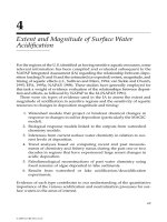
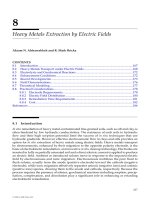
The Pourbaix diagram shown in Figure 13.1 illustrates the thermodynamic
stability of iron species in aqueous solutions of a few organic substrates. The
relative position of each substrate shows that the reaction between iron and
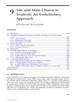
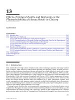
the corresponding organic is thermodynamically favorable. Three elemen-
tary reactions involved in the reductive dechlorination of organic com-
pounds are shown in Figure 13.2.
13.2.2 Kinetics
While the reaction thermodynamics is important, the reaction kinetics is
equally important in designing zero-valent iron system; furthermore, the
¨Ææ
¨Ææ
¨Ææ
TX69272_C13.fm Page 493 Tuesday, November 11, 2003 12:32 PM
© 2004 by CRC Press LLC
494
Physicochemical Treatment of Hazardous Wastes
reaction is a heterogeneous reaction. The kinetics of heterogeneous reactions
involving Fe
0
is determined by the following factors:
• The reaction rate constants from Equation (13.1) to Equation (13.3)
• Physical processes on the surface of the catalyst (reducing agent),
including its properties
• Mass transfer limitations and diffusion effects
• Sorption/desorption processes involving the substrate and avail-
ability of active reaction sites on the iron surface
• Fluid flow characteristics, including velocity, flow regime
The mass transfer limitations have been shown to be less significant in
regard to the kinetics of chlorinated aliphatics based on relatively slow rates
of degradation (Scherer et al., 2000). On the other hand, nitroaromatics and
azo dyes have higher reduction rates under which the diffusion and mass
transfer effects may become reaction rate-limiting factors (Agrawal and Trat-
nyek, 1996). Scherer et al. (2000) identified three steps that may impose
limitations on the reduction rates. The formation of precursor complex on
active metal sites can be rate limited by the number of reaction sites. Burris
et al. (1996) suggested that the hydrophobicity of the contaminant may
significantly affect the sorption rate of substrates. Scherer et al. (2000) illus-
FIGURE 13.1
Eh–pH diagram (or Pourbaix diagram) showing equilibria with water, iron, and common
environmental contaminants including perchloroethene (PCE), nitrobenzene (ArNO
2
), and
chromate (Cr[VI]). Hematite (
a
-Fe
2
O
3
) and magnetite (Fe
3
O
4
) are assumed to be the controlling
phases for iron speciation. The stability lines for the reduction of nitrobenzene (ArNO
2
) to
(ArNH
2
), Cr(VI) to Cr(III), and PCE to TCE are superimposed to show the instability of Fe
0
in
the presence of these contaminants. (From Scherer, M.M. et al.,
CRC Crit. Rev. Environ. Sci.
Technol.
, 30(3), 363–411, 2000. With permission.)
Pe
17
11
5
-1
-7
-1 4
Eh (V versus SHE)
1.0
0.5
1.
0
0.0
-0.5
0 2 4 6 8 1 0 12 14
Fe
0
Fe
3
O
4
(s)
H
2
H
2
O
Fe
2+
Fe
3+
Cr(VI)
Cr(III)
PCE
TCE
O
2
H
2
O
ArNO
2
ArNH
2
Fe
2
O
3
(s)
TX69272_C13.fm Page 494 Tuesday, November 11, 2003 12:32 PM
© 2004 by CRC Press LLC
Zero-Valent Iron
495
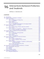
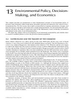
trated that the transfer of electrons from the surface of the reducing agent
to the substrate could affect the rates by the three major mechanisms shown
in Figure 13.3:
• Electron transfer from bare iron metal exposed by pitting of the oxide
layer, while the pitting mechanism involves localized corrosion and
possible catalytic dissolution pathways
• Electron transfer from conduction bands in the oxide layer
• Electron transfer from adsorbed or lattice Fe(II) surface area, express-
ing reduction of a sorbed or lattice surface site
FIGURE 13.2
Scheme showing proposed pathways for reductive dehalogenation in Fe
0
–H
2
O systems: (A)
direct electron transfer from iron metal at the metal surface; (B) reduction by Fe
2+
, which results
from corrosion of metal; (C) catalyzed hydrogenolysis by the H
2
that is formed by reduction
of H
2
O during anaerobic corrosion. Stoichiometries are shown. (From Matheson, L.J. and Trat-
nyek, P.G.,
Environ. Sci. Technol.
, 28, 2045–2053, 1994. With permission.)
Fe
3+
RCl + H
+
RH + CL
-
TX69272_C13.fm Page 495 Tuesday, November 11, 2003 12:32 PM
© 2004 by CRC Press LLC
496
Physicochemical Treatment of Hazardous Wastes
The physical properties of the iron metal are, therefore, important factors
associated with mass transfer limitations of the electron transfer processes
and reaction-limiting steps.
13.2.3 Adsorption
As a contaminant moves through soil and groundwater, chemical processes
will affect both contaminant concentration and overall hydrogeochemistry
(Schoonen, 1998) of the system. Different adsorption mechanisms cause pol-
lutants to adsorb onto the soil, volatilize, precipitate, and be part of the
oxidation–reduction processes. Adsorption is loosely described as a process
in which chemicals partition from a solution phase into or onto the surfaces
of solid-phase materials. Adsorption at particle surfaces tends to retard con-
taminant movement in soil and groundwater.
FIGURE 13.3
Conceptual models of electron transfer (ET) mechanisms at Fe
0
–oxide–water interface: (A) ET
from bare iron metal exposed by pitting of the oxide layer; (B) ET from conduction bands in
the oxide layer; (C) ET from adsorbed or lattice Fe(II) surface sites. (From Scherer, M.M. et al.,
CRC Crit. Rev. Environ. Sci. Technol.
, 30(3), 363–411, 2000. With permission.)
TX69272_C13.fm Page 496 Tuesday, November 11, 2003 12:32 PM
© 2004 by CRC Press LLC
Zero-Valent Iron
497
The three types of adsorption are (1) physical, (2) chemical, and (3)
exchange adsorption. Especially important to the success of
in situ
treatment
by Fe
0
are the soil characteristics, which affect soil sorptive behavior such as
mineralogy, permeability, porosity texture, surface qualities, and pH. Phys-
ical adsorption is due to van der Waal’s forces between molecules where the
adsorbed molecule is not fixed on the solid surface but is free to move over
the surface and may condense and form several superimposed layers. An
important characteristic of physical adsorption is its reversibility. On the
other hand, chemical adsorption is a result of much stronger forces with a
layer forming, usually of one molecule thickness, where the molecules do
not move. It is normally not reversible and must be removed by heat. The
exchange adsorption and ion exchange process involves adsorption by elec-
trical attraction between the adsorbate and the surface (Rulkens, 1998).
Adsorption may occur in a combination of three possible mechanisms:
hydrophobic expulsion, electrostatic attraction, and complexation. Most non-
polar compounds, such as various organics, adsorb by this mechanism, and
the degree of partitioning is correlated to the octanol/water partitioning
coefficient,
K
ow
. Polar substrates such as various metals sorb via electrostatic
attraction and complexation. Table 13.1 shows the typical sorption mecha-
nisms and typical examples.
Sorption isotherm curves are graphical relationships showing the parti-
tioning between solid and liquid form where mass adsorbed per unit mass
of dry solids (
S
) is plotted against the concentration (
C
) of the constituent
in solution.
K
is the sorption equilibrium constant;
N
is a constant describing
the intensity of sorption. The linear sorption isotherm can be expressed as
follows:
S
=
K
d
C
N
(13.5)
TABLE 13.1
Sorption Mechanisms in Soils
Mechanism Other Terminology Examples
Hydrophobic expulsion Partitioning Nonpolar organics (e.g., PCBs, PAHs)
Electrostatic attraction Outer-sphere
Nonspecific
Physisorption
Physical
Ion exchange
Some anions (e.g., NO
3–
)
Alkali and alkaline earth metals (Ba
2+
,
Ca
2+
)
Complexation reaction Inner sphere
Specific
Chemisorption
Chemical
Ligand exchange
Transition metals (e.g., Cu
2+
, Pb
2+
,
CrO
4
2–
)
Source:
Adapted from Scherer, M.M. et al.,
CRC Crit. Rev. Environ. Sci. Technol.
, 30(3), 363–411,
2000.
TX69272_C13.fm Page 497 Tuesday, November 11, 2003 12:32 PM
© 2004 by CRC Press LLC
498
Physicochemical Treatment of Hazardous Wastes
The Freundlich isotherm can be described as:
S
=
K
d
C
1/
N
(13.6)
The Langmuir isotherm is used to describe single-layer adsorption based on
the concept that a solid surface possesses a finite number of sorption sites.
When these active sites are filled, the site will no longer sorb solute from the
solution:
S
=
K
a
d
•
G
max
(13.7)
where
a
= absorption constant related to the binding energy (L/mg), and
G
max
= maximum amount that can be adsorbed by the solid (mg/kg).
Because adsorption isotherms are equilibrium equations, the rate at which
the material is adsorbed has to be studied in terms of chemical affinities,
pH, solubility, hydrophobicity, and many other physical and chemical char-
acteristics.
Because organic nonpolar compounds have stronger attraction to organic
matter than to mineral content, the amount of adsorption of an organic
contaminant is more dependent on the organic content of the soil. The
adsorption partition coefficient is generally used to determine this adsorp-
tion amount, as it is empirically related to the organic fraction of the soil
(
f
oc
), and the normalized partition coefficient
K
oc
can be expressed as follows:
K
p
=
K
oc
f
oc
(13.8)
The amount of adsorption is also dependent on the moisture content of the
soil, as water competes for adsorption sites, as illustrated in Figure 13.4.
In a zero-valent iron system, pollutants will be retained at the Fe surface.
Movement of metals into other environmental compartments (i.e., ground-
water, surface water, or the atmosphere) should be minimal as long as the
retention capacity of Fe is not exceeded. The extent of movement of a
pollutant in the zero-valent iron system is intimately related to the solution
pH, the surface chemistry of the Fe, the specific properties of pollutants,
and the associated waste matrix. The retention mechanisms for pollutants
include adsorption of the pollutant by the Fe surfaces and precipitation.
The retention of cationic metals by Fe has been correlated with Fe proper-
ties such as pH, redox potential, surface area, cation exchange capacity,
organic matter content, clay content, iron and manganese oxide content,
and carbonate content. Anion retention has also been correlated with pH,
iron and manganese oxide content, and redox potential. In addition to Fe
properties, consideration must be given to the type of pollutants, their
concentration, the competing ions, and the complexing ligands. Transport
of metals associated with various wastes may be enhanced due to the
following reasons (Puls et al., 1995):
TX69272_C13.fm Page 498 Tuesday, November 11, 2003 12:32 PM
© 2004 by CRC Press LLC
Zero-Valent Iron
499
• Transportation caused by metal association with mobile colloidal
size particles
• Formation of metal organic and inorganic complexes that do not
sorb to soil solid surfaces
• Competition with other constituents of waste, both organic and inor-
ganic, for sorption sites
• Deceased availability of surface sites caused by the presence of a
complex waste matrix
The available surface area of the iron has the greatest effect on the reaction
rate (Johnson et al., 1996). The iron is commonly treated with hydrochloric
acid prior to the experiment to accelerate dechlorination and improve repro-
ducibility. By cleaning the metal surface, the passive oxide layer is broken
off, the surface area is increased by etching and pitting, and the density of
highly reactive sites is increased (Agrawal and Tratnyek, 1996). Because of
FIGURE 13.4
Adsorption mechanism for nonpolar organic species. (Adapted from Semer, R. and Reddy, K.R.,
J. Haz. Mat.
, 57, 209–230, 1998.)
TX69272_C13.fm Page 499 Tuesday, November 11, 2003 12:32 PM
© 2004 by CRC Press LLC
500
Physicochemical Treatment of Hazardous Wastes
the wide range of waste characteristics and various ways in which metals
can be adsorbed to the Fe surface, the extent of pollutant retention by a soil
is specific to the type of site, soil, and waste involved.
13.2.4 Halogenated Hydrocarbons
Dechlorination is a surface reaction with the zero-valent iron serving as the
electron donor. When there is a proton donor, such as water, chlorinated
compounds will be dehalogenated. The reaction kinetics depends upon the
mass transfer to the surface of the iron, the available surface area, and the
condition of the surface. The reaction is pseudo first order, and direct contact
with the surface of the iron is required for degradation to take place (Gillham
and O’Hannesin, 1994). The basic equation for dechlorination by iron metal
is as follows:
Fe
0
+ RX + H
+
Fe
2+
+ RH + Cl
–
(13.9)
The reduction potentials for various alkyl halides range from +0.5 to +1.5
V; therefore, when Fe
0
serves as an electron donor, the reaction is thermo-
dynamically favorable. Because three reductants are present in the treatment
system (Fe
0
, H
2
, and Fe
2+
), three possible pathways exist. Equation (13.9)
represents the oxidation of Fe
0
by reduction of a halogenated compound. In
the second pathway, the ferrous iron behaves as a reductant, as represented
in Equation (13.10). This reaction is relatively slow because the ability to
reduce a pollutant by ferrous iron is dependent on the speciation ferrous
ions, which is determined by the ligands present in the system. The third
possible pathway, Equation (13.11), is dehalogenation by hydrogen. This
reaction does not occur easily without a catalyst. In addition, if hydrogen
levels become too high, corrosion is inhibited (Matheson and Tratnyek, 1994):
2Fe
2+
+ RX + H
+
Æ
2Fe
3+
+ RH + X
–
(13.10)
H
2
+ RX
Æ
RH + H
+
+ X
–
(13.11)
If all three pathways are not possible, then reactions will be limited. Addi-
tional limitations may occur if the reaction is aerobic because Fe
3+
could be
produced by further oxidation of Fe
2+
and cause precipitation of iron oxides
(Helland et al., 1995). The end products such as ferrous chloride and ferric
oxide are not capable of reducing chlorinated compounds (Gillham and
O’Hannesin, 1994). Burris et al. (1995) state that Fe
2+
and H
2
do not have an
effect on degradation. Hardy and Gillham (1996) have suggested the possi-
bility that degradation may be due to a catalytic reaction utilizing hydrogen
produced from the reduction of water. In developing and improving the
performance of the zero-valent iron technique in the field, detail mechanisms
are important and critical for a specific site. The dominant process is the
¨Ææ
TX69272_C13.fm Page 500 Tuesday, November 11, 2003 12:32 PM
© 2004 by CRC Press LLC
Zero-Valent Iron
501
oxidation of the iron metal (Matheson and Tratnyek, 1994). The reduction of
the halogenated hydrocarbon involves the transfer of an electron and occurs
at the iron surface. A carbon-centered radical, R
∑
, is formed as:
RX +e
–
Æ
R
•
+ X
–
(13.12)
Then, a second electron transfer occurs, and the radical is protonated as in
Equation (13.13).
R
•
+ H
+
+
e
–
Æ
•
RH (13.13)
The result is dehalogenation, and during this step Fe
2+
is formed by dis-
solving into solution. Hydrocarbon formation also adds perplexity to mech-
anism determination. Because C
1
to C
5
hydrocarbons have been found in
iron and water systems, the hydrocarbons formed may be due to reduction
of aqueous CO
2
by zero-valent iron. Therefore, iron behaves as both a reac-
tant, by corroding and supplying electrons, and as a catalyst, by promoting
the formation of hydrocarbons. Ten hydrocarbons were identified up to C
5
;
also, iron pretreated with H
2
formed hydrocarbons with longer chain lengths.
The hydrocarbon concentration and the growth in chain length increase with
time; therefore, if the hydrocarbons are not desorbed, the production of the
hydrocarbons could be rate limiting in the dechlorination of chlorinated
organics. Although this does not determine the mechanism by which iron
metal removes halogens from halogenated organics, it does show that the
product distribution, carbon mass balance, and reaction rate may be affected
by catalysts (Hardy and Gillham, 1996).
For modeling purposes, zones are constructed in the column tests per-
formed. A subsurface barrier will have three zones: upgradient (area before
the barrier), iron-bearing gradient (the barrier itself), and downgradient (area
after the barrier). In the upgradient zone, the Fe
0
is oxidized to Fe
2+
and Fe
3+
by O
2
. The reaction increases the pH, and precipitation of the iron oxides is
initiated. The precipitation could reduce the permeability of the barrier and
surface area of the iron, thus reducing the reaction rate. This also causes the
iron-bearing zone and down gradient zone to be anoxic (Tratnyek, 1996).
This production of precipitates has been observed regularly in the laboratory,
but the degree to which the effect occurs in the field is under much debate.
For these reasons, buffers such as pyrite, which lowers the pH, are used.
The reactivity of the iron with the contaminants determines the feasibility
and the design of the site. Many factors contribute to the reaction rate. For
example, the oxide layer that forms on the iron affects the surface of the iron
and inhibits further corrosion, so this layer needs to be minimized. Fortu-
nately, iron possesses a “porous and incoherent” nature with oxide film, and
iron usually exhibits satisfactory degradation rates over a long period of
time (Tratnyek, 1996).
Because reaction rates vary widely among contaminants, Fe barrier
design should be dependent on the least reactive contaminant. Some
TX69272_C13.fm Page 501 Tuesday, November 11, 2003 12:32 PM
© 2004 by CRC Press LLC
502
Physicochemical Treatment of Hazardous Wastes
contaminants are quickly reduced, and others react too slowly for consid-
eration of remediation by iron. Although much data exist regarding deg-
radation rates, quantitative predictions concerning the reaction rates
cannot be made because many of the experiments are highly inconsistent
in accounting for the effect of pH, surface area of the iron, mixing rate,
and other experimental variables. Comparisons are of better quality if the
rate constants are normalized. For example, when rate constants are nor-
malized to the surface area of iron (
k
SA
), the specific rate constant varies
by only one order of magnitude for individual halocarbons. Upon further
correlation, the
k
SA
has indicated that dechlorination is more rapid for
saturated carbon than unsaturated carbons, and reaction rates are faster
for perhalogenated compounds. By obtaining this quality information, the
amount of iron required to obtain a decrease in contaminant concentration
by a magnitude of three can be calculated (Tratnyek, 1996). Also, quanti-
tative structure–activity relationships (QSARs) could be developed for such
prediction of iron required for different organic pollutants.
13.3 Degradation of Hazardous Wastes
13.3.1 Organic Pollutants
Table 13.2 presents organic classes that have been successfully degraded by
zero-valent iron.
13.3.1.1 Unsaturated Halogenated Compounds
Trichloroethylene (TCE) and perchloroethylene (PCE) require cleavage of the
carbon–halogen bonds. Two methods of cleavage are
b
-elimination by dehy-
drohalogenation, as shown in Equation (13.14), and nucleophilic substitution
by either water or hydrogenolysis in Equation (13.15). The proposed path-
ways for reduction of chloroethylenes by zero-valent iron are as follows:
RX = RX + 2e
–
Æ
R
∫
R + 2X
–
(13.14)
RX + 2e
–
+ H
+
Æ
RH + X
–
(13.15)
The reduction of the triple bond may form an olefin (Equation 13.15) or an
alkane (Equation 13.16) (Burris et al., 1995):
R
∫
R + 2e
–
+ 2H
+
Æ
RH + RH (13.16)
TX69272_C13.fm Page 502 Tuesday, November 11, 2003 12:32 PM
© 2004 by CRC Press LLC
Zero-Valent Iron
503
R
∫
R + 4e
–
+ 4H
+
Æ
RH
2
–RH
2
(13.17)
The overall reaction as shown in Equation (13.17) for the degradation of the
TCE produces ethene and ethane at a ratio of 2:1:
C
2
HCl
3
+ 3H
+
+ 6e
–
Æ
C
2
H
4
+ 3Cl
–
(13.18)
Ethene and ethane account for 80% of the mass of the hydrocarbons
identified as products. Trace amounts of methane and acetylene are also
produced (Orth and Gillham, 1996). The reduction of PCE forms
cis
-1,2-
dichloroethylene (DCE),
trans
-1,2-DCE, 1,1-DCE, vinyl chloride, ethylene,
dichloroacetylene, acetylene, ethene, ethane, chloroacetylene, methane,
and several alkenes ranging from C
3
to C
6
. The trace amounts of dichloro-
ethylene and vinyl chloride formed during the reduction of PCE and TCE
are further reduced (Burris et al., 1995). Reaction rates vary with substrate,
chemical, and microbiological conditions. Selected
t
1/2
values are provided
in Table 13.3.
TABLE 13.2
Organic Contaminants Treated by Fe
0
Methanes Tetrachloromethane
Trichloromethane
Dichloromethane
Ethanes Hexachloroethane
1,1,1-Trichloroethane
1,1,2-Trichloroethane
1,1-Dichloroethane
Ethenes Tetrachloroethene
Trichloroethene
cis-1,2-Dichloroethene
trans-1,2-Dichloroethene
1,1-Dichloroethene
Vinyl chloride
Propanes 1,2,3-Trichloropropane
1,2-Dichloropropane
Aromatics Benzene
Toluene
Ethylbenzene
Other Hexachlorobutadiene
1,2-Dibromoethane
Freon 113
N-nitrosodimethylamine
Source: USEPA, EPA/600/R-98/125, U.S.
Environmental Protection Agency, Washington,
D.C., 1998.
TX69272_C13.fm Page 503 Tuesday, November 11, 2003 12:32 PM
© 2004 by CRC Press LLC
504 Physicochemical Treatment of Hazardous Wastes
13.3.1.2 Saturated Halogenated Compounds
Helland et al. (1995) compared the degradation rates of halogenated aliphatic
compounds by zero-valent iron in both anoxic and oxic reductions. The
reactions are as follows:
2Fe
0
Æ 2Fe
2+
+ 4e
–
(13.19)
3H
2
O Æ 3H
+
+ 3OH
–
(13.20)
2H
+
+ 2e
–
Æ H
2
(13.21)
2Fe
0
+ 3H
2
O + X-Cl Æ 2Fe
2+
+ 3OH
–
+ H
2
+ X-H + Cl
–
(13.22)
When water dissociation is taken into consideration, the reaction becomes
(Gillham and O’Hannesin, 1994):
Fe
0
+ H
2
O + X–Cl Æ Fe
2+
+ OH
–
+ X–H + Cl
–
(13.23)
If no dissociation of water occurs, the following reaction will take place:
X–Cl + H
+
+ 2e
–
Æ X–H + Cl
–
(13.24)
The reaction proceeds until each chlorine ion is removed. For example,
carbon tetrachloride would be reduced to chloroform, then to methylene
chloride, and finally to methane (the reduction of methylene chloride takes
several months, however). No degradation products other than the parent
compounds were found; therefore, degradation is simple, reductive dechlo-
rination, with the zero-valent iron serving as an electron donor. The reaction
was pseudo first-order and the reaction constant, k, decreased with each
additional dehalogenation step (Gillham and O’Hannesin, 1994).
TABLE 13.3
t
1/2
Values for Selected Halogenated Aliphatics
Compound t
1/2
(min)
Perchloroethylene 17.9
Tetrachloroethene —
Trichloroethene 13.6
1,1-Dichloroethene 40.0
trans-1,2-Dichloroethene 55.0
cis-1,2-Dichloroethene 432.0
Vinyl chloride 374.0
Source: Gillham, R.W. and O’Hannesin, S.F., Ground
Water, 32(6), 958–967, 1994. With permission.
TX69272_C13.fm Page 504 Tuesday, November 11, 2003 12:32 PM
© 2004 by CRC Press LLC
Zero-Valent Iron 505
Gillham and O’Hannesin (1994) reported that the degradation rates
increased as the surface area of the iron increased with respect to the volume
of the solution. Also, degradation declined with decreasing degree of chlo-
rination. Dichloroethene is the only compound in Table 13.4 not degraded
by the zero-valent iron process.
Saturated hydrocarbons such as 1,2-dibromo-3-chloropropane (DBCP)
have been used as soil nematicides. DBCP has contaminated the ground-
water due to its extensive use. Although banned in 1977, concentrations
in some parts of the United States exceed the maximum contaminant
level of 0.2 mg/L. The dehalogenation of DBCP has two possible path-
ways: (1) a series of three hydrodehalogenation reactions requiring a
proton and two electrons for each reaction or (2) the formation of a
transitional state of propene followed by hydrogenation of the double
bond, with the product being propane in both mechanisms. The only
intermediate formed is propene, with a reaction rate constant of 0.28 ±
0.03 min
–1
(Siantar et al., 1996). Table 13.5 shows the effect of pH on the
pseudo first-order rate constants and half-lives of DBCP with or without
mixing. Table 13.6 indicates that sulfate and nitrite ions do not signifi-
cantly affect the pseudo first-order rate constants and half-lives of DBCP.
13.3.1.3 Polychlorobiphenyls
Degradation of polychlorobiphenyls (PCBs) by zero-valent iron requires tem-
peratures of 400°C (Grittini et al., 1995). At 400°C, PCBs are reduced to
biphenyls. For further degradation of the biphenyl compound, temperatures
have to exceed 500°C (Chuang et al., 1995). Under normal temperatures,
zero-valent iron has little effect on PCBs.
TABLE 13.4
t
1/2
Values for Sample Halogenated Aliphatics
Compound t
1/2
(hr)
Tetrachloromethane 0.25
Trichloromethane 33.0
Tribromomethane 0.24
Dichloromethane No decline
Hexachloroethane 0.13
1,1,2,2-Tetrachloroethane 19.2
1,1,1,2-Tetrachloroethane 4.4
1,1,1-Trichloroethane 5.3
Source: Gillham, R.W. and O’Hannesin, S.F., Ground
Water, 32(6), 958–967, 1994. With permission.
TX69272_C13.fm Page 505 Tuesday, November 11, 2003 12:32 PM
© 2004 by CRC Press LLC
506 Physicochemical Treatment of Hazardous Wastes
13.3.1.4 Nitroaromatic Compounds
Nitroaromatic compounds (NACs) are one of the widespread contaminants
in the environments. Sources of NACs are numerous; they originate from
insecticides, herbicides, explosives, pharmaceuticals, feedstock, and chemi-
cals for dyes (Agrawal and Tratnyek, 1996). Under anaerobic conditions, the
dominant action is nitro reduction by zero-valent iron to the amine. Other
pathways do exist, such as the formation of azo and azoxy compounds,
which is followed by the reduction of azo compounds to form amines. Also,
in addition to the possibility of azo and azoxy compounds, phenylhydrox-
ylamine may be an additional intermediate (Agrawal and Tratnyek, 1996).
Nitrobenzene reduction forms the amine aniline. Known for its corrosion
inhibition properties, aniline cannot be further reduced by iron. Additionally,
it interferes with the mass transport of the contaminant to the surface of the
iron. The overall reaction is as follows:
ArNO
2
+ 3Fe
0
+ 6H
+
Æ ArNH
2
+ 3Fe
2+
+ 2H
2
O (13.25)
TABLE 13.5
Effect of Ions on Pseudo First-Order Rate Constants and Half-Lives of DBCP
Transformation Using 0.1-M HEPES Buffer Solution at pH 7, Mixing at 400 rpm,
and 22°C
Aqueous Phase pH
k (hr
–1
)
(No
Shaking)
k (hr
–1
)
(Mild
Shaking)
t
1/2
(hr)
(No
Shaking)
t
1/2
(hr)
(Mild
Shaking)
Milli Q
TM
water 7 0.099 0.132 6.99 5.23
0.1-M MES 6 0.341 0.482 2.03 1.44
0.1-M HEPES 7 0.393 0.513 1.76 1.35
0.1-M Tricine 8 0.259 — 2.67 —
0.1-M CHES 9 ————
Source: Siantar, D.P. et al., Water Res., 30(10), 2315–2322, 1996. With permission.
TABLE 13.6
Effect of Sulfate and Nitrite Ions on Pseudo First-Order Rate Constants and
Half-Lives of DBCP Transformation
Concentration k (min
–1
) t
1/2
(min)
No sulfate or nitrite added 0.300 2.31
Sulfate concentration (mg/L)
3.7 0.273 2.54
19.8 0.266 2.61
27.6 0.270 2.57
Nitrite concentration (mg/L)
4.3 0.255 2.72
Source: Siantar, D.P. et al., Water Res., 30(10), 2315–2322, 1996. With permission.
TX69272_C13.fm Page 506 Tuesday, November 11, 2003 12:32 PM
© 2004 by CRC Press LLC
Zero-Valent Iron 507
The elementary steps are shown in Equation (13.26) to Equation (13.28):
ArNO
2
+ Fe
0
+ 2H
+
ArNO + 3Fe
2+
+ H
2
O (13.26)
ArNO + Fe
0
+ 2H
+
ArNHOH + Fe
2+
(13.27)
ArNHOH + Fe
0
+ 2H
+
ArNH
2
+ 3Fe
2+
+ 2H
2
O (13.28)
During the reduction of NACs, changes in corrosion and precipitation of
iron products were not significant. As long as the diffusivities of the different
substitutions on the benzene were similar, the reaction rate did not vary
significantly (Agrawal and Tratnyek, 1996). The rate constants are given in
Table 13.7.
Because nitrobenzene degradation is faster in batch experimental systems
than in column studies, a mass-transfer limitation exists; therefore, when
determining the effectiveness of in situ groundwater treatment systems,
hydraulics, mass transfer, and reaction kinetics should be taken into consid-
eration (Burris et al., 1996).
Weber (1996) performed additional experimental studies on 4-aminoa-
zobenzene (4-AAB). The compound was chosen based on the hypothesis
that azo compounds capable of reduction by zero-valent iron and an amino
group would allow for determination of surface-reaction occurrence. The
compound 4-AAB reduces and forms aniline. The reduction of 4-AAB was
performed without cleaning the iron with hydrochloric acid, which is a
standard method in most experiments. Complete loss of 4-AAB occurred in
2 hr. When the iron was washed with hydrochloric acid, the reaction occurred
so quickly that aniline formation could not be measured. An additional
experiment with bound 4-AAB was conducted to determine if the reaction
TABLE 13.7
Pseudo First-Order Rate Constant of Substrate Reduction
Substrate k (min
–1
)
Nitrobenzene 0.0339
Nitrosobenzene 0.0339
1,3-Dinitrobenzene 0.0339
4-Chloronitrobenzene 0.0336
4-Nitroanisole 0.0327
4-Nitrotoluene 0.0335
2,4,6-Trinitrotoluene 0.0330
Parathion 0.0250
Source: Agrawal, A. and Tratnyek, P.G., Environ. Sci. Technol., 30,
153–160, 1996. With permission.
k
1
æÆæ
k
2
æÆæ
k
3
æÆæ
TX69272_C13.fm Page 507 Tuesday, November 11, 2003 12:32 PM
© 2004 by CRC Press LLC
508 Physicochemical Treatment of Hazardous Wastes
occurred at the iron surface. Because no degradation of 4-AAB occurred, the
reaction appears to be surface mediated.
When NACs are reduced, aromatic amines are formed and are of signifi-
cant toxicological concern. Zero-valent iron cannot accomplish this degra-
dation; therefore, remediation has to extend beyond the reduction of the
parent NAC (Agrawal and Tratnyek, 1996). Two methods of further reduc-
tion are biodegradation and enzyme-catalyzed coupling reactions. Biodeg-
radation can degrade the NACs further to mineralization, and the reaction
is more rapid for aromatic amines than for the biodegradation of the original
NAC compound (Burris et al., 1996b); however, biodegradation of NACs
can be difficult and can produce toxic metabolites; therefore, further reduc-
tion of the NACs can also be accomplished by enzyme-catalyzed coupling
reactions, which integrates the amine into organic matter (Monsef et al.,
1997). Both methods could be combined with nitro reduction by Fe
0
to treat
NAC contamination (Agrawal and Tratnyek, 1996).
13.3.1.5 Nitrates and Nitrites
The presence of nitrates and nitrites in groundwater is of growing concern
as it poses serious health risks. The typical sources of nitrate are nitrogen
fertilizers, septic tanks, and animal wastes. Excessive nitrates present in
groundwater can be reduced by microorganisms to nitrite, which is harmful
to human health and animals, agriculture, and the environment. Nitrites and
secondary amines can react to form nitroamines, which cause serious health
effects, including cancer. Such adverse effects with increasing nitrate con-
tamination in groundwater draw attention to treatment and removal of
nitrate and nitrite contamination in groundwater. Physicochemical removal
by ion exchange resins does not destroy nitrates, frequent resin regeneration
by salt produces much brine, and biological degradation by denitrifying
microorganisms is often slow and incomplete. The process requires expen-
sive maintenance due to production of excessive biomass.
The feasibility of chemical degradation of nitrate by reducing agents has
been investigated for application in treatment of contaminated groundwater
by Horold et al. (1993a,b). The transformation of aqueous nitrate into benign
products was studied using Fe
0
in a pH-buffered anaerobic aqueous medium
from groundwater. Their results showed that 75 to 85% of the nitrate was
reduced to ammonia at room temperature within an hour in an acidic pH
of 3. The chemical denitrification by organic and inorganic reductants and
catalysts showed a 55% reduction in nitrate within 48 hr with Fe
0
powder
in an anaerobic medium at 85°C. A rapid catalytic reduction of nitrite with
hydrogen gas using Pd metal supported on alumina and of nitrate with
hydrogen gas using a Cu–Pd bimetallic catalyst supported on alumina have
been demonstrated. This technique seemed to be efficient at the temperature
and pH ranges of natural groundwater and was recommended for an ex situ
treatment of groundwater.
TX69272_C13.fm Page 508 Tuesday, November 11, 2003 12:32 PM
© 2004 by CRC Press LLC
Zero-Valent Iron 509
To gain insight into kinetics, reaction pathways, and reaction end products,
laboratory investigations were performed by Rahman and Agrawal (1997).
Sodium nitrate and sodium nitrite were selected as model pollutants. Reac-
tions were carried out at room temperature in the dark with untreated [Fe
0
]
= 69.4 g/L. In some cases, Fe
0
was treated with 10% HCl (v/v) for nearly 2
min and then washed with deionized water four to six times prior to reaction.
The nitrate and nitrite stock solution was nearly 0.16 mM, and mixing was
achieved at 40 rpm.
Experiments with sodium nitrate showed rapid reduction by Fe
0
, with
nitrite as an intermediate and ammonia as final product. Iron acts as an
electron donor and the reduction is coupled with metal corrosion (Equation
13.9). The reduction reaction in the model system was found to proceed in
two sequential steps (Equation 13.30 and Equation 13.31), and the overall
reaction was represented as follows:
Fe
0
´ Fe
2+
+ 2e
–
(13.29)
NO
3
–
+ 2H
+
+ 2e
–
Æ NO
2
–
+ H
2
O (13.30)
NO
2
–
+ 8H
+
+ 6e
–
Æ NH
4
+ 2H
2
O (13.31)
4Fe
0
+ NO
3
–
+ 10H
+
Æ 4Fe
2+
+ NH
4
+ 3H
2
O (13.32)
In investigations into nitrate reduction with Fe
0
, the concentration of
nitrate decreased through time with concurrent increase in nitrite concen-
trations. As no nitrite was injected, the appearance of nitrite and the increase
in its concentration with concurrent decreases in nitrate concentration
throughout the experiment suggested reduction of nitrate (Equation 13.30)
by zero-valent iron (Rahman et al., 1997). The transformation reaction of
nitrate to nitrite was found to be first-order in substrate concentration, and
the reaction rate constant was obtained. These reduction experiments were
performed with untreated as well as acid-treated Fe
0
turnings. Experiments
were also performed to investigate if only nitrite was reduced with Fe
0
metal
under identical conditions. Results showed that nitrite can also be reduced
by acid treated or untreated Fe
0
metal (Rahman and Agrawal 1997). The
transformation reaction (Equation 13.31), similar to nitrate reduction, was
found to be first order in substrate concentration and, unlike nitrate, no by-
products of nitrite reduction were evident in ion chromatography. This sug-
gested that either reduced products (N
2
gas) were lost in gaseous forms or
they may be present in solution as NH
4
+
cation. The [NH
4
+
] was estimated
in a batch system after several days as the final reduction product and
indicated a mass balance of nearly 80%. The hypothesized reaction (Equation
13.35) consisted of the following steps:
NO
2
–
+ 4H
+
+ 3e
–
Æ 0.5 N
2
(gas) + 2H
2
O (13.33)
TX69272_C13.fm Page 509 Tuesday, November 11, 2003 12:32 PM
© 2004 by CRC Press LLC
510 Physicochemical Treatment of Hazardous Wastes
0.5N
2
+ 4H
+
+ 3e
–
Æ NH
4
+
(13.34)
NO
2
–
+ 8H
+
+ 6e
–
Æ NH
4
+
+ 2H
2
O (13.35)
Thus, it was observed that the first-order rate constants (k
1
) for nitrate
reduction by untreated Fe
0
increase due to the pretreatment of iron metal
with HCl; however, observed increases in the rate constant for nitrite reduc-
tion have been relatively small under similar acid pretreatment conditions.
During the first 12 hr, the rate constant for nitrate reduction showed a gradual
decline, and this decline seems to have been clearly influenced by the pres-
ence of chloride. The reaction rate constants for nitrate and nitrite reduction
by untreated Fe
0
turnings are directly dependent on the concentration of Fe
0
used, ranging between 69.4 and 208.2 g/L; thus k
1
and k
2
increase linearly
with increases in the surface area of the untreated iron. Table 13.8 demon-
strates that acid-treated Fe
0
is more reactive than its untreated counterpart.
13.3.2 Reduction of Heavy Metals
Anions or oxyanions of arsenic, selenium, chromium, technetium, and anti-
mony are important groundwater contaminants and may occur under nat-
ural groundwater conditions. Indirect precipitation of inorganic cations
results from the reduction of an anion-forming species, usually sulfate. Sul-
fate reduction generates hydrogen sulfide, which combines with metals to
form relatively insoluble metal sulfide precipitates. Many heavy metals are
treatable using this approach, including Ag, Cd, Co, Cu, Fe, Ni, Pb, and Zn,
as listed in Table 13.9 (Waybrant et al., 1998). Column experiments conducted
using a range of organic substrates demonstrated the potential to remove a
TABLE 13.8
Reduction Kinetics of Nitrate and Nitrite with an Fe
0
System
Fe
0
(g/L) Treatment
Rate
Constant
Half-Life
(hr) R
2
Conditions
Nitrate reduction
69.4 Untreated 0.0168 41.3 0.99
69.4 Acid treated 0.2592 2.67 0.97
Nitrate reduction in presence of chloride
69.4 Acid treated 0.0348 19.9 0.99 [Cl
–
] = 7 mM
69.4 Acid treated 0.089 7.78 1.00 [Cl
–
] = 70 mM
Nitrite reduction
69.4 Untreated 0.0963 7.2 0.98
69.4 Acid treated 0.1864 3.72 0.99
Source: USEPA, EPA/600/R-98/125, U.S. Environmental Protection Agency, Washington,
D.C., 1998.
TX69272_C13.fm Page 510 Tuesday, November 11, 2003 12:32 PM
© 2004 by CRC Press LLC
Zero-Valent Iron 511
range of dissolved metals at groundwater velocities similar to those observed
at sites of groundwater contamination. A field-scale reactive barrier for the
treatment of acid mine drainage and removal of dissolved Ni was installed
in 1995 at the Nickel Rim mine site near Sudbury, Ontario. It was composed
of municipal compost, leaf compost, and wood chips. Monitoring of the
reactive barrier indicates continued removal of the acid-generating capacity
of the groundwater flowing through the permeable reactive barrier (PRB)
and decreases in dissolved Ni concentrations from up to 10 mg/L to <0.1
mg/L within the PRB.
The mechanism of adsorption implies attachment of the chemical to
reactive sites on mineral surfaces. These sites usually result from an excess
either positive or negative charge on the surfaces. These surface charges
can be constant (fixed) due to ion substitutions in the mineral matrix
(isomorphous substitution), variable with pH, or a mixture of both. In
addition, the adsorption can result from either inner-sphere or outer-sphere
complexation. Inner-sphere complexation is due to actual covalent and
ionic chemical bond formation. In outer-sphere complexation, adsorption
results from ion-pair bonding due to electrostatic forces; hydration water
separates the solvated ion from the surface. Many metal oxides and some
clay minerals have net surface charges that vary with pH due to the
proportion of protonated vs. deprotonated surface sites. Among these vari-
ably charged materials are the iron oxyhydroxides (rusts) that result when
zero-valent iron corrodes. These materials are very significant to adsorption
of both inorganic and organic charged solution species (ionic species). The
charges of both the surface and the solution ion control whether adsorption
TABLE 13.9
Inorganic Contaminants Treated
Trace metals Chromium
Nickel
Lead
Uranium
Technetium
Iron
Manganese
Selenium
Copper
Cobalt
Cadmium
Zinc
Anion
contaminants
Sulfate
Nitrate
Phosphate
Arsenic
Source: Waybrant, K.R. et al., Environ.
Sci. Technol., 32(13), 1972–1979, 1998.
With permission.
TX69272_C13.fm Page 511 Tuesday, November 11, 2003 12:32 PM
© 2004 by CRC Press LLC
512 Physicochemical Treatment of Hazardous Wastes
will occur or whether the surface and the ion will repulse one another. The
pH of zero-point of charge, or pH
zpc
, is the pH at which negatively and
positively charged surface sites exist in approximately equal numbers on
the mineral. Above pH
zpc
, the surface will have a net negative charge,
enhancing cation adsorption; below pH
zpc
, the surface will have a net
positive charge, enhancing anion adsorption.
13.3.2.1 Chromium
Elemental iron, iron-bearing oxyhydroxides and iron-bearing aluminosili-
cate minerals have been observed to promote the reduction and precipitation
of Cr(VI). The overall reactions for the reduction of Cr(VI) by Fe
0
and the
subsequent precipitation of Cr(III) and Fe(III) oxyhydroxides are:
CrO
4
2–
+ Fe
0
+ 8H
+
Æ Fe
3+
+ Cr
3+
+ 4H
2
O (13.36)
(1–x)Fe
3+
+ (x)Cr
3+
+ 2H
2
Æ Fe
(1–x)
Cr
x
OOH
x
+ 3H
+
(13.37)
The main physical processes leading to the above reactions that occur with
PRB treatment are sorption, dissolution, and precipitation (USEPA, 1998).
13.3.2.2 Arsenic
Manning et al. (2002) applied zero-valent iron for treatment of arsenic (III)
and (V) and investigated their reactions with two Fe
0
materials, their iron
oxide corrosion products, and several model iron oxides. Different species
of arsenate (As(V)) and arsenite (As(III)) were treated. By applying x-ray
diffraction, scanning electron microscopy/energy-dispersive spectrometry
(SEM/ED), x-ray absorption spectroscopy, and high-performance liquid
chromatography (HPLC)/hydride generation atomic absorption spectrom-
etry, a number of corrosion products of Fe
0
were identified, including lepi-
docrocite (g-FeOOH), magnetite (Fe
3
O
4
), and maghemite (g-Fe
3
O
4
). The
results indicated that Fe(II) oxidation was an intermediate step in the Fe
0
corrosion process. Under aerobic conditions, the Fe
0
corrosion reaction does
not reduce As(V) to As(III) but the As(III) has been oxidized to As(V). The
oxidation of As(III) was also caused by magnetite and hematite minerals,
indicating that the formation of certain iron oxides during Fe
0
corrosion
favors the As(V) species as a final reaction product. It was hypothesized that
water reduction with subsequent release of OH
–
to solution on the surface
of corroding Fe
0
may also promote the oxidation of As(III) to As(V). The
existence of inner-sphere bidentate As(III) and As(V) complexes has been
assumed to have significance in the iron corrosion reaction. Thus, in situ
treatment of groundwater containing As(III) and As(V) has been demon-
strated.
TX69272_C13.fm Page 512 Tuesday, November 11, 2003 12:32 PM
© 2004 by CRC Press LLC
Zero-Valent Iron 513
13.3.2.3 Uranium
Cui and Spahiu (2002) investigated the reduction of uranium(VI) on cor-
roded iron under anoxic conditions and demonstrated that U(VI) can be
treated by Fe
0
. The anoxic conditions were attained by flushing with a gas
mixture composed of 99.97% Ar and 0.03% CO
2
through the test vessel. The
test vessel contained an oxygen trap and synthetic groundwater (10 mM
NaCl and 2 mM HCO
3–
). A corrosion product of dark green formed on the
iron surface after 3 months of corrosion. The chemical was identified as
carbonate green rust — (Fe
4
Fe
2
III)–Fe–II(OH)CO
3
. The iron foil that reacted
in a solution (10 ppm U(VI), 10 mM NaCl, and 2 mM HCO
3
) for 3 months
was analyzed by SEM-EDS. The study showed the formation of (1) an uneven
layer of carbonate green rust (1 to 5 mm thick) on the iron surface; (2) thin
(0.3 mm) uranium-rich layer; and 3) UO
2
crystals (3 to 5 mm) on the thin
uranium layer. The experimental results proved that the U(VI) removal
capacity of metal iron is not hindered by formation of a layer of carbonate
green rust on the iron. Tests with cast iron and pure iron indicate that they
have similar U(VI) removal capacities. At the end of the experiment, the
uranium concentrations approached the solubility of UO
2
(solid), 10
–8
M.
13.3.2.4 Mercury
Mercury represents a serious environmental risk, and the study of removal
of mercury from wastewater has received considerable attention in recent
years. Mercury concentration was usually reduced by deposition on a cath-
ode with high surface area. Removal of mercury is studied using extended
surface electrolysis which reduces the level of mercury to below acceptable
concentrations of 0.01 ppm in wastes by employing a Swiss roll cell with a
cadmium-coated, stainless-steel cathode. An industrial cell with a fluidized
bed electrode has also been studied. Graphite, as an efficient porous elec-
trode, has been used to remove traces of mercuric ions form aqueous elec-
trolyte solutions. In order to apply the electrochemical method for some
effluents, it is necessary to use sodium hypochlorite to convert elemental
mercury and less soluble mercury compounds to water-soluble mercu-
ric–chloride complex ions.
Grau and Bisang (1995) investigated the removal of mercury form waste-
water containing chloride ions through contact deposition using a less expen-
sive reducing agent such as iron, instead of electrical energy. Due to the
complexation of mercuric ions, mercuric compounds are highly soluble in
aqueous chloride solutions. The following equilibrium reactions must be
considered:
Hg
2+
+ Cl
–
´ HgCl
+
; K
1
= 5.6 ¥ 10
6
(13.38)
Hg
2+
+ 2Cl
–
´ HgCl
2(aq)
; K
2
= 1.7 ¥ 10
13
(13.39)
TX69272_C13.fm Page 513 Tuesday, November 11, 2003 12:32 PM
© 2004 by CRC Press LLC
514 Physicochemical Treatment of Hazardous Wastes
Hg
2+
+ 2Cl
–
´ HgCl
3
–
;
K
3
= 1.2 ¥ 10
14
(13.40)
Hg
2+
+ 4Cl
–
´ HgCl
4
2–
; K
4
= 1.2 ¥ 10
15
(13.41)
When simplified, the predominant reaction during the deposition of mercury
from a solution containing chloride ions in high concentration is as follows:
HgCl
4
2–
+ 2e
–
Æ Hg(l) + 4Cl
–
(13.42)
Reaction (13.42) has a reversible electrode potential under standard condi-
tions of 0.4033 V. This potential was calculated from standard Gibbs energy
data, and its value indicates that iron can be used as the reducing agent.
Fe Æ Fe
2+
+ 2e
–
(13.43)
This equation has a standard electrode potential of –0.447 V. Thus, the
solution containing mercuric and chloride ions in contact with iron forms a
battery. The reduction of the complex ions to metallic mercury is the cathodic
reaction. The dissolution of iron is the anodic reaction. The overall reaction
in the battery is given by the addition of Equation (13.42) and Equation
(13.43). Due to the high value of its reversible cell voltage under standard
conditions (0.85 V), it is expected that a very low equilibrium concentration
of the complex ion can be achieved.
13.3.3 Reduction of Inorganic Pollutants
13.3.3.1 Chlorine
Water from the wastewater treatment plants of paper mills, power plants,
etc., contains high chlorine residues in aqueous media, which causes envi-
ronmental concern. Several methods have been used for dechlorination,
including granular activated carbon, hydrogen peroxide, sodium thiosulfate,
ammonia, sodium sulfite, and metabisulfite. In addition, ferrous sulfate hep-
tahydrate has also been proposed for the removal of chlorine residues.
The methods using sulfur(IV) species have some disadvantages as pH
decreases, such as handling difficulties and high cost. Removal of chlorine
residues with ammonia and chloro-aminines have harmful effects on aquatic
environments and have other unpleasant properties, such as obnoxious odor,
dechlorination odor, etc. Therefore, a method for reduction of chlorine to
chloride using metallic iron in chlorine solutions has been studied by
Özdemïr and Tufekcï (1997). Chlorine solutions were prepared from chlorine
obtained either by NaCl electrolysis or commercially. The chlorine solution
in water was mixed at 20°C in a temperature-controlled bath. The experi-
TX69272_C13.fm Page 514 Tuesday, November 11, 2003 12:32 PM
© 2004 by CRC Press LLC
Zero-Valent Iron 515
ments were carried out at pHs of 4, 5, 6, 7, 8, and 9. The diameter of granular
metallic iron was about 0.2 to 0.5 mm.
The possible reactions occurring during removal of chlorine residues in
aqueous media by metallic iron can be described as follows:
2Fe + 2HOCl + 2H
2
O ´ 2Fe(OH)
2
+ 2H
+
+ 2Cl
–
(13.44)
2Fe(OH)
2
+ HOCl + H
2
O ´ 2Fe(OH)
3
+ H
+
+ Cl
–
(13.45)
Addition of Equation (13.44) and Equation (13.45) gives the following equa-
tion:
2Fe + 3HOCl + 3H
2
O ´ 2Fe(OH)
3
+ 3Cl
–
+ 3H
+
(13.46)
At higher pH, Reaction (13.44) and Reaction (13.45) occur as follows:
2Fe + 2OCl
–
+ 2H
2
O ´ 2Fe(OH)
2
+ 2Cl
–
(13.47)
2Fe(OH)
2
+ OCl
–
+ H
2
O ´ 2Fe(OH)
3
+ Cl
–
(13.48)
Thus, in this case, addition of Equation (13.47) and Equation (13.48) gives
Equation (13.49):
2Fe + 3OCl
–
+ 3H
2
O ´ 2Fe(OH)
3
+ 3Cl
–
(13.49)
Ferric hydroxide can be quantitatively determined. The rate of removed
chlorine residues was approximately 100%. Table 13.10 and Table 13.11 show
TABLE 13.10
Removal of Chlorine Residues and Amount of Chloride in pH Range of 4 to 6
[HOCl + OCl
•
]
(Concentration, mg/L)
[Cl
•
]
(Concentration, mg/L) % Removal
Contact
Time
(min) pH 4 pH5 pH6 pH 4 pH5 pH6 pH 4 pH5 pH6
0 210 292 292 203 278 278 0 0 9
5 62 96.6 111 295 411 400 71 67 62
10 2.2 5.8 2.9 336 473 456 99 98 90
15 0 0 0 338 479 473 100 100 99
20 — — — — — 475 — — 100
Source: Özdemïr, M. and Tüfekcï, M., Water Res., 31(2), 343, 1997. With permission.
TX69272_C13.fm Page 515 Tuesday, November 11, 2003 12:32 PM
© 2004 by CRC Press LLC