Soil and Environmental Analysis: Modern Instrumental Techniques - Chapter 3 pps
Bạn đang xem bản rút gọn của tài liệu. Xem và tải ngay bản đầy đủ của tài liệu tại đây (350.04 KB, 25 trang )
3
Electroanalytical Methods in
Environmental Chemical Analysis
Iain L. Marr
The University of Aberdeen, Aberdeen, Scotland
I. BACKGROUND
Of the many electrical parameters that can be measured, only three need be
considered here as of practical importance—potential, current, and
conductivity—thus opening the way to three techniques that really have
something to offer in the area of environmental analysis, where samples are
always complex and determinants of interest usually are present at very low
concentrations. Electrical charge, measured in the technique known as
coulometry, does indeed have important analytical applications (especially
in the Karl Fischer determination of water), but not often in the field of
environmental analysis, and therefore will not be discussed further.
The potential of an electrode may be related to the concentration of a
particular species if a number of conditions are met—the ‘‘clever’’ chemistry
of electrode membrane manufacture makes it possible to construct probes
with useful sensitivity and selectivity to individual species in solution. While
the tendency for a chemical reaction to proceed is measured, no current is
actually allowed to flow. Potentiometry using ion selective electrodes is the
technique in question, and using the glass electrode for the measurement of
pH is one special (and the best known) example.
A great deal more information can be obtained by electroanalytical
methods if one parameter is varied and a second measured—so-called two-
dimensional measurement. In this case a signal pattern rather than one
measured value is used to identify, as well as quantify, one or more species in
a solution. The current can be monitored as the potential across a cell is
TM
Copyright n 2004 by Marcel Dekker, Inc. All Rights Reserved.
scanned: the approach is termed amperometry. When the current is
controlled by diffusive processes in solution, the technique is termed
polarography, and while few people will have any time for a dropping
mercury electrode these days, the modern variants of anodic and cathodic
stripping voltammetry have much to offer for the direct determination of
very low concentrations of metal ions in natural waters, even in seawater.
Since the electrical conductivity of an aqueous solution depends on the
concentration of ions dissolved in it, this parameter serves as a useful
indicator of salinity, adequate for rough measurements in the field and
for more precise determinations if care is taken with calibration and
temperature compensation. While a current is allowed to flow in this
technique, the potential is very small and is reversed at millisecond intervals
so that there is no net chemical reaction on the electrode surface.
Finally, we should consider the factors that continue to make
electroanalytical techniques attractive for routine measurements. They are
generally simple, their limitations are well understood, and, above all, they
provide an electrical signal that is very easy to transmit via telemetering
systems, to store electronically, and to process in a computer. Thus they
make possible a number of useful determinations at low concentrations in
real samples.
II. POTENTIOMETRY
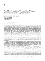
The Nernst law relates the potential of an electrochemical cell (E, in mV) to
the activities (a
i
, a
j
) of a given species in the two halves of the cell, illustrated
in Fig. 1.
E ¼
R ÁT
n ÁF
ln
a
1
a
2
ð1Þ
This equation can be converted to use logarithms to the base 10, in which
case the constant term is multiplied by 2.3 to become 0.059/n volts at room
temperature, where n is the number of electrons involved in the electro-
chemical oxidation/reduction of the species. In dilute solutions, activities
can be taken as equal to concentrations, so the equation takes on a simple
practical significance. Instruments such as pH meters that have a
temperature compensation circuit simply change the slope factor RT/nF
and do not take into account any changes in potential due to the chemistry,
such as changes in solubilities.
112 Marr
TM
Copyright n 2004 by Marcel Dekker, Inc. All Rights Reserved.
Figure 1 indicates that we require a means of connecting our potential-
measuring device, such as a digital voltmeter, to the two solutions. The
two electrodes, shown as silver wires in Fig. 1, serve this purpose, and
when coated with silver chloride and kept in a potassium chloride
solution of constant concentration, they maintain constant potentials.
Any difference in the two potentials is then taken up as a small constant
included in Eq. (1).
There are a number of practical points which arise from this
simple idea:
The membrane separating the two halves of the cell should be ideal
and respond only to the ion of interest (here the hydrated proton, H
þ
aq
). The
success of modern ion-selective electrodes derives from the ingenuity of
chemists in developing a range of membrane systems that come close to
meeting this requirement (Vesely et al., 1978).
No current should flow through this cell, as this would entail flow of
the ions through the membrane. The digital voltmeter must therefore have a
high input impedance, taking no more than a few pA of current from the
cell.
Sufficient ions should be available in the two solutions to enable the
membrane to respond to them. Measurements in very dilute waters are, for
this reason, rather difficult and will certainly entail a longer equilibration
time, say 1–2 minutes, till a stable potential is obtained.
Two electrodes are always required for potentiometry, even when it
appears, at first sight, that the measurement can be made with only one, as is
the case with combination pH electrodes (see below). The internal reference
electrode is usually not accessible to the user, but the external one must be
maintained by topping up with the electrolyte from time to time. A
saturated calomel electrode (see below) is frequently used as a separate
external reference electrode, and if the presence of traces of chloride is
undesirable, then the sulfate version can be used instead.
Figure 1 Schematic diagram of a Nernstian concentration cell with membrane.
Electroanalytical Methods 113
TM
Copyright n 2004 by Marcel Dekker, Inc. All Rights Reserved.
A. The Glass Electrode—Measurement of pH
Much research has gone into the development of special glasses for the glass
electrode, but the key to modern electrodes lies in the substitution of lithium
in the glass for sodium, to avoid the electrode responding better to the
sodium ions at high pH than to the very dilute hydrogen ions. Few users
these days ever think of the ‘‘alkali error’’ associated with electrodes
fabricated from Macinnes and Dole’s soda glass in 1930, and we can expect
a working range from pH 1 to pH 13, with deviations becoming significant
only outside this range, using the lithia–lime glass developed by Cary and
Baxter in 1949. Everything you could possibly need to know about the glass
electrode has been summarized excellently by Galster (1991).
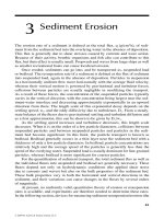
A modern combination pH electrode is shown in Fig. 2, and a
schematic diagram of the glass membrane in Fig. 3. The body may be glass or
glass sheathed in plastic for greater robustness. The bulb is sometimes
surrounded by a plastic protecting shield to minimize the chances of breaking
it by rough contact against sample containers. However, this impairs the
accessibility of the electrode surface to the ions in the solution and calls for
either good stirring of the solution or longer waiting time until the reading is
taken. Further, great care is then necessary to ensure that the electrode is
thoroughly washed, e.g., with a jet of distilled water, between samples.
Glass electrodes will give excellent service for a working life of one to
two years if looked after. A few important points should be remembered:
The glass membrane is thin (ca. 50 mm) and is easily scratched or
broken, especially if used to stir crystals when making up solutions.
The membrane will change irreversibly if allowed to dry out, though if
caught in time, an overnight soak in 1 M hydrochloric acid might rejuvenate
the very thin hydrated gel coating.
Figure 2 Combination glass electrode.
114 Marr
TM
Copyright n 2004 by Marcel Dekker, Inc. All Rights Reserved.
The potential should stabilize in 15–30 seconds after immersion in a
sample solution. Slower response may indicate that the electrode is nearing
the end of its useful life. At the same time the Nernstian response is also
beginning to be lost. For this reason, pH meters that permit the meter plus
electrode to be checked and adjusted in two different buffers are always to be
preferred. However, apparently slow response may be due to the behavior of
the sample: outgassing of CO
2
from some water samples may cause the pH
to drift upwards because the pH really is changing.
A pH electrode should always be checked against two buffers—even
an electrode with a hole in it can be made to read pH 4, but will read that
same value in all solutions.
The 0.05 M potassium hydrogen phthalate (10.2 g L
À1
) buffer with
pH ¼4.00 and the 0.05 M sodium tetraborate buffer (19.1 g L
À1
) buffer with
pH ¼9.20, both at 20
C, are reliable and easy to prepare one-component
buffers. Make them up fresh each week, as they are likely to deteriorate
owing to bacterial growth and to absorption of CO
2
from the air,
respectively.
B. ISFET pH Sensors
Transistors are three-electrode electronic devices in which a small current
flowing between two of the electrodes (emitter to collector) is controlled by a
second, very small, current flowing between the emitter and a third,
intermediate, electrode called the base. In a field-effect transistor (FET), the
controlling electrode responds to potential, normally generated by the
adjacent electronic circuitry, but sometimes by the external signal to be
measured, for example a potential generated by a chemical electrode. Thus
pH meters now use a metal oxide semiconductor FET (MOSFET)
operational amplifier to measure the potential of the glass electrode
without taking any current from it. The extension of the MOSFET
concept has been to coat the metal oxide layer with a chemically selective
coating – the ‘‘membrane’’ of a chemical electrode – and to allow a carefully
Figure 3 Schematic diagram of the glass membrane in a pH electrode. Shaded
area: dry glass membrane electrode for fluoride.
Electroanalytical Methods 115
TM
Copyright n 2004 by Marcel Dekker, Inc. All Rights Reserved.
chosen chemical system to control the transistor current. Such a device
has been termed a CHEMFET, a chemically sensitive field-effect transistor,
but now is more usually given the name ISFET, ion-selective field-effect
transistor (Bergveld, 1972). A silicon nitride coating, for example, deposited
on the metal oxide gate results in a device that has near ideal response to
hydrogen ions, with a working range of pH 1–13, and that is a great deal
tougher than any glass electrode. Mettler-Toledo and Thermo-Russell
market ISFET pH electrodes for demanding environmental applications,
but they can be used only with appropriate ISFET meters and not
with conventional pH meters.
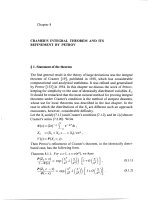
C. Single-Crystal Lanthanum Fluoride
Frant and Ross’s announcement in 1966 that doping LaF
3
with a little EuF
2
resulted in a single crystal with sufficient electrical conductivity to be used as
an electrode membrane, and one that would respond ideally to fluoride ions
in solution, represented a major breakthrough in the area of ion-selective
electrodes, much valued because of the difficulty at that time of determining
this anion by any other route (Frant and Ross, 1966). The construction is
shown in Fig. 4. One crucial practical problem was how to cement the LaF
3
single crystal to the plastic body and at the same time to guarantee perfect
electrical insulation. Users should be warned that single crystals are brittle
and will shatter if dropped on a hard surface.
The behavior of this electrode is worth discussing because it illustrates
problems common to most other electrodes, and also ways of overcoming
these problems.
Hydrofluoric acid, HF, is a weak acid, with pK
a
¼3.5, and the
electrode responds to the hydrated fluoride ion. Therefore all solutions must
be adjusted to a pH of 5 or greater, where the acid is effectively fully
dissociated. An acetate buffer is therefore added to all solutions, standards
and samples alike.
Figure 4 Single-crystal membrane electrode for fluoride.
116 Marr
TM
Copyright n 2004 by Marcel Dekker, Inc. All Rights Reserved.
As mentioned earlier, in high salt concentrations, ion activities deviate
significantly from analytical concentrations and calibrations based
on concentration, even for low fluoride concentration, and become
inaccurate. The answer is to add a high concentration of sodium perchlorate
to all solutions, to maintain a constant electrolyte strength for all
measurements.
Certain metal ions, notably aluminum and iron(III), form very stable
fluoride complexes and will effectively mask free fluoride in e.g. a river water
sample, so that very low fluoride concentrations will be reported if the
measured potential is converted to fluoride concen tration. The answer
here is to add a strong complexing agent, EDTA or CHDTA, to mask the
metal ions.
The fluoride electrode is therefore used with TISAB (total ionic strength
adjuster buffer) being added to all solutions, making possible a working
range of 0.1–100 mg L
À1
of fluoride (Frant and Ross, 1968). As the Nernst
equation is operative, the potential, in mV, is plotted against the log
10
of the
concentration, either in mg L
À1
or as molarity (Fig. 5).
D. Silver Halide in Silicone Rubber Membranes
The concept of using a sparingly solubl e metal salt as the responsive
component of a membrane lies behind the design of many types of electrode,
and the silver halides are the obvious choices for making a halide ion
selective electrode. The problem of making a ‘‘membrane’’ that was both
mechanically strong and electrically conducting was solved by Pungor et al.
(1966) by compressing finely powdered silver halide with a small amount of
Figure 5 Typical calibration for determination of fluoride with a LaF
3
electrode.
Electroanalytical Methods 117
TM
Copyright n 2004 by Marcel Dekker, Inc. All Rights Reserved.
silicone rubber as binder. Nernstian response was obtained over useful
working ranges for chloride, bromide, and iodide, but there is a degree of
response to other halides best described by the interion response factor:
E
cell
¼E
const
þ2:3
RT
nF
ln½a
i
þK
i,j
ða
j
Þ
For good performance and little interference, the K values should be small,
ideally 0.001 or less. General problems with ISEs and how to characterize
their performance have been discussed by Moody and Thomas (1972).
The sulfide electrode presents some difficulties in use, as free sulfide ion
is obtained only at very high pH, where oxidation of the ion is facilitated.
The standard procedure is to use a high pH buffer (1 M NaOH, ca. pH 14)
with an oxygen scavenger such as cresol, but this usually is a messy solution
that covers the electrode in oxidation products. It is also no solution to the
problem of measuring sulfide directly in sediments, where depth profiles are
of interest in investigations of the microbial mat and the pore water
composition changes in composition with depth. However, as the main
interference is a pH effect, it can be countered by measuring the pH and
correcting the sulfide electrode potential directly, with a series of calibration
graphs covering the pH range of interest (Fig. 6).
E. Liquid Ion Exchanger Membranes for Anions
Liquid ion exchangers can be held on porous glass or ceramic supports to
serve as membranes for ion-selective electrodes but are nowadays more
commonly mixed in with a polymer to give a solid plastic membrane,
enabling a large variety of chemistries to be utilized. Long-chain quaternary
amines are dissolved in a viscous solvent as their ion pairs, e.g.,
cetyltrimethylammonium cation with nitrate or perchlorate, offering good
selectivity, especially for larger single-charged anions. Generally one makes
the assumption that interfering ions will not be present in the test sample, as
for example perchlorate when an electrode is being used to monitor nitrate
Figure 6 Sulfide calibrations recorded at different pH values.
118 Marr
TM
Copyright n 2004 by Marcel Dekker, Inc. All Rights Reserved.
in river water. These electrodes require attention, with regular replacement
of the liquid, but are nevertheless useful for environmental monitoring
purposes, covering as they do the concentration range of interest.
F. Plastic Membranes for Cations
Early investigations in the 1960s showed that metal ions immobilized in a
PVC (polyvinyl chloride) matrix, as sparingly soluble salts, could behave as
selective membranes. These offer the advantage of simplicity of replacement
compared with the liquid ion exchanger membranes. Successful calcium
electrodes, for example, were made by incorporating the calcium salt of
didecylphosphoric acid along with neutral dioctylphenylphosphonate as
modifier, in PVC (Crags et al., 1974). Much research has subsequently
gone into designing highly specific ligands for a range of metals, in which
the dimensions of the chelate formed when the long-chain arms wrap
around the metal ion approach the ideal for the particular metal ion.
G. Electrodes for the Alkali Metals
Glass electrodes were originally explored for determination of the alkali
metals, especially sodium and potassium, particularly with medical applica-
tions in mind. However, though a glass electrode for sodium has long been
marketed and is useful in that sodium is usually present, at least in physio-
logical fluids, at one hundred times the concentration of potassium, so that
potassium does not cause a significant interference, the complementary
problem of the determination of potassium seemed insoluble. It was only
when Simon and his team (1970) showed that complexes between certain
antibiotics and potassium were so much more stable than the corresponding
ones with sodium, that a really selective electrode could be manufactured.
Valinomycin, a cyclic 6-membered peptide that displays a selectivity constant
with a factor of three to four thousand in favor of potassium against
sodium, has formed the basis of a range of successful commercial electrodes.
The combination of reagents is formulated into a plastic membrane.
H. Gas-Sensing Electrodes
Electrodes are commercially available for a few gases—ammonia and
carbon dioxide in particular. In fact, they do not respond in the way that the
ion-selective electrodes do but are pH electrodes covered with special
coatings, often of silicone rubber, that offer selective permeability to the gas
in question. Thus ammonia arriving at the glass electrode surface causes a
rise in pH, whereas carbon dioxide causes a lowering. The working ranges
are much smaller than those of the true ion-selective electrodes.
Electroanalytical Methods 119
TM
Copyright n 2004 by Marcel Dekker, Inc. All Rights Reserved.
I. General Comments on ISEs
Because the response of an electrode to the determinant is logarithmic,
establishing the limit of detection is a little more difficult than for linear
response systems. Midgley (1984) has discussed this matter, showing
how the intersection of the sloping line and the low-level constant
potential can help. Technical data in Table 1 show that a wide range of
electrodes is available, for many common ions, covering concentrations of
interest in environmental work as well as in many medical applications. The
advantages of such probes include
The simplicity of a direct reading device requiring little or no chemical
sample treatment
A wide working range, typically three orders of magnitude
Reasonable tolerance to other ions in many environmental samples
Suitability for continuous monitoring using data loggers to collect
measurements
The possibility of being made with very small dimensions for exploring
concentration profiles, e.g., in tissue or in sediment
J. Redox Electrodes
Noble metal electrodes respond to the redox potential of their environment
without actually dissolving or corroding, a fact frequently made use of for
assessing the state of the chemistry in, e.g., sediment pore water. A 1-mm
diameter platinum wire is sealed into an insulating sheath and can then be
pushed into a wet sediment with little risk of breakage. Redox electrodes are
Table 1 Examples of Ion-Selective Electrodes
Species Type Range (M) Species Type Range (M)
Ammonia gas 5Â10
À7
to 1 Iodide solid-state 5 Â10
À8
to 1
Bromide solid-state 5 Â10
À6
to 1 Lead solid-state 10
À6
to 0.1
Cadmium solid-state 10
À7
to 0.1 Nitrate plastic 7 Â10
À6
to 1
Calcium plastic 5 Â10
À7
to 1 Nitrite plastic 4 Â10
À6
to 10
À2
Carbon
dioxide gas 10
À4
to 10
À2
Perchlorate plastic 7 Â10
À6
to 1
Chloride solid-state 5Â10
À5
to 1 Potassium plastic 10
À6
to 1
Copper solid-state 10
À8
to 0.1 Sulfide solid-state 10
À7
to 1
Cyanide solid-state 8 Â10
À6
to 10
À2
Sodium glass 10
À6
to 1
Fluoride
solid-state
crystal 10
À6
to 1 Thiocyanate solid-state
5 Â10
À6
to 1
Source: Data from Thermo-Orion (2001) and from Metrohm (1999).
120 Marr
TM
Copyright n 2004 by Marcel Dekker, Inc. All Rights Reserved.
small, cheap, robust, and easily cleaned. Sediment cores for study in the
laboratory can be filled into lengths of 6-cm plastic drainpipe, through the
side of which, at regular intervals, are drilled holes just large enough for a
micro redox electrode to be inserted and left for the duration of the
experiment. The redox potential is a property of the solution, but it will be
controlled by one chemical system (the predominating one) and be at the
same time indicative of all others in the same solution. As iron is commonly
present in sediment pore waters, has two readily acccessible oxidation states
in solution, and does not show inhibiting kinetic effects, it is probably the
indicating species, so that
E
measured
¼E
þ 2:3
RT
nF
log
½Fe
3þ
aquo
½Fe
2þ
aquo
As anaerobic bacterial activity increases and diffusion of oxygen into
the pore water decreases, so the potential falls, controlled by the iron system
and indicating the state of balance of other chemical couples. Interpretation
of the measured E
h
values is, however, complicated because the standard
potentials of the different couples are all pH dependent. An idea of the
values that may be expected in soils is given by the selected potential values
in Table 2 (Cresser et al., 1993).
K. Reference Electrodes
Any measurement of potential is in fact one of potential difference between
two electrodes, so an appropriate second electrode must always be selected,
Table 2 Eh Values for Important Redox Reactions in Soils and
Sediments
Reaction Eh (mV) at 25
C
pH 5 pH 7
O
2
to H
2
O 930 820
NO
3
À
to NO
2
À
530 420
MnO
2
to Mn
2þ
640 410
Fe(OH)
3
to Fe
2þ
170 À180
SO
4
2À
to S
2À
À70 À220
CO
2
to CH
4
À120 À240
H
2
OtoH
2
À295 À413
Note: Potentials are with respect to the standard hydrogen electrode.
Source: Cresser et al., 1993.
Electroanalytical Methods 121
TM
Copyright n 2004 by Marcel Dekker, Inc. All Rights Reserved.
the potential of which must remain invariant, and preferably known,
throughout the duration of the experiment. Reference electrodes make use
of a single metal—usually silver or mercury—immersed in a solution of its
ions. The form of the Nernst equation appears then slightly different from
that for the concentration cell used to describe the behavior of ion-selective
electrodes, as one of the oxidation states is now zero, that of the pure metal
itself (which is not in solution):
E
measured
¼ E
þ 2:3
RT
nF
log½Ag
þ
aquo
It would in practice be difficult to ensure that the solution being
measured always contained the same concentration of silver ions, so two
steps are taken:
1. A separate chamber is constructed around the silver wire, containing the
salt solution
2. A sparingly soluble silver salt is chosen—normally the chloride—and the
electrolyte in the chamber, potassium chloride, is maintained at a
constant, relatively high (say 0.1 M or 1 M ) concentration.
The silver concentration is then governed by the chloride concentration, since
K
sp
¼½Ag
þ
aquo
Á½Cl
À
aquo
¼10
À9:5
at ionic strength ¼ 1
The chamber surrounding the silver wire electrode is designed to have
a small leak, such as a porous ceramic plug fused into the wall of the
chamber, permitting electrical contact to be made with the sample solution.
The more porous the plug, the faster the electrode cleans itself of any sample
contamination, but the more often the electrolyte must be topped up to
make good the loss. The silver electrode is the standard partner for all pH
and ion-selective electrodes, and, as shown in Fig. 1 for glass pH electrodes,
it is usually constructed as a concentric annular chamber surrounding the
glass electrode itself. Clearly, for correct operation, both the glass bulb and
the porous plug must be below the surface of the test solution.
The second common choice for a reference electrode is the calomel
electrode, taking its title from the trivial name of mercury(I) chloride,
Hg
2
Cl
2
, also a sparingly soluble salt. The commonly used ‘‘saturated
calomel electrode’’ owes its name to the fact that the potassium chloride
filling electrolyte is saturated, as should always be apparent from the crystals
of that salt sitting inside the electrolyte chamber. The advantage of this
system is that it is easy to check that the solution is indeed saturated and to
know that the potential of the electrode will be that expected of it; the
(small) disadvantage is that the solubility of potassium chloride in water
122 Marr
TM
Copyright n 2004 by Marcel Dekker, Inc. All Rights Reserved.
increases markedly with temperature, so that the mercury(I) concentration
decreases correspondingly and the potential will decrease. For very precise
work, therefore, the 3 M potassium chloride calomel electrode, which does
not have the crystalline solid phase present, may be preferred.
Most reference electrodes are not designed to deliver much current—
the resistance of the porous plug is quite high and the area of the metal is
small—so reference electrodes for voltammetry must be designed differently
from those for potentiometry. Potentials of the common reference
electrodes, quoted with respect to the standard hydrogen electrode, are
summarized in Table 3.
III. AMPEROMETRY
A. Dependence of Current on Concentration
When a current is allowed to flow through an electrochemical cell, it will be
limited by one or more factors, primarily by the rate at which ions
(or, indeed, molecules) can be transported to an electrode surface, there to
undergo a redox reaction, but also by the electrical resistance of the system,
composed of electrolyte, membrane, and electrode. If the current is to be
taken as a measure of a concentration, then transport in the solution must
be the limiting factor, so that Fick’s laws of diffusion can be assumed to
hold, i.e. that the flow of analyte to the electrode is proportional to a
concentration gradient; and since the analyte is also assumed to react
completely at the electrode on arrival, that the concentration at the electrode
is therefore effectively zero, and the concentration gradient is dependent
only on the bulk concentration. We may summarize as follows:
1. Current is proportional to rate of arrival of determinand molecules/ions
2. Rate of transport is dependent on the concentration gradient near the
electrode
3. The concentration gradient is controlled by the bulk concentration
4. i ¼k Á[A], where i is the current, usually in microamperes, and [A] is the
concentration of the species being determined.
Table 3 Potentials of Some Common Reference Electrodes
Couple 3.5 M KCl Saturated KCl Saturated K
2
SO
4
Ag
þ
/Ag 205 199 —
Hg
2þ
2
/Hg 250 244 658
Note: Potentials are in mV, with respect to the standard hydrogen electrode.
Electroanalytical Methods 123
TM
Copyright n 2004 by Marcel Dekker, Inc. All Rights Reserved.
B. Dependence of Current on Potential—Polarography
There is, however, a second constraint, in that to effect oxidation or
reduction of the determinand at the electrode it will usually be necessary to
apply a potential, typically in the range up to Æ2 volts, determined by the
oxidation–reduction potential of the analyte couple. Just as with potentio-
metry, also in amperometry, a second electrode is required, often acting as
both counterelectrode (to carry the current) and reference electrode (to
enable the potential of the working electrode to be precisely defined). The
working electrode for polarography is the dropping mercury electrode
(DME), first pioneered for this purpose by Heyrovsky in 1922. While it is
bothersome to keep it in good working order, as the very fine glass capillary
blocks readily, the DME does possess several important properties:
1. Most metals dissolve in it to form amalgams, and so behave ideally
2. Hydrogen ions are reduced with difficulty, creating an overvoltage and
giving an enlarged potential window enabling more reactive metal ions,
such as zinc, to be reduced
3. The dropping electrode always has a clean, new surface, uncontaminated
by the products of electrolysis of the sample.
A polarographic procedure involves scanning a voltage range—s ay 0
to À2 volts—slowly, over a period of 2–3 minutes, while the electrode
releases one drop every 3–5 seconds, and recording the current (of the order
of microamps) flowing through the cell. The reference electrode is often a
saturated calomel electrode, but with a larger working area and lower
electrical resistance than the electrode used for potentiometry, so that it will
not be affected by the flow of currents up to 10 mA. This may be seen in a
classical polarogram, as shown in Fig. 7.
At low applied potentials, a very small current flows, due to unwanted
processes such as, in the case of classical polarography, the carrying of charge
by each mercury drop falling from the electrode capillary. As the electrode
potential for the determinand in question is approached—here Pb
2þ
aq
—lead
ions on the surface of the electrode are reduced to lead atoms, causing a flow
of electrons between electrode and solution, and the lead atoms dissolve in
the mercury drop electrode. The choice of this special electrode thus permits
a clean and reproducible surface to be maintained throughout the
experiment. As the potential E
applied
is further increased, the concentration
of lead ions at the electrode decreases (controlled by the Nernst equation)
and the transport rate increases, so that the current, i, also increases.
E
applied
¼ E
1
=
2
þ
0:059
n
log
10
ði
d
À iÞ
i
124 Marr
TM
Copyright n 2004 by Marcel Dekker, Inc. All Rights Reserved.
Eventually, the concentration at the surface of the electrode becomes
nearly zero and the transport of determinand, and hence the current flowing,
levels off, now controlled purely by the concentration gradient, obeying the
laws of diffusion. Purely, that is, as long as the solution is not stirred. In
classical polarography, the potential halfway up the ‘‘wave’’, E
½
, where
[Pb
2þ
] ¼ [Pb
0
], approximates to the electrode potential for lead and hence
serves to identify the element as lead (in this case), and the increase in
current—the diffusion current i
d
—serves to quantify its concentration in
solution. Here, the information content of a two-dimensional plot is seen to
be so much greater than that of a single potential measurement as in the case
of potentiometry. Indeed, if there are other reducible ions in the solution,
such as Cd
2þ
,Zn
2þ
, and others, they may be identified and quantified in the
same analysis—truly a multicomponent analysis of solutions.
1. Limits of Detection of Polarography
While the capabilities of classical polarography—facilitating identification
and quantification on multicomponent solutions—are clear from Fig. 8, so
also is the principal drawback. The dropping mercury electrode, while
guaranteeing a clean, reproducible surface, also guarantees a very noisy
signal due to the aforementioned drop charging effect, as a result of which it
is not practical to go below 10
À5
M for reliable analyses, i.e., 2 mg L
À1
for
lead, hardly sensitive enough for modern environmental analysis. Atomic
absorption spectrometry using a graphite furnace will go to one hundred
times lower than this, so that even with the improvements offered by
differential pulse polarography and some other variants, the technique has
Figure 7 Classical polarogram for lead and zinc ions.
Electroanalytical Methods 125
TM
Copyright n 2004 by Marcel Dekker, Inc. All Rights Reserved.
dropped out of use. But electroanalytical chemistry has another option,
which is second to none for low-level trace analysis, stripping voltammetry.
C. Anodic Stripping Voltammetry (ASV)
If a single mercury drop, produced by extrusion from a micrometer burette,
is held at a negative potential on the upper plateau of the pol arographic
‘‘wave,’’ the metal, such as lead, will be deposited and dissolved into the
mercury, being thus accumulated: the longer the period of electrolysis, the
greater will be the amount of metal collected. This amount is still
proportional to the bulk concentration, as well as to the deposition time.
After, say, ten minutes, the potential is scanned back towards zero, and at
around the half-wave potential the lead atoms will be ‘‘stripped’’ out of the
mercury drop, being oxidized back to soluble hydrated Pb
2þ
ions in
solution, and a current will flow. The current will be short-lived (say 10
seconds), but the peak current will be, in this case, sixty or more times
greater than during the deposition step, and it will not be superimposed on a
noisy background of the electrode drop charging current. Moreover, while
stirring is undesirable in classical polarography, it can greatly help the
transport of ions to the single drop electrode and give a corresponding
further increase in sensitivity. This is the principle of stripping voltammetry
(Neeb, 1969, 1989).
The single drop mercury electrode was originally proposed for
this technique by Kemula and Kublik (1958)—the hanging drop, and by
Neeb (1961)—the sitting or ‘‘sessile’’ mercury drop. However, there
Figure 8 DC anodic stripping voltammograms for lead with standard additions of
20 mgL
À1
; sample contained 5 mgPbL
À1
.
126 Marr
TM
Copyright n 2004 by Marcel Dekker, Inc. All Rights Reserved.
is a drawback to using the mercury drop—that of controlling its size and of
keeping it still. Large drops lead to wide stripping peaks, as it takes time for
the atoms to diffuse through the mercury back to the surface for oxidation
in the stripping process. The alternative is to use some other, solid,
electrode, but to prevent the effect of one metal ‘‘trapping’’ another on the
solid surface, it is coated with a thin film of mercury by simultaneous
electrodeposition during the preconcentration step, allowing each deposited
metal to behave independently during the stripping process. The glassy
carbon electrode is the solid material of choice, as it does not suffer from the
problems of adsorption of other chemically active species, especially oxygen,
into pores, such as occurs with ordinary graphite electrodes (Neeb, 1969).
Unfortunately, easy though the glassy carbon electrode is to use, the limits
of detection obtained using it (in the mercury film mode) are typically ten
times higher than those obtained with the hanging mercury drop extrusion
electrode. Typical stripping voltammograms, showing the sharpness of the
peaks, are shown in Fig. 8. Another variant, instead of stirring the solution,
is to rotate the electrode—using the so-called rotating disk electrode, which
may also be amalgamated during the deposition step.
Of course, several metals can be determined in one analysis, just as
with classical polarography; Cd, Cu, and Pb are the most important, from
dilute acid solution, and Zn from a buffered alkaline solution; so this
technique, getting down to 5–10 mgL
À1
, competes with GF-AAS as far as
sensitivity goes and wins as far as speed of analysis is concerned. A number
of interferences are known that arise due to the formation of sparingly
soluble intermetallic compounds in the mercury drop. Some are of little
importance, as they involve a noble metal such as gold, but a troublesome
combination is that of copper (or nickel) and zinc. Copper can be
determined from acid solution, leaving zinc in solution, but zinc must be
determined from an alkaline solution containing a little cyanide (the amount
is critical) to mask the copper and permit deposition of the zinc (Marques
and Chierice, 1991).
Finally, while some electrolyte must be present, to render the solution
electrolytically conductive, high salt concentrations are actually welcome, as
they guarantee diffusion control of transport and eliminate any charge-
dependent transport effects. But at higher salt concentrations the diffusion
coefficients of the determinand ions will become less, resulting in a variable
calibration factor. The answer is to use the standard addition technique—
recording first the voltammogram for the sample itself, then again, after one
and two additions of known amounts of the element(s) in question. Such in
situ calibration (Fig. 8) overcomes many uncertainties and is to be strongly
recommended for environmental analysis.
Electroanalytical Methods 127
TM
Copyright n 2004 by Marcel Dekker, Inc. All Rights Reserved.
Limits of detection depend on the one hand on contamination—so
great attention must be paid to acid cleaning of all apparatus including the
sample bottles, as well as to choice of any reagents added—and on the other
hand to sloping baselines due to other species in solution. This problem can
be overcome by using differential pulse measurement during the scan, rather
than simple DC measurement, taking limits of detection for lead, for
example, down from around 1 mg/L with DC scanning, to one hundred
times less with DP scanning voltammetry. So now we have a clear winner,
mgL
À1
or even ng L
À1
concentrations can be determined directly in
seawater, eliminating the need for any sample pretreatment and the
associated risks of introducing contamination. The determination of several
metals in seawater by several approved polarographic methods has been
reviewed (Standing Committee of Analysts, 1987a). Details of determina-
tions of Cd and Pb using ASV are summarized in Table 4.
D. Cathodic Stripping Voltammetry (CSV)
Not all metals are easily reduced onto a mercury electrode, but the two-step
approach can be modified to cope with a number of other metals, by making
use of adsorption of the desired metals species, as sparingly soluble
compounds, often as organic chelates. These are then reduced during a
potential sweep step, allowing the metals to be transferred to the mercury
drop. This is particularly important for metals which are not normally
readily reduced at a mercury electrode, such as aluminum, vanadium, and
uranium. Accumulation is still diffusion-controlled (and assisted by
controlled stirring), so that the resulting peaks are proportional to the
initial concentration in the sample solution. Details of some determinations
using CSV are also summarized in Table 4.
1. Sample Preparation—UV Photolysis
While it has been mentioned that ASV and CSV offer the attraction of being
directly applicable to the analysis of very dilute aqueous samples, with little
or no sample pretreatment, the prob lem of interference from high-
molecular-weight organic materials should be mentioned. Surface-active
subtances collecting on the surface of the electrode will significantly affect
the stripping voltammograms—sloping baselines and broadened peaks
result, making reliable quantitation difficult. Irradiation of the sample
solutions, in quartz test tubes set around a high-power mercury vapor UV
lamp (typically 500 W, e.g., the Metrohm model 705 UV Digester) for 30
minutes will usually solve this problem. UV irradiation will also break down
any organic complexing ligands, releasing the metals into the (acidified)
128 Marr
TM
Copyright n 2004 by Marcel Dekker, Inc. All Rights Reserved.
Table 4 Determination of Some Trace Metals in Seawater by Stripping Voltammetry
Element Technique Reagent Peak potential, V Limit of detection Upper working limit
Al DP-CSV Alizarin Red S, pH 7.1 À1.13 30 ng L
À1
10 mgL
À1
Cd þPb DP-ASV pH 2.8 with HCl À0.7 10 ngL
À1
50 mgL
À1
Co þNi CSV Dimethylglyoxime, pH 8.3 À1.13 10 ng L
À1
60 mgL
À1
Cu DP-CSV Catechol, pH 7.5 À0.27 5 ngL
À1
10 mgL
À1
Fe CSV 1-Nitroso-2-naphthol, pH 6.9 À0.53 60 ng L
À1
2 mgL
À1
Ni CSV Dimethylglyoxime, pH 8.3 À1.01 10 ngL
À1
60 mgL
À1
Pb DP-ASV pH 2.8 with HCl À0.5 30 ngL
À1
50 mgL
À1
U CSV 8-Hydroxyquinoline, pH 6.9 À0.68 50 ng L
À1
10 mgL
À1
V DP-CSV Catechol, pH 6.9 À0.69 15 ngL
À1
50 mgL
À1
Zn DP-CSV
Ammonium pyrrolidone
dithio-carbamate, pH 7.3 À1.15 10 ng L
À1
10 mgL
À1
Note: All determinations done using a dropping mercury electrode. Source: Standing Committee of Analysts, 1987a.
Electroanalytical Methods 129
TM
Copyright n 2004 by Marcel Dekker, Inc. All Rights Reserved.
TM
Copyright n 2004 by Marcel Dekker, Inc. All Rights Reserved.
solution (Standing Committee of Analysts, 1987a). The initial volume of
solution in the tube should be noted, and the loss of water occurring during
this pretreatment made good after cooling.
Finally, one special advantage of ASV should be mentioned: its unique
role in speciation. While filtration is normally used, e.g., with 0.45 mm
membrane filters, to separate suspended solids from ‘‘soluble’’ forms of an
element in a natural water sample, the question of colloidal material is
conveniently overlooked. This would pass through such a filter, and be
determined by flame or plasma spectroscopic methods, but would not be
detected by stripping voltammetry, which ‘‘sees’’ only genuinely soluble
forms of the element being determined.
E. Voltammetry of Nonmetals
A very exciting development in environmental electroanalytical chemistry
has been the new voltammetric methods enabling speciation of sulfur
compounds in sediments to be studied. Luther and coworkers (2001) have
used solid gold amalgams to probe bacterial mats on sediments, and from
the very fast (1,000 mV s
À1
) cyclic voltammograms they have been able to
distinguish not only ionic forms such as sulfide and thiosulfate but also
elemental sulfur, with 0.5 mm resolution in depth. One of these electrode
systems has been fitted to a deep ocean lander to investigate the sulfur
speciation around deep-sea hydrothermal vents. A cyclic voltammogram
showing peaks for several sulfur species is shown in Fig. 9.
F. Determination of Dissolved Oxygen
In the realm of classical polarography, dissolved oxygen was the
omnipresent problem. The well understood reduction first to peroxide and
then to water, giving two polarographic waves, necessitated removal of the
Figure 9 Cyclic voltammetry trace for sulfur species in a salt marsh microbial mat.
(From Luther et al., 2001.)
130 Marr
TM
Copyright n 2004 by Marcel Dekker, Inc. All Rights Reserved.
oxygen by bubbling an inert gas through the solution to displace the oxygen,
according to Henry’s law—if there is no oxygen in the gas phase over the
solution, then there should be none in the solution. On the other hand,
portable polarographs with polished mahogany cases to contain the
apparatus and the dropping mercury electrode were used in the field and
proved the point that samples that could not be transported back to the
laboratory could nevertheless be analyzed.
Measurement of dissolved oxygen (DO) in natural surface waters is
important, as it is a key indicator of water quality, and is included, for
example, in arriving at the Solway Water Quality Index for an environ-
mental sample (Bolton et al., 1978). What is often forgotten by chemists is
that in any but the cleanest waters, the dissolved oxygen level does not
remain steady but increases during the day, owing to photosynthesis by
algae and plants; and it decreases at night, owing to the respiration of
bacteria and algae. A third factor contributing to the changes is the transfer
between the water and the air, which works in either direction depending on
the concentration in the water in relation to the DO saturation level, and
which depends mainly on the perturbation of the surface by wind action
(Ansa-Asari et al., 1999). There are two approaches to dealing with this
difficulty—sample at the same time each day, and measure in the field. It is
best to measure directly in the water body itself, to avoid disturbing the
oxygen, particularly when the water is supersaturated, as will be the case in
the late afternoon, or to monitor round the clock and analyze the changing
signal to give a measure of the three different activities mentioned above. In
either case, a small portable measuring device is required.
The development by Mackereth (1964) of an alternati ve electroche-
mical cell (to the dropping mercury electrode) solved the practical problems
and gave the analyst a valuable tool for environmental analysis. Oxygen
diffuses from the test solution through a polymer membrane (often PTFE)
into a small volume of electrolyte (such as potassium carbonate) in which are
immersed two electrodes—a silver–lead pair or a gold–silver pair (Fig. 10).
Figure 10 Mackereth cell for determination of dissolved oxygen (DO).
Electroanalytical Methods 131
TM
Copyright n 2004 by Marcel Dekker, Inc. All Rights Reserved.
The overall reaction of Pb þO
2
! PbO
2
takes place in two steps,
made possible by a flow of current through the external circuit: Reduction of
oxygen takes place at the silver electrode:
O
2
þ 4e
À
þ 2H
2
O ! 4OH
À
and oxidation of the lead takes place at the other electrode:
Pb þ4OH
À
! PbO
2
þ 2H
2
O þ4e
À
The current depends on the rate of diffusion of oxygen into the cell,
which in turn is dependent on the concentration in the sample solution, or,
more strictly, on the concentration in the water at the surface of the
membrane. If there is no movement of the water, the DO concentration
at the membrane surface becomes depleted and the current falls. In
the laboratory, a small stirrer is incorporated to ensure a steady and
reproducible movement of the water and hence a reproducible response
from the device. In a river, the motion of the water may suffice, but in a lake
or pond the response will be low and the calibration will not be reliable.
Calibration is often achieved simply by setting the response to 100%
of saturation by holding the probe in air, on the assumption that the DO
level in solution will equate to that partial pressure in equilibrium with air.
In practice, while this is very convenient, it should not be trusted too far,
and all oxygen probes should be checked on a series of test solutions from
which differing amounts of oxygen have been displaced by bubbling
nitrogen for some minutes. The actual DO levels should be determined by
the Winkler titration method, and calibrations constructed for each probe.
Experience has shown that response factors for probes do vary from probe
to probe and that such calibration is necessary. Some commercial DO
probes and meters (e.g., the Russell RL series) incorporate not only
temperature correction but also a salinity correction.
To sum up, whatever be the difficulties with lifetimes of membranes
and probe capsules, and of calibration, the modern DO probe is an
invaluable tool for use not only in the laboratory but also in the field, for the
direct measurement of true dissolved oxygen concentration from the surface
down to depths of several meters, even in highly supersaturated waters
(Standing Committee of Analysts, 1987b).
DO Measurements in Sediments. There has been increasing interest
over the last twenty years in the study of marine sediments at great depths —
in principle an ideal application for electrochemical probes. The problem of
trying to measure DO gradients through short distances, as in microbial
mats on the surface of sediments, and to do so without the possibility of
132 Marr
TM
Copyright n 2004 by Marcel Dekker, Inc. All Rights Reserved.
stirring, led to the development of microelectrodes (Revsbech et al., 1980),
but they tended to be delicate and easily broken. A new idea employs
quenching of a dyestuff fluorescence by dissolved oxygen, realized by a
‘‘micro-optrode’’ in which exciting and emitted light is transmitted through
fiber optics in a very rugged miniaturized construction. Such a device has
been shown to work well at depths of over 10 m, and still with a depth
resolution in the sediment of 0.1 mm (Glud et al., 1999).
IV. CONDUCTIVITY
Measurement of electrical conductivity of a water sample serves simply
to give an indication of the levels of dissolved salts present and does not of
itself contribute any chemical information about the sample. The specific
conductance of a solution, k, is the electrical conductivity of a 1-cm cube with
1-cm
2
electrodes on opposite faces. Hence, for a practical measurement using
a conductivity cell, with plates (electrodes) of area A and separated by a dis-
tance d, the measured conductance s (reciprocal of the resistance in ohms) is
¼ Á
A
d
The old term mho for reciprocal ohm is now superseded by the siemen,
S, so that the specific conductivity k of a solution has the units of S cm
À
1.
Conductivity cells have dimens ions close to, but not the same as, those
referred to in the definition. Accordingly, each cell will have its ‘‘cell
constant’’ ¼d/A stamped on it. Hence k¼s Á. The two electrodes,
enclosed in a small chamber with openings at either end permitting rapid
flushing of the cell, but minimizing the contribution of a ‘‘round the back’’
conductivity, may be platinum sheet supported on the glass, but in some
cases they are coated with finely electrodeposited platinum black.
Measurement makes use of a traditional Wheatstone bridge circuit, but
one which is supplied with a small AC voltage to minimize buildup of
products of electrolysis of the sample solution. Frequencies may be 50 Hz
(for low conductivities) or, preferably, 1 kHz (for higher conductivities
where the greater capacitance contribution will be less important).
The conductance of a salt solution varies with temperature, increasing
by about 2–3% per degree. For good results, therefore, temperature control
must be employed, especially where the conductivities of different solutions
are to be compared. Good practi ce will therefore include a check on the
conductivity of a potassium chloride solution: a 0.005 M solution
(0.373 g L
À1
) will have a specific conductivity of 654 mScm
À1
at 20
C
(Standing Committee of Analysts, 1978).
Electroanalytical Methods 133
TM
Copyright n 2004 by Marcel Dekker, Inc. All Rights Reserved.
An interesting application of conductivity measurement is to estuarine
waters, where the boundary between the upper (river water) and lower
(seawater) layers can often be sharply defined. A very special application,
calling for great precision and demanding great care in experimental
measurement, is the determination of the slight variations in salinity of
different seawater samples, discussed in some detail by Grasshoff et al. (1999).
V. CONCLUSIONS
It will have become clear to the reader that the techniques described in this
chapter have been in routine use for many years and are well established and
well documented. While many older electroanalytical procedures described
in textbooks have fallen out of use, a small number of new approaches are
now making possible automated remote measurements in inaccessible
locations such as the ocean floor, thus helping to retain an important role
for electroanalytical techniques in environmental analysis.
REFERENCES
Ansa-Asari, O., Marr, I.L. and Cresser, M.S. 1999. Evaluation of cycling patterns of
dissolved oxygen in a tropical lake as an indicator of biodegradable organic
pollution. Sci. Total Environ. 231:145–158.
Bergveld, P. 1972. Development, operation and application of the ion-selective field-
effect transistor as a tool for electrophysiology. IEEE Trans. Biomed. Eng.
19:340–354.
Bolton, P.W., Currie, J.C. and Tervet, D.J. 1978. An index to improve water quality
classification. Water Pollut. Control 271–284.
Crags, A., Moody, G.J. and Thomas, J.D.R., 1974. PVC matrix membrane ion-
selective electrodes. J. Chem. Ed. 51:541–544.
Cresser, M.S., Killham, K. and Edwards, T. 1993. Soil Chemistry and Its
Applications. Cambridge University Press, Cambridge.
Frant, M.S. and Ross, J. W. 1966. Electrode for sensing fluoride ion activity in
solution. Science 154:1553–1555.
Frant, M.S. and Ross, J. W. 1968. Use of a total ionic strength adjustment buffer for
electrode determination of fluoride in water supplies. Anal. Chem.
40:1169–1171.
Galster, H. 1991. pH Measurement. Verlag Chemie, Weinheim.
Glud, R.N., Klimant, I., Holst, G., Kohls, O., Meyer, V., Ku
¨
hl, M. and Gundersen,
J K. 1999. Adaptation, test and in situ measurements with O
2
microoptrodes
on benthic landers. Deep-Sea Research I 46:171–183.
Grasshoff, K., Kremling, K. and Ehrhardt, M. 1999. Methods of Seawater Analysis.
3d ed. Wiley-VCH, Weinheim.
134 Marr
TM
Copyright n 2004 by Marcel Dekker, Inc. All Rights Reserved.
Kemula, W. and Kublik, Z. 1958. Application de la goute pendante de mercure a
`
la
de
´
termination de minimes quantite
´
s de differents ions. Anal. Chim. Acta
18:104–111.
Luther, G.W., Glazer, B.T., Hohmann, L., Popp, J.I., Taillefert, M., Rozan, T.F.,
Brendel, P.J., Theberge, S.M. and Nuzzio, D.B. 2001. Sulfur speciation
monitored in situ with solid state gold amalgam voltammetric microelectrodes:
polysulfides as a special case in sediments, microbial mats and hydrothermal
vent waters. J. Environ. Monit. 3:61–66.
Mackereth, F.J.H. 1964. Improved galvanic cell for determination of oxygen
concentration in fluids. J. Sci. Instrum. 41:38–41.
Marques, A.L.B. and Chierice, G.O. 1991. Elimination of copper–zinc interference in
ASV by addition of a complexing agent. Talanta 38:735–739.
Metrohm Ltd. 1999. Metrosensor Electrodes Catalogue. Metrohm Ltd., CH-9101
Herisau, Switzerland.
Midgley, D. 1984. Limits of detection of ion-selective electrodes. Anal. Proc.
21:284–287.
Moody, G.J. and Thomas, J.D.R. 1972. Development and publication of work with
selective ion-sensitive electrodes. Talanta 19:623–639.
Neeb, R. 1961. Anodische amalgamvoltammetrie: III. Comparison of amalgamated
platinum and stationary mercury electrodes. Z. Anal. Chem. 180:161–168.
Neeb, R. 1969. Inverse Polarographie und Voltammetrie. Verlag Chemie, Weinheim.
Neeb, R. 1989. Stripping Voltammetry. Metrohm Ltd., CH 9101 Herisau, Switzerland.
Pungor, E., To
´
th, K. and Havas, J. 1966. Theorie und Anwendung der heterogen
Gummimembranelektroden fu
¨
r die Bestimmung einiger Ionen. Mikrochim.
Acta 689–698.
Revsbech, N.P., Jørgensen, B.B. and Blackburn, T.H. 1980. Oxygen in the sea
bottom measured with a microelectrode. Science 207:1355–1356.
Simon, W., Wuhrmann, H R., Vasak, M., Pioda, A.R. and Stefanac, Z. 1970. Ion-
selective sensors. Angew. Chem. Int. Ed. Eng. 9:445–455.
Standing Committee of Analysts. 1978. Measurement of Electrical Conductivity and
Laboratory Determination of the pH Value of Natural, Treated and Waste
Waters. HMSO, London.
Standing Committee of Analysts. 1987a. Determination of Twelve Trace Metals in
Marine and Other Waters by Voltammetry or AAS. HMSO, London.
Standing Committee of Analysts. 1987b. Dissolved Oxygen in Natural and Waste-
waters. HMSO, London.
Thermo-Orion. 2001. Laboratory Products Catalogue. Thermo-Orion, Beverly, MA,
U.S.A.
Vesely, J., Weiss, D. and Stulik, K. 1978. Analysis with Ion-Selective Electrodes. Ellis
Horwood, Chichester, England.
Electroanalytical Methods 135
TM
Copyright n 2004 by Marcel Dekker, Inc. All Rights Reserved.