Craniomaxillofacial Reconstructive and Corrective Bone Surgery - part 3 docx
Bạn đang xem bản rút gọn của tài liệu. Xem và tải ngay bản đầy đủ của tài liệu tại đây (5.72 MB, 81 trang )
140 H P. Weber, D.A. Buser, and D. Weingart
sink depth. They are press-fit implants, which achieve the re-
quired primary stability with the preparation of a precise, con-
gruent implant bed. The instruments necessary for bone prepa-
ration are in part the same as for the HS implant (Figure 15.5):
three round burs of increasing diameters, predrill, trephine
mill, and a color-coded depth gauge. However, tap, ratchet,
and guidance key are not necessary. To insert the implant, the
insertion device is attached to the implant top in the sterile
ampoule. The implant is then removed from the ampoule and
placed into the bone cavity until a slight resistance is de-
tectable. Subsequently, the inserting device is removed, and
the implant is tapped to its final position using a special tap-
ping instrument and a mallet. The gentle press-fit after inser-
tion allows for good primary stability in recipient sites with
a firm bone structure.
ITI Implant Material and Tissue Reactions
ITI implants are endosseous implants that are anchored in the
bone and penetrate the soft tissue cover. Therefore, the im-
plant surface is not only in contact with the bone but also with
the mucosa.
Since their inception 20 years ago, ITI implants have been
made of commercially pure titanium with a TPS surface in the
bone-anchoring section. This coating procedure, first described
by Hahn and Palich,
11
was introduced in implant dentistry for
the first time with ITI implants in 1974. It creates a rough and
microporous implant surface, with a porosity between 30 and
50
m (Figure 15.6). The oxide film responsible for the bio-
compatibility of titanium forms on this sprayed layer. There-
fore, the biocompatibility of the TPS surface is equivalent to
a solid titanium body. Technical details of this procedure and
the TPS surface were described by Steinemann.
12
Bone
Direct bone apposition onto TPS surfaces was clearly shown
at the beginning of the research project in animal experiments,
and results were reported by Schroeder and coworkers in 1976
and 1978 using a new histologic technique with nondecalci-
fied sections.
13,14
This phenomenon of direct bone-implant
contact is often termed osseointegration,
15
or functional anky-
losis.
16
Light-microscopic images demonstrate the anchorage
of titanium implants with osseointegration (Figure 15.7). The
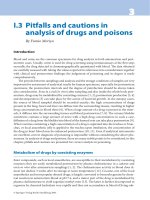
FIGURE 15.5 Instruments for hollow cylinder site preparation.
FIGURE 15.6 Titanium-plasma-sprayed surface (TPS) in a close-up view.
FIGURE 15.7 Micrograph demonstrating direct bone-to-implant con-
tact (osseointegration) to TPS surface (experimental sample from
primate).
15. The ITI Dental Implant System 141
higher magnification reveals the direct apposition of newly
formed bone onto the surface of titanium implants with a TPS
surface without an intervening layer of connective tissue. The
vitality of the bone is demonstrated by the presence of os-
teocytes and blood vessels close to the implant surface (Fig-
ure 15.8). Osseointegration was also confirmed on a few hu-
man implants, which had to be removed (e.g., due to recurrent
peri-implant infections in the crestal area; see Figure 15.9).
Furthermore, direct bone-implant contact was also demon-
strated in scanning electron-microscopic analyses, as well as
in a transmission electron-microscopic study by Listgarten et
al.
17
using titanium evaporated epoxy resin implants (Figure
15.10). Osseointegration is generally not observed to have
100% bone contact along a given implant surface. The extent
of bone-implant interface depends mainly on three factors: (1)
the implant and surface material used; (2) the roughness of
the implant surface; and (3) the density of the surrounding
bone.
As mentioned earlier, ITI implants have been coated with a
TPS surface since their inception in 1974 as this porous tita-
nium surface offers several advantages from a clinical point
of view. An animal study in rats demonstrates that the TPS
surface accelerates bone apposition during early wound heal-
ing.
18
TPS implants revealed the first visible bone-implant
contact after 7 days of healing, whereas smooth titanium im-
plants demonstrated the first contacts after 21 days. In a study
of miniature pigs, titanium implants with TPS coatings demon-
FIGURE 15.9 Osseointegration in apical section of hollow-cylinder
implant, cross-sectional view (human explant).
FIGURE 15.10 Direct bone apposition to TPS surface in electron mi-
croscopic view (magnification 16,000, sample from canine experi-
ment with TPS coated epoxy implants).
FIGURE 15.8 Direct bone-implant contact without interpositioning of
soft tissue. Blood vessels in contact with implant surface (experi-
mental sample from canine model).
142 H P. Weber, D.A. Buser, and D. Weingart
strated a significantly higher percentage of direct bone-implant
contact in cancellous bone when compared to smooth- or fine-
structured titanium surfaces.
19
And finally, a study in sheep
revealed significantly higher removal torques for TPS implants
when compared with smooth- or fine-structured titanium im-
plants.
20
Summarizing these studies, it can be concluded that
titanium implants with TPS surfaces achieve significantly
faster and better bone anchorage when compared with titanium
implants with smooth- or fine-structured surfaces.
To achieve osseointegration of ITI implants, four prereq-
uisites need to be fulfilled: (1) biocompatible material; (2)
atraumatic surgical technique using a slow drilling technique
to prevent overheating of the bone; (3) primary implant sta-
bility; and (4) a healing period of 3 to 4 months without di-
rect loading.
7
As already mentioned, ITI implants were de-
signed as nonsubmerged implants. If placed as such, they
are not covered by the oral mucosa during healing and pen-
etrate the crestal mucosa from the time of implant place-
ment. In contrast to the frequently stated requirement for a
submerged implant placement,
15
nonsubmerged ITI im-
plants achieve osseointegration with high predictability if
the aforementioned prerequisites are followed.
7,21–25
This
clinical fact observed over more than 20 years has been con-
firmed in the recent past by several experimental stud-
ies.
13,14,16,17,19,26–30
Supracrestal Connective Tissue
and Epithelium
Dental implants are not covered by a closed integument. The
fact that they penetrate the mucosa and are consequently ex-
posed to the environment of the oral cavity with all its pos-
sible contaminants creates a delicate problem. Thus the
components of the soft tissue cover (i.e., the supracrestal con-
nective tissue as well as the epithelium) have to act as an im-
portant barrier between the internal and external environment
if long-term function is to be expected.
26
As demonstrated above, bone as mineralized connective tis-
sue adheres to the rough TPS surface. Therefore, it could be
expected that a similar reaction would occur when the non-
mineralized supracrestal connective tissue directly contacted
the TPS surface, and when the implant post is located in ker-
atinized attached mucosa. Light-microscopic experiments on
TPS-coated implants placed in monkeys
16
or beagle dogs
28
demonstrated a fiber orientation perpendicular to the implant
surface (Figure 15.11). However, studies in beagle dogs eval-
uating titanium implants with smooth or sandblasted sur-
faces
17,29
revealed no evidence of perpendicular fiber attach-
FIGURE 15.11 Supracrestal connective tissue fibers in perpendicular
orientation to TPS coated implant surface (cross-sectional view).
FIGURE 15.12 Absence of perpendicular fibers close to the implant
surface. Collagen fibers with a parallel orientation distant from the
implant surface. Blood vessel and cell-free zone in contact with im-
plant surface.
15. The ITI Dental Implant System 143
ment to the tested nonporous titanium surfaces. The connec-
tive tissue in direct contact with the implant post was mainly
dominated by circularly oriented collagen fibers. This inner
zone of connective tissue was free of blood vessels and re-
sembled most likely an inflammation-free scar-tissue forma-
tion (Figure 15.12). The obvious difference to the aforemen-
tioned studies with perpendicular fiber attachment can
probably be explained by the difference in the surface char-
acteristics.
Based on biological considerations for successful mainte-
nance of healthy peri-implant soft tissues, ITI implants have
a smoothly machined titanium surface in the transmucosal
section to reduce the risk of plaque accumulation. Thus it has
to be expected that a similar arrangement of circularly ori-
ented connective tissue fibers is predominantly present around
ITI implants in patients due to the smooth surface in the
supracrestal area (Figure 15.13).
Different light-microscopic studies using nonsubmerged ti-
tanium implants in different animal models
16,28–30
demon-
strated no evidence of an epithelial downgrowth to the bone-
crest level. The micrographs revealed the formation of a
peri-implant sulcus, with the most apical epithelial cells be-
ing located approximately 1 mm above the bone-crest level
(Figure 15.14). The epithelial structures around titanium im-
plants are similar to those found around teeth (i.e., sulcular
epithelium-like and, more apically, junctional epithelium-like
cell layers along the implant surface; see Figure 15.15).
Prosthodontic Concept
Abutments
Various abutments are available for the two-part ITI implants.
They consist of a number of conical abutments for screw-
retained and/or cemented restorations including an angled
abutment (Figure 15.16), an octagonal abutment for screw-
retained restorations only, and the retentive anchor used for
implant treatments with overdentures. The abutments all have
the same apical portion fitting to the inner top portion of the
implant with an M2 (2-mm) screw and an 8° cone (Figure
15.17). This cone-to-screw interface serves as a nonrotational
friction fit or mechanical lock on the basis of the Morse ta-
per principle. It has shown to be three to four times as strong
as a conventional, flat-coupling screw connection.
31
To se-
cure the abutments into this nonrotational fit, they are inserted
with a torque of 35 Ncm using a special torque instrument
(Figure 15.18).
FIGURE 15.13 Circular fibers around implant post in cross-sectional
view (canine experiment).
FIGURE 15.14 Microradiograph demonstrating peri-implant soft tis-
sue morphology. At the top apical extension of peri-implant epithe-
lium. At the bottom is the crestal bone height. Connective tissue con-
tact height extends from the crestal bone height to the epithelium.
F
IGURE 15.19 Solid conical abutments (4-mm, 5.5-mm, and 7-mm
height) for cemented restorations.
144 H P. Weber, D.A. Buser, and D. Weingart
FIGURE 15.15 Peri-implant epithelium resembling sulcular and junc-
tional epithelium at natural teeth.
FIGURE 15.16 ITI abutments. From left to right: Solid abutments,
angled abutment retentive anchor, and octa-abutment.
FIGURE 15.17 Cone-to-screw design (Morse taper principle) for ro-
tation safe anchorage of abutment in implant.
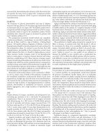
FIGURE 15.18 Torque instrument for abutment insertion (35 Ncm)
and tightening of occlusal screws (20 Ncm).
FIGURE 15.20 Schematic overview of restorative steps for cemented
restorations.
15. The ITI Dental Implant System 145
Conical Abutments
The conical abutments come as solid abutments without in-
ternal screw threads in heights of 4, 5.5, and 7 mm, for ce-
mentation of restorations (Figure 15.19). They are especially
easy to use and, therefore, save time and reduce costs. After
placement of the conical abutment, an impression is made, a
stone cast is poured, and the crowns or fixed partial dentures
are waxed directly to the stone model and then completed as
conventional crown-bridge work (Figure 15.20).
Octa-abutment for Screw-Retained Restorations
For screw-retained prostheses, the Octa-system with different
prefabricated parts for accurate transfer and laboratory proce-
dures has been added to the ITI armamentarium in the more
recent past.
31
The top of the Octa-abutment has eight sides and
is 1.5 mm high (Figure 15.21), with an M2 screw hole in its
top to retain the restoration. This 2-mm occlusal screw limits
the occurrences of screw loosening or fractures commonly re-
ported for implant restorations. The Octa-abutment is anchored
in the implant with the same cone-to-screw interface as the con-
ical abutments described earlier, and they provide a nonrota-
tional friction fit. Transfer copings are used for impressions.
Once an impression is made, one-piece analogs are secured into
the transfer copings and die stone poured. After the stone has
set, the transfer copings are removed. Prefabricated gold cop-
ings made from nonoxidizing, high gold-content alloys with a
high melting range are placed on the analogs. Long wax-up or
guide screws are used to secure the copings on the analogs and
to create the space for the future occlusal screw access canal.
The frame of the future restoration is then waxed and cast to
the copings. In case of porcelain-fused-to-gold restorations, the
porcelain is added thereafter. It is important that for such
restorations, a layer of gold compatible with the ceramic ma-
terial to be used is cast onto the copings. Gold copings with an
octagonal inside are chosen for single-tooth cases, whereas gold
copings with rounded insides are used for fixed partial dentures.
The step-by-step procedure for screw-retained restorations is
summarized in Figure 15.22a,b. The prefabricated gold copings
have an outstanding precision, which can be documented in
SEM images (Figure 15.23). The resistance of the implant-
abutment-superstructure complex to lateral forces is superior
due to the precise component fit and even enhanced by the 45°
inclination of the implant shoulder. Angled abutments and a
transversal screw retention concept have been added to the
prosthodontic concept more recently. For instructions on their
use, the reader is referred to the respective, detailed system lit-
erature. They assist the restorative dentist in overcoming im-
FIGURE 15.22 (a,b) Schematic overview of procedural steps for
screw-retained restorations with the octa-abutment concept and its
prefabricated components.
a
b
Cemented Restorative Technique
FIGURE 15.21 Octa-abutment for screw-retained restoration in close-
up view.
Non-Repositionable
Transfer Technique
146 H P. Weber, D.A. Buser, and D. Weingart
FIGURE 15.23 Precise fit of gold coping to 45° implant shoulder.
FIGURE 15.24 Angled abutments to correct angulation problems in
fixed partial denture cases.
FIGURE 15.25 Transverse screw coping for single-tooth restorations.
F
IGURE 15.26 Octa-abutments on four implants for bar-retained over-
denture.
plant angulation and/or divergence problems (Figures 15.24
and 15.25).
Overdentures on Bars
In cases in which support for dentures is needed, two to four
implants can be placed and restored with a gold bar and an
overdenture after completion of implant healing.
9,10
Prefabri-
cated gold copings, gold bars with round or oval profile, and
gold clips or bar sleeves are the available components. Note
that these gold copings are different from the ones used for
cast restorations. The bar-retaining copings are only to be used
to affix prefabricated bar segments via soldering procedure, in
that they are fit tightly onto the bars and fitted into the denture
as retentive elements (Figures 15.26–15.28).
Overdenture on Retentive Anchors
When moderate additional retention is required for a mandibu-
lar or maxillary denture, two implants can be placed, and
round (retentive) anchors are inserted in the implants after the
3- to 4-month healing period.
32
Because no reopening surgery
is necessary, the restorative phase begins at the end of this
healing period. Female matrices are processed into the den-
ture to fit tightly to the retentive anchors with a simple im-
pression and pick-up method (Figures 15.29–15.31).
Case Reports
Figures 15.32 to 15.37 show illustrative examples from case
reports.
15. The ITI Dental Implant System 147
FIGURE 15.27 Gold bar in place. Bar segments are soldered to gold
copings different from the ones used for cast restorations.
FIGURE 15.28 Finished overdenture demonstrating bar clips in situ.
A metal lingual plate for strength and minimizing interference with
tongue function is recommended as shown.
FIGURE 15.29 Retentive anchor in close-up view.
FIGURE 15.30 Schematic illustration of function of gold matrix on
retentive anchor. The presence of the polyethylene sleeve around the
matrix is important for proper retentive function of the matrix.
FIGURE 15.31 Tissue side of overdenture with retentive matrices in
place.
148 H P. Weber, D.A. Buser, and D. Weingart
FIGURE 15.32 (a) Master cast with dies of conical abutments for ce-
mented crowns. (b) Finished restorations on dies. (c) Lingual view of
cemented restorations. (d) Buccal view of cemented resotrations.
(e) Radiographic control 3 years after implant placement.
a b
c d
e
15. The ITI Dental Implant System 149
FIGURE 15.33 (a) Custom-angled abutment in case with maxil-
lary alveolar protrusion in right canine area. Note the placement
of the implant below tissue level for aesthetic crown emergence.
(b) View of custom angled abutment on an HS implant. The cus-
tom angled abutment was waxed and cast on an octogonal gold
coping and then custom milled. (c) Procelain-fused-to-metal
crown in place. (d) Radiographic control at 3 years after crown
insertion.
a b
c d
150 H P. Weber, D.A. Buser, and D. Weingart
FIGURE 15.34 (a) Octa-abutment placed for screw-retained restoration
in area of the right canine. Note again the deeper implant placement
for aesthetic purposes. (b) Final restoration in place. (c) Radiographic
control 2 years after insertion.
b
c
a
15. The ITI Dental Implant System 151
FIGURE 15.35 (a) Crown post inserted in octa-abutment for fixation of crown via trans-
versal screw in area of missing upper left central incisor. (b) Close-up view of crown
post and SCS screwdriver. (c) Fixation of crown with transversal screw. (d) Aesthetic
appearance of completed tooth replacement. (e) Radiographic control 2 years after
crown insertion.
a b
c d
e
152 H P. Weber, D.A. Buser, and D. Weingart
FIGURE 15.36 (a) Octa-abutments on four implants placed in maxil-
lary edentulous patient. (b) High-profile milled bar in situ. (c) Palate-
free overdenture with bilateral custom fabricated locks which can be
easily opened and closed by the patient. (d) Close-up view of one
of the locks. (e) Frontal view of final prosthesis. (f) Radiographic
control at 1 year.
a b
c d
e
f
15. The ITI Dental Implant System 153
FIGURE 15.37 (a) Retentive anchors in place. (b) Radiographic control at 4 years. (c) Retentive anchor matrices processed in lower over-
denture. (d) Frontal view of final prostheses (i.e., lower overdenture, upper complete denture).
a b
c d
References
1. Sutter F, Schroeder A, Straumann F. ITI Hohlzylinder Systeme.
Prinzipien Methodik Swiss Dent. 1983;4:21.
2. Babbush CA, Kent JN, Misiek DJ. Titanium plasma-sprayed
(TPS) screw implants for the reconstruction of the edentulous
mandible. J Oral Maxillofac Surg. 1986;44:274.
3. Sutter F, Schroeder A, Buser D. The new concept of ITI hol-
low cylinder and hollow screw implants. Part I: Engineering and
design. Int J Oral Maxillofac Implants. 1988;3:161.
4. Buser D, Schroeder A, Sutter F, Lang NP. The new concept of
ITI hollow-cylinder and hollow-screw implants: Part 2, Clinical
aspects, indications, and early clinical results. Int J Oral Max-
illofac Implants. 1988;3:173.
5. Sutter F, Schroeder A, Buser D. Das neue ITI-Implantatkonzept.
Technische Aspekte und Methodik. Quintessenz. 1988;39: (Teil
1)1875–XX; (Teil 2)2057.
6. Sutter F, Krekeler G, Schwammberger AE, Sutter FJ. Das ITI-
Bonefitimplantatsystem: Implantatbettgestaltung. Quintessenz.
1991;42:541.
7. Buser D, Weber HP, Brägger U. The treatment of partially en-
dentulous patients with ITI hollow-screw implants: Pre-surgical
evaluation and surgical procedures. Int J Oral Maxillofac Im-
plants. 1990;5:165.
8. Sutter F. Raveh J. Titanium-coated hollow screw and reconstruc-
tion plate system for bridging of lower jaw defects: Biomechani-
cal aspects. Int J Oral Maxillofac Surg. 1988;17:267.
9. Schroeder A, Maeglin B, Sutter F. Das ITI-Hohlzylinderim-
plantat Typ-F zur Prothesenretention beim zahnlosen Kiefer.
Scheiz Monatsschr Zahnheilk. 1983;93:720.
10. ten Bruggenkate CM, Muller K, Oosterbeek HS. Clinical eval-
uation of the ITI (F-type) hollow cylinder implant. Oral Surg
Oral Med Oral Pathol. 1990;70:693.
11. Hahn H, Palich W. Preliminary evaluation of porous metal sur-
faced titanium for orthopedic implants. J Biomed Mater Res.
1970;4:571.
12. Steinemann S. The properties of titanium. In: Schroeder A, Sut-
ter F, Krekeler G, eds. Oral Implantology: Basics-ITI Hollow
Cylinder. New York: Thieme Medical Publishers; 1991:37–58.
13. Schroeder A, Pohler O, Sutter F. Gewebsreaktion auf ein Titan-
Hohlzylinderimplantat mit Titan-Spritzschichtoberfläche. Schweiz
Monatsschr Zahnheilk. 1976;86:713.
14. Schroeder A, Stich H, Straumann F, Sutter F. Über die An-
lagerung von Osteozement an einen belasteten Implantatkörper.
Schweiz Monatsschr Zahnheilk. 1978;88:1051.
15. Brånemark PI, Hansson BO, Adell R, et al. Osseointegrated im-
plants in the treatment of the edentulous jaw. Experience from a
10-year period. Scand J Plast Reconstruct Surg II. (suppl 16), 1977.
25. Mericske-Stern R, Steinlin-Schaffner T, Marti P, Geering AH.
Peri-implant mucosal aspects of ITI implants supporting over-
dentures. A five-year longitudinal study. Clin Oral Implants Res.
1994;5:9–18.
26. McKinney R, Steflik DE, Koth DL. Per, peri, or trans? A con-
cept from improved dental terminology. J Prosthet Dent. 1984;
52:267.
27. Gotfredsen K, Rostrup E, Hjøerting-Hansen E, Stoltze K, Budtz-
Jørgensen E. Histological and histomorphometrical evaluation
of tissue reactions to endosteal implants in monkeys. Clin Oral
Implants Res. 1991;2:30.
28. Buser D, Stich H, Krekeler G, Schroeder A. Faserstrukturen der
periimplantären Mukosa bei Titan-Implantaten. Eine tierexper-
imentelle Studie am Beagle-Hund Z Zahnärztl Implantol. 1989;
5:15.
29, Buser D, Weber HP, Donath K, et al. Soft tissue reactions to
non-submerged unloaded titanium implants in beagle dogs.
J Periodontol. 1992;63:225.
30. Weber HP, Buser D, Donath K, Fiorellini JP, Doppalapudi V,
Paquette DW, et al. Comparison of healed tissues adjacent to
submerged and non-submerged unloaded titanium dental im-
plants. A histologic and histometric study in beagle dogs. Clin
Oral Implants Res. 1996;7:11.
31. Sutter F, Weber HP, Sorensen J, Belser U. The new restorative
concept of the ITI Dental Implant System: engineering and de-
sign. Int J Periodont Rest Dent. 1993;13:408.
32. Mericske-Stern R, Geering AH. Implantate in der Totalprothetik:
Die Verankerung der Totalprothese im zahnlosen Unterkiefer
durch zwei Implantate mit Einzelattachment. Schweiz Monatss-
chr Zahnmed. 1988;98:871.
154 H P. Weber, D.A. Buser, and D. Weingart
16. Schroeder A, van der Zypen E, Stich H, Sutter F. The reactions
of bone, connective tissue and epithelium to endosteal implants
with titanium-sprayed surfaces. J Maxillofac Surg. 1981;9:15.
17. Listgarten MA, Buser D, Steinemann S, Donath K, Lang NP, We-
ber HP. Light and transmission electron microscopy of the intact
interface between bone, gingiva and non-submerged titanium-
coated epoxy resin implants. J. Dent Res. 1992;71:364–371.
18. Kirsch A, Donath K. Tierexperimentelle Untersuchungen zur
Bedeutung der Mikromorphologie von Titanimplantatober-
flächen. Fortschr Zahnärztl Implantol. 1984;1:35.
19. Buser D, Schenk RK, Steinemann S, Fiorellini JP, Fox C, Stich
H. Influence of surface characteristics on bone reactions to ti-
tanium implants: a histomorphometric study in miniature pigs.
J Biomed Mater Res. 1991;25:889.
20. Wilke HJ, Claes L, Steinemann S. The influence of various ti-
tanium surfaces on the interface shear strength between implants
and bone. Adv Biomater. 1990;9:309.
21. Buser D, Weber HP, Lang NP. Tissue integration of non-sub-
merged implants. Clin Oral Implants Res. 1990;1:33.
22. Buser D, Weber HP, Brägger U, Balsiger C. Tissue integration
of one-stage ITI implants: 3-year results of a longitudinal study
with hollow-cylinder and hollow-screw implants. Int J Oral
Maxillofac Implants. 1991;6:405.
23. Buser D, Sutter F, Weber HP, Belser U, Schroeder A. The ITI
Dental Implant System: basics, indications, clinical procedures
and results. Clark’s Clin Dentistry. 1992;5:1–22.
24. Mericske-Stern R. Clinical evaluation of overdenture restora-
tions supported by osseointegrated implants: a retrospective
study. Int J Oral Maxillofac Implants. 1990;5:375.
16
Localized Ridge Augmentation Using Guided
Bone Regeneration in Deficient Implant Sites
Daniel A. Buser, Dieter Weingart, and Hans-Peter Weber
The use of osseointegrated implants anchored in the jawbone
with direct bone-implant contact has become an increasingly
important treatment modality for the replacement of missing
teeth.
1,2
To expect a predictable long-term prognosis for os-
seointegrated implants, a sufficient volume of healthy bone
should be available at possible recipient sites. Thus a careful
presurgical evaluation is essential to obtain the necessary in-
formation about the quality of the bone, the vertical bone
height, and the orofacial bone width. When this analysis re-
veals that the width of the alveolar ridge is insufficient at de-
sired implant locations, reconstructive surgery is needed if en-
dosseous implants are to be used. One augmentation technique
is based on the principle of guided tissue regeneration using
barrier membranes, which was initially developed for peri-
odontal regeneration.
3,4
A comprehensive text on guided bone
regeneration in implant dentistry has been published by Buser
et al.
5
This principle has been tested for the regeneration of bone
tissue in different types of bone defects as well as around den-
tal implants.
4–23
These studies have in common that barrier
membranes were placed over bone defects and closely adapted
to the surrounding bone surface, creating a secluded space be-
tween the bone and the membrane. With the placement of a
barrier membrane, preference is given to bone-forming cells
that originate from adjacent bone to populate and regenerate
these defects with bone, since competing soft tissue cells from
the mucosa are excluded from these defects. Control sites
without membranes demonstrate incomplete bone regenera-
tion and the presence of soft tissue within the defects. For the
regeneration of bone defects using barrier membranes, the
term guided bone regeneration (GBR) is preferable since this
term describes the purpose of the membrane application more
precisely than does the term guided tissue regeneration (GTR).
In combination with the placement of endosseous implants,
two different applications of GBR are possible: (1) the si-
multaneous approach using membranes to regenerate bone de-
fects around an inserted implant; and (2) the staged approach
using membranes for localized ridge augmentation and place-
ment of implants 6 months later into the newly regenerated
alveolar ridge in a separate surgical procedure.
The clinical testing of GBR in patients for implant indica-
tions started at the University of Bern in 1988, and the poten-
tial of both treatment options was demonstrated.
11,12
From these
early experiences it could be concluded that the biological prin-
ciple of GBR for ridge enlargement is predictable. However,
factors such as soft tissue management, placement of mem-
branes with the provision of sufficient space for bone regener-
ation, primary flap closure, and postsurgical infection control
influence the prognosis to a great degree and must be optimized.
Consequently, the surgical procedures were refined and
technical modifications developed to improve the predict-
ability of the GBR technique.
21–23
In implant patients with an insufficient bone volume, the
surgical approach to be chosen depends on three selection cri-
teria. If the intrasurgical status demonstrates: (1) an implant
cannot be inserted with primary stability; (2) an implant can-
not be inserted in an appropriate position from a prosthetic
point of view; or (3) the peri-implant bone defect would be
relatively extended, the simultaneous application of a barrier
membrane, and an implant would have certain risks. There-
fore, the staged approach is preferred in these situations since
it reduces the risk for compromise or failure of the result.
The goal of the staged approach is a localized ridge aug-
mentation and subsequent placement of endosseous implants
into the newly formed alveolar ridge after a healing period of
6 months.
Based on current experimental and clinical knowledge, a
healthy individual with normal healing capacity and an alveo-
lar bone (defect) site rendering the opportunity for vasculariza-
tion and colonization with bone-forming cells is a good candi-
date for GBR procedure. Additionally, the following clinical
and/or technical prerequisites need to be fulfilled for predictable
success with ridge augmentation procedures.
Appropriate Barrier Membrane
An appropriate membrane to serve as a barrier is necessary.
The mostly used e-PTFE (Teflon) membrane (GTAM, W.L.
Gore and Associates, Flagstaff, AZ) is a nondegradable mem-
155
brane. The structure of this membrane does not allow the
penetration of cells through the membrane, which is an im-
portant factor for its success as a physical barrier. Numer-
ous experimental studies in animals have demonstrated that
this membrane material is bioinert and allows complication-
free tissue integration, provided that submerged healing
without direct contact to the oral cavity can be achieved
(for review, see Buser et al.
5
). Biodegradable membranes
have also been tested in animals and humans with success-
ful outcomes for periodontal indications.
24–28
In these in-
dications, the use of biodegradable membranes gains from
the advantage of avoiding a second surgical procedure for
membrane removal. However, the advantage of using
biodegradable membranes for implant indications is not
considerable since most surgical sites have to be reopened
anyway, either for abutment connection (simultaneous ap-
proach) or for implant placement (staged approach).
Biodegradable membranes may have an advantage over
nondegradable, bioinert membranes for implant indications,
with further research needed for outcomes.
Primary Soft Tissue Healing
It has been clearly demonstrated in clinical applications and
confirmed in experimental studies (for review, see Buser et
al.
5
) that a closed healing of the regeneration site is a pre-
requisite for a predictable result. When a soft tissue dehis-
cence occurs, the exposure of the membrane leads to its
contamination with bacteria from the oral cavity and fre-
quently to an infection in the membrane site within 2 to 3
months, when the membrane remains in place. Since in-
fected membranes cited have an increased risk for a com-
promised surgical result, early membrane removal is gen-
erally recommended in cases of soft tissue dehiscences.
23
Therefore, an appropriate flap design has to be chosen for
predictable achievement of primary soft tissue healing.
Placement of a barrier membrane changes the conditions
for the healing of a soft tissue wound. In the presence of a
barrier membrane, the soft tissue flap is separated from the
bone. As a consequence, the primary soft tissue healing de-
pends mainly on a sufficient vascular supply of the soft-
tissue flaps, and the soft tissue wound cannot be supported
by granulation tissue derived from the underlying bone.
Clinical experience has demonstrated that crestal incisions
do not allow the predictable achievement of primary soft-
tissue healing. The modified incision technique using a lat-
eral incision on the palatal aspect with a combined split-
thickness and full-thickness flap design clearly reduced the
frequency of postoperative soft tissue complications. Other
important factors for primary soft tissue healing are care-
ful handling of the soft tissue flap using fine surgical in-
struments and retraction sutures during surgery as well as
tension-free wound closure with appropriate mattress and
interrupted sutures. Furthermore, a perioperative medica-
tion with nonsteroidal anti-inflammatory drugs and the lo-
cal extraoral application of cold packs in the surgical area
are useful to reduce postoperative swelling.
Membrane Adaptation and Fixation
to Surrounding Bone
Close adaptation is necessary to achieve a sealing effect to
prevent the ingrowth of soft tissue cells derived from the gin-
gival connective tissue because these cells are able to com-
pete with bone-forming cells in the created space underneath
the membrane. In addition, stabilization of the membrane is
useful for maintaining close adaptation of the membrane to
the bone during wound closure. Clinical applications with the
specially designed mini-screws (Memfix System, Institut
Straumann AG, Waldenburg, Switzerland)
21–23
or pins
29,30
have documented their effectiveness for membrane adapta-
tion and stabilization.
Creation and Maintenance of
Secluded Space
A membrane-protected space allows the ingrowth of angio-
genic and osteogenic cells so that bone regeneration is undis-
turbed by competing nonosteogenic soft tissue cells.
14
It is
important to differentiate between space-making defects, such
as an extraction socket with intact bone walls, and non–space-
making defects. Non–space-making defects, including sites
for localized ridge augmentation, are more demanding be-
cause the membrane is not supported by local bone walls. In
these defects, standard e-PTFE membranes are susceptible to
partial collapse caused by the soft tissue cover during heal-
ing.
14,23
Therefore, membrane support for space maintenance
is important.
Attempts have been made to solve this clinical problem in
recent years. One possible solution is the use of stiffer mem-
branes (i.e., reinforced e-PTFE membranes with titanium
mesh) as recommended for periodontal indications.
31
How-
ever, clinical testing must demonstrate if stiffer membranes
also have value for ridge augmentation procedures. Mem-
brane-supporting devices such as mini-screws
21–23
or pins
29,30
have been used. The surgical results were improved, but par-
tial membrane collapse lateral to the support posts still posed
a problem. It became obvious that an appropriate filling ma-
terial was needed in non–space-making defects. Autogenous
bone is still considered the material of first choice for bone
defect grafting.
32,33
Consequently, autografts were used to
156 D.A. Buser, D. Weingart, and H P. Weber
further optimize the ridge augmentation procedure. It was ex-
pected that the combination of autogenous bone grafts and e-
PTFE augmentation material would improve the outcome of
ridge augmentation procedures because the autograft would
not only serve as a membrane-supporting device to maintain
the created space but also act as an osteoconductive scaffold
to accelerate bone regeneration.
It is important to understand the biological behavior of au-
tografts with respect to graft incorporation and repair and the
differences between cortical and cancellous autografts. These
details have been intensively studied in numerous experi-
mental studies in orthopedic surgery (for review, see Bur-
chardt
32,33
). Cancellous autografts are rapidly revascularized,
and they are completely repaired by creeping substitution. In
contrast, revascularization of cortical autografts is slow and
occurs through existing haversian canals. Remodeling of cor-
tical autografts is also slow and results in a mixture of necrotic
and new viable bone.
Based on this biological knowledge of graft incorporation
and graft repair, corticocancellous block grafts placed in the
center of the augmentation area and combined with smaller
bone particles surrounding the block graft were subsequently
used. This surgical approach is based on two assumptions.
First, the cortical portion of the graft facing to the buccal as-
pect of the crest is used to reestablish the missing buccal cor-
tex. Although this new cortex will be a mixture of necrotic
and new viable bone, it offers good mechanical stability and
is less susceptible to resorption than cancellous bone. Second,
the cancellous portion of the graft is placed in direct contact
to the host bone in the area where the implant will be placed
during second surgery. The host bone surface is perforated
during the surgical procedure to activate bone formation and
to open the marrow space, allowing fast ingrowth of blood
vessels. It can be expected that this portion of the graft will
undergo rapid revascularization and graft remodeling. In ad-
dition, the preparation of an implant bed during second
surgery will further activate bone remodeling in this area.
These assumptions, however, are based on orthopedic litera-
ture, and histologic details of graft incorporation and repair
underneath barrier membranes are not yet documented. Ex-
perimental studies evaluating these aspects are currently in
progress.
Corticocancellous block grafts can be harvested either in
the retromolar area of the mandible or in the chin, where the
cortical layer normally has an appropriate thickness of 2 to 3
mm. The harvesting is uncomplicated and feasible within the
extension of the same surgical flap. The block graft should
be appropriately applied to the recipient site. First, rigid fix-
ation of the graft is important. A bone-graft fixation screw
should be used because it allows precise positioning of the
graft and prevents micromovements of the graft underneath
the membrane during healing. Second, the block graft must
be placed with its cortical layer facing buccally and the can-
16. Localized Ridge Augmentation 157
cellous portion of the graft in direct contact of the host bone,
as discussed previously. Based on more than 6 years of ex-
perience with the combination of 3-PTFE membranes and au-
tografts, treatment outcome can clearly be optimized in both
maxillary and mandibular sites,
21–23
as demonstrated in the
clinical examples presented at the end of this section. When
autografts and the GBR technique are combined, the mem-
brane has a double function. First, it serves as a physical bar-
rier to protect the created space against nonosteogenic cells
derived from the mucosa. Second, the membrane serves as a
graft preservation device, protecting the autograft from post-
operative resorption. It has been documented that autogenous
bone graft applied in ridge augmentation procedures without
membranes show resorption of up to 50% after 6 months of
healing.
34
Resorption in ridge augmentation cases has not
been observed when bone grafts were protected by a mem-
brane. This clinical observation has been confirmed in pa-
tients undergoing vertical alveolar ridge augmentation utiliz-
ing autografts from the iliac crest.
35
As an alternative to
autografts, mineralized and demineralized freeze-dried bone
allografts have been used as a membrane-supporting device
in ridge augmentation procedures as well,
15, 36–40
and some
of these publications have presented encouraging clinical re-
sults.
37,39,40
Allografts have the advantage that no harvesting
procedure is necessary. However, histologic details of allo-
graft incorporation and their substitution underneath barrier
membranes and adjacent to implants are not sufficiently
known for each material at present and need further investi-
gation to provide information concerning their predictability
for clinical outcomes.
Healing Time
A last factor important for achieving predictable results is
a sufficiently long healing period. It has been demonstrated
that sites of early membrane removal attain less gain in bone
height.
41–43
However, the exact healing period for ridge
augmentation procedures with the GBR technique is not
known at present. A histologic study involving extended
defects in the alveolar ridge in foxhounds revealed almost
complete cortical and cancellous bone repair and an onset
of bone remodeling after 4 months of healing in membrane-
covered defects.
14
These defects are surgically created and
no osteoconductive filler was used. The study confirmed
that bone regeneration and bone maturation is a time-
dependent process, even in an animal known for its rapid
healing. Based on this fact, a healing period of 9 months
has been used during the development of this technique for
ridge augmentation procedures in large bone defects. Clin-
ical experience has proven this length of time to be effica-
cious.
12, 21–23
However, it can be speculated that the heal-
ing period may be shortened when membranes combined
with autogenous bone grafts are used because of the excel-
lent osteoconductive properties of autografts. This expec-
tation has been confirmed in more than 30 cases with a heal-
ing period of 6 months.
Summary
Over the past several years, the ridge augmentation procedure
using e-PTFE membranes and autografts has proven to be an
efficient and predictable surgical technique.
21–23
This tech-
nique uses a staged approach, which has numerous advantages
over a simultaneous approach in large bone defects in the alve-
olar process. First, it provides a larger bone surface available
to contribute to new bone formation, because no implant is in-
serted in the defect area. With a simultaneous approach, the
inserted implant reduces the exposed bone surface and its mar-
row space as a source of angiogenic and osteogenic cells. Sec-
ond, the implant positioning can be optimized from a pros-
thetic point of view because the implant is placed when the
new crest is already reestablished. Following confirmation of
the treatment outcome, this allows a much easier preparation
of the recipient site and a better initial stability for the implant.
Third, the staged approach offers advantages with respect to
158 D.A. Buser, D. Weingart, and H P. Weber
a
b
c
d
FIGURE 16.1 Staged approach of guided bone regeneration. (a)
Schematic overview of staged approach to augment a deficient alve-
olar ridge. Note lateral split-thickness/full-thickness incision and
wound-closing technique. (b) Patient with missing right lateral in-
cisor. Compromised width of alveolar site. (c) Mucoperiosteal flap
elevated; deficient alveolar bone site does not allow placement of
implant. (d) Corticocancellous bone block graft secured with bone
fixation screw. Small autologous bone chips are arranged around
block graft.
bone maturation because new bone formation is activated
twice by the local release of growth factor.
44
The first activa-
tion occurs during membrane surgery, when the cortical layer
is perforated prior to graft placement. The second activation
occurs during implant placement, when the implant recipient
site is prepared in the newly formed alveolar crest. Finally, it
can be assumed that better bone apposition to the titanium sur-
face can be achieved with a staged approach because the
“travel distance” for osteogenic elements to the implant sur-
face is much shorter. Thus the staged approach should be the
treatment of choice for large bone defects in the alveolar
process, whereas the simultaneous approach can be used in
smaller defects. The question of whether bone regenerated us-
ing the barrier technique is “for real” has recently been an-
swered in two dog experiments.
14, 45
These studies have shown
that the newly regenerated bone closely resembled the struc-
ture of preexisting alveolar bone,
14,45
and osseointegration of
unloaded and loaded implants in these regenerated bone sites
occurred identically as for preexisting bone.
45
Case Reports
Figures 16.1 and 16.2 show illustrative examples from case
reports.
16. Localized Ridge Augmentation 159
e
f
g
h
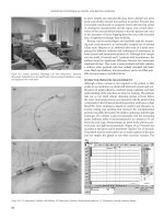
FIGURE 16.1 Continued. (e) GTAM membrane adapted and secured
with miniature fixation screws (Memfix System, Institut Straumann
AG, Waldenburg, Switzerland). (f) Primary flap closure with Gore-
Tex sutures. (g) Postoperative follow-up at 7 months. (h) Reopen-
ing surgery, Memfix screws and membrane removed.
Continued.
160 D.A. Buser, D. Weingart, and H P. Weber
i
j
k
m
l
FIGURE 16.1 Continued. (i) Result of alveolar augmentation in an occlusal view.
Site prepared for ITI Hollow-Cylinder (HC) implant in ideal position. (j) Implant
placed to correct vertical level (i.e., shoulder apical to cementoenamel junction of
neighbor teeth). (k) HC implant in proper axis direction for screw-retained restora-
tion with screw access in the cingulum area of the future crown. (l) Final restora-
tion (porcelain-fused-to-metal) in place. (m) Radiographic control.
16. Localized Ridge Augmentation 161
a
b
c
d
e
f
FIGURE 16.2 Simultaneous approach of guided bone regeneration. (a)
Schematic overview on simultaneous approach for alveolar ridge
augmentation. Note incision technique as in staged approach. (b) Im-
plant placed in area of lower left first molar. Note buccal alveolar
dehiscence. Surrounding bone is perforated with a small round bur
to promote bleeding and a source for cells with bone-forming po-
tential. (c) Autologous bone particles obtained from implant bed
preparation (bone core) placed in area of dehiscence. Small closure
screw placed in implant. (d) GTAM membrane adapted as “poncho”
over implant and secured with two Memfix screws. (e) Primary
wound closure. (f) Postoperative follow-up at 1 month.
Continued.
162 D.A. Buser, D. Weingart, and H P. Weber
References
1. Brånemark P-I, Zarb GA, Albrektsson T, eds. Tissue-Integrated
Prostheses: Osseointegration in Clinical Dentistry. Chicago:
Quintessence; 1985.
2. Schroeder A, Sutter F, Krekeler G, eds. Oral Implantology. Gen-
eral Basics and ITI-Hollow-Cylinder System. New York: Thieme
Medical; 1991.
3. Nyman S, Lindhe J, Karring T. Reattachment-new attachment.
In: Lindhe J, ed. Textbook of Clinical Periodontology. 2nd ed.
Copenhagen: Munksgard; 1989:450–476.
4. Dahlin C, Linde A, Gottlow J, et al. Healing of bone defects by
guided tissue regeneration. Plast Reconstr Surg. 1988;81:
672–676.
5. Buser D, Dahlin C, Schenk RK, eds. Guided Bone Regenera-
tion in Implant Dentistry. Chicago: Quintessence; 1994.
6. Dahlin C, Sennerby L, Lekholm, et al. Generation of new bone
around titanium implants using a membrane technique: An ex-
perimental study in rabbits. Int J Oral Maxillofac Implants.
1989;4:19–25.
7. Dahlin C, Gottlow J, Linde A, et al. Healing of maxillary and
mandibular bone defects using a membrane technique. Scand J
Plast Reconstr Hand Surg. 1990;24:13–19.
8. Seibert J, Nyman S. Localized ridge augmentation in dogs: a pi-
lot study using membranes and hydroxylapatite. J Periodontol.
1990;61;157–165.
9. Becker W, Becker B, Handlesman M, et al. Bone formation at
dehisced dental implant sites treated with implant augmentation
material: a pilot study in dogs. Int J Periodont Rest Dent. 1990;
10:93–101.
10. Lazarra RJ Immediate implant placement into extraction sites:
Surgical and restorative advantages. Int J Periodont Rest Dent.
1989;9:333–343.
11. Nyman S, Lang NP, Buser D, et al. Bone regeneration adjacent
to titanium dental implants using guided tissue regeneration: a
report of two cases. Int J Oral Maxillofac Implants. 1990;5:
9–14.
12. Buser D, Brägger U, Lang NP, et al. Regeneration and en-
largement of jaw bone using guided tissue regeneration. Clin
Oral Implants Res. 1990;1:22–32.
13. Jovanovic S, Spiekermann H, Richter EJ. Bone regeneration
around titanium dental implants in dehisced defect sites: a clin-
ical study. Int J Oral Maxillofac Implants 1992;7:233–241.
14. Schenk RK, Buser D, Hardwick WR, Dahlin C. Healing pattern
of bone regeneration in membrane-protected defects. A histo-
logic study in the canine mandible. Int J Oral Maxillofac Im-
plants. 1994;9:13–29.
15. Gotfredsen K, Warrer K, Hjøerting-Hansen E, et al. Effect of
g
h
i
j
FIGURE 16.2 Continued. (g) Reopening surgery at 6 months. (h) Result of augmentation. Small implant closure screw replaced with trans-
mucosal healing cap. (i) Postoperative follow-up 3 weeks after reopening surgery. (j) Radiographic control 1 year after crown insertion.
membranes and hydroxyapatite on healing in bone defects
around titanium implants. An experimental study in the mon-
key. Clin Oral Implants Res. 1991;2:172–178.
16. Warrer K, Gotfredsen K, Hjøerting-Hansen E, et al. Guided tis-
sue regeneration allowing immediate implantation of dental im-
plants into extraction sockets. An experimental study in the mon-
key. Clin Oral Implants Res. 1991;2:166–171.
17. Wachtel HC, Langford A, Bernimoulin JP, et al. Guided bone
regeneration next to osseointegrated implants in humans. Int J
Oral Maxillofac Implants. 1991;6:127–135.
18. Becker W, Becker B. Guided tissue regeneration for implants
placed into extraction sockets and for implant dehiscences: sur-
gical techniques and case reports. Int J Periodont Rest Dent.
1990;10:377–392.
19. Jovanovic SA, Giovannoli JL. New bone formation by the prin-
ciple of guided tissue regeneration for peri-implant osseous le-
sions. J Parodontol. 1992;11:29–39.
20. Magnusson I, Batich C, Collins BR. New attachment formation
following controlled tissue regeneration using biodegradable
membranes. J Periodontol. 1988;59:1–12.
21. Buser D, Dula K, Belser U, Hirt HP, Berthold H. Localized ridge
augmentation using guided bone regeneration. I. Surgical pro-
cedure in the maxilla. Int J Periodont Rest Dent. 1993;13:29–45.
22. Buser D, Dula K, Belser U, Hirt HP, Berthold H. Localized ridge
augmentation using guided bone regeneration. II. Surgical pro-
cedure in the mandible. Int J Periodont Rest Dent. 1995;15:
13–29.
23. Buser D, Dula K, Hirt HP, Schenk RK. Lateral ridge augmen-
tation using autografts and barrier membranes. A clinical study
in 40 partially edentulous patients. J Oral Maxillofac Surg.
1996;54:420–432.
24. Fleisher N, De Waal H, Bloom A. Regeneration of lost attach-
ment in the dog using Vicryl absorbable mesh (polyglactin 910).
Int J Periodont Rest Dent. 1988;8(2):45–54.
25. Chung KM, Lakin LM, Stein MD, et al. Clinical evaluation of
a biodegradable collagen membrane in guided tissue regenera-
tion. J Periodontol. 1990;61:732–741.
26. Schultz AJ, Gager AH. Guided tissue regeneration using ab-
sorbable membrane (polyglactin 910) and osseous grafting. Int
J Periodont Rest Dent. 1990;10:8–15.
27. Zappa U. Resorbierbare Membranen. I. Parodontale Gewebere-
generation unter Verwendung von resorbierbaren Membranen-
klinische Aspekte. Schweiz Monatsschr Zahnmed. 1991;101:
1147–1155.
28. Zappa U. Resorbierbare Membranen. II. Parodontale Gewe-
beregeneration unter Verwendung von resorbierbaren Membra-
nen—Histologische Aspekte. Schweiz Monatsschr Zahnmed.
1991;101:1321–1331.
29. Fugazzotto P. Ridge augmentation with titanium screws and
guided tissue regeneration: Technique and report of a case. Int
J Periodont Rest Dent. 1993;13:335–339.
30. Becker W, Becker BE, McGuire MK. Localized ridge augmen-
tation using absorbable pins and e-PTFE barrier membranes: a
new surgical technique. Case reports. Int J Periodont Rest Dent.
1994;14:49–61.
31. Tinti C, Vincenzi G, Cochetto R. Guided tissue regeneration in
mucogingival surgery. J Periodontol. 1993;64:1184–1191.
32. Burchardt H. Biology of bone transplantation. Orthodont Clin
North Am. 1987;18:187–196.
33. Burchardt H. Biology of bone graft repair. Clin Orthop Relat
Res. 1983;174:28–42.
34. ten Bruggenkate CM, Kraajenhagen HA, van der Kwast WAM,
et al. Autogenous maxillary bone grafts in conjunction with
placement of ITI endosseous implants. A preliminary report. Int
J Oral Maxillofac Surg. 1992;21:81–84.
35. Jensen O. Guided bone graft augmentation. In: Buser D, Dahlin
C, Schenk RK, eds. Guided Bone Regeneration in Implant Den-
tistry. Chicago: Quintessence; 1994:235–264.
36. Buser D, Berthold H. Knochendefektfüllung im Kieferbereich
mit Kollagenvlies. Dtsch Z Mund Kiefer Gesichtschir. 1986;10:
191–198.
37. Nevins R, Mellonig JT. Enhancement of the damaged edentu-
lous ridge to receive dental implants: A combination of allograft
and the GoreTex membrane. Int J Periodont Rest Dent. 1992;
12:97–111.
38. Becker B, Lynch S, Lekholm U, et al. A comparison of three
methods for promoting bone formation around implants placed
into immediate extraction sockets: e-PTFE membrane alone, or
with either PDGF and IGF-I, or DFDB. J Periodontol. 1992;63:
929–940.
39. Shanaman RH. The use of guided tissue regeneration to facili-
tate ideal prosthetic placement of implants. Int J Periodont Rest
Dent. 1992;12:226–265.
40. Nevins R, Mellonig JT. The advantages of localized ridge aug-
mentation prior to implant placement: a staged event. Int J Pe-
riodont Rest Dent. 1994;14:97–111.
41. Simion M, Baldoni M, Rossi P, Zaffe D. A comparative study
of the effectiveness of e-PTFE membranes with and without
early exposure during the healing period. Int J Periodont Rest
Dent. 1994;14:167–180.
42. Becker W, Dahlin C, Becker BE, et al. The use of e-PTFE bar-
rier membranes for bone promotion around titanium implants
placed into extraction sockets: a prospective multicenter study.
Int J Maxillofac Implants. 1994;9:31–40.
43. Lekholm U, Becker W, Dahlin C, et al. The role of early vs late
removal of GTAM membranes on bone formation around oral
implants placed in immediate extraction sockets: an experi-
mental study in dogs. Clin Oral Implants Res. 1993;4:121–129.
44. Schenk RK. Bone regeneration: biologic basis. In: Buser D,
Dahlin C, Schenk RK, eds. Guided Bone Regeneration in Im-
plant Dentistry. Chicago: Quintessence; 1994:49–100.
45. Buser D, Ruskin J, Higginbottom F, Hardwick R, Dahlin C,
Schenk RK. Osseointegration of titanium implants in bone re-
generated in membrane-protected defects: a histologic study in
the canine mandible. Int J Oral Maxillofac Implants. 1995;10:
666–681.
16. Localized Ridge Augmentation 163
17
The ITI Dental Implant System
in Maxillofacial Applications
Dieter Weingart, Daniel A. Buser, and Hans-Peter Weber
In severe trauma cases, after jaw resection in tumor surgery,
and especially in cases of severe atrophy of the maxillary or
mandibular alveolar ridge, a direct implant placement using
the one-stage approach with ITI implants as described in
Chapter 15 is often not possible. Also, the technique of guided
bone regeneration discussed in that chapter would not be an
efficient method to restore areas of such extended and severe
alveolar atrophy. Therefore, a vertical augmentation with
bone grafts most frequently obtained from the iliac crest is
the method of choice in patients presenting with such condi-
tions (Figures 17.1–17.4). As with guided bone regeneration,
two methods regarding timing of implant placement may be
differentiated: (1) implant insertion simultaneously with the
bone grafts in which instance the implants serve to stabilize
the grafts to the basal bone; and (2) stage approach, that is,
the bone grafts are stabilized by means of miniplates or
screws, which are removed after graft healing at which time
the implants are inserted (Figures 17.1 and 17.2).
As a prerequisite for the use of free bone grafts, a maximum
wound closure during the healing phase is required. Accord-
ingly, the implants in this indication need to be inserted to the
bone level, and the mucoperiosteal flap must cover the implants
after suturing. A modification of the standard ITI Dental Im-
plant System was necessary to allow that at the time of second-
stage surgery (i.e., after bone-graft healing and osseointegra-
tion of the implants) transmucosal extensions can be attached.
For this purpose, the ITI Extender System was developed.
1–5
The available extensions allow the adaptation of the peri-
implant mucosa to this transmucosal component (Figure 17.5d).
After completion of soft tissue healing following second-
stage surgery, any of the prosthetic abutments of the regular
ITI system may be placed on top of the extensions, and the
superstructure is fabricated according to standard procedures.
Surgical Procedure
As outlined earlier, the implants used for the stabilization of
bone grafts are to be inserted into the transplants in a sub-
merged manner, mainly for reasons of infection prophylaxis
and prevention of graft resorption. The ITI full-body screws,
available in lengths of 6 to 16 mm, are used for these indi-
cations. Owing to their flared neck, the ITI screw implants
function as tension screws, building up an interfragmentary
compression between the natural bone bed of the jaw bone
and the bone transplant (Figure 17.6e).
The surgical augmentation procedure and the implantation
with ITI screw implants as well as the use of the transgingi-
val extension system is documented step by step in Figures
17.5 and 17.6. At first surgery, the implant (ITI FS) is inserted
to its shoulder into the bone graft and covered with a small
closure screw. The mucoperiosteal flap is then positioned over
the bone graft and implants (Figure 17.6g). At second-stage
surgery following a healing phase of 3 to 6 months, the im-
plants are exposed, the healing caps removed, and the basal
screws and the mucosa cylinders are inserted and covered with
healing caps (Figures 17.5a–d). After completion of wound
healing (3 to 4 weeks), the prosthetic phase is started with the
insertion of the abutments after removal of the healing caps.
Mechanical Aspects
At second-stage surgery, it is important to consider that the
basal screw and the mucosa cylinder are used in correspond-
ing pairs and in accordance with the standard lengths (Figure
17.7). The microgaps between the implant and the extension
parts are kept as small as technically possible.
This transgingival unit of the extender system has been me-
chanically tested under different loading conditions. As a re-
sult of preliminary tests with different designs, an integrated
attachment (basal screw) was chosen. As usual for ITI sec-
ondary components, its apical portion comprises an 8° cone
and a 2-mm screw for attachment to the implant. This cone-
to-screw design provides a frictional fit, eliminating the risk
of loosening of the basal screw. The design of the coronal
portions of the basal screw consists of a threaded part to which
the corresponding mucosa cylinder is attached (Figure 17.7).
It is preferably tightened with a torque meter adjusted to ap-
proximately 35 Ncm.
164