Chemical Degradation Methods for Wastes and Pollutants - Chapter 3 potx
Bạn đang xem bản rút gọn của tài liệu. Xem và tải ngay bản đầy đủ của tài liệu tại đây (663.16 KB, 43 trang )
3
Supercritical Water Oxidation
Technology
Indira Jayaweera
SRI International, Menlo Park, California, U.S.A.
I. INTRODUCTION
Supercritical water oxidation (SCWO) is a waste treatment technology that
uses supercritical water as a medium for oxidizing organic material. SCWO
can also be described as an extension of the subcritical oxidation process,
wet air oxidation (WAO) process, or widely known Zimpro process [1].*
Both processes (SCWO and WAO) involve bringing together organic waste,
water, and an oxidant (such as air or oxygen) to elevated temperatures and
pressures to bring about chemical oxidations. Generic operational condi-
tions for the two processes are as follows:
WAO: 150–300jC, 10–200 bar
SCWO: > 374–675jC, > 220 bar.
Fig. 1 shows a graphical representation of these operational regions.
WAO and SCWO processes are often referred to as hydrothermal oxida-
tion technologies (HTOs). The major difference between the processes is
that, in SCWO, organics are completely oxidized in a relatively short time
(seconds to minutes), whereas in WAO, the reaction may require a longer
time (minutes to hours). Furthermore, in WAO, some refractory organics
are not completely oxidized because of the lower temperature of operation
* The pioneering work of Fred Zimmerman in the 1950s led to the creation of the Zimpro
process [1].
TM
Copyright © 2003 by Marcel Dekker, Inc. All Rights Reserved.
(<350jC), thus requiring a secondary treatment process. As information on
WAO technology is readily available from other sources [2–5], the SCWO
process is mainly discussed here.
The SCWO process is ideal for the disposal of many aqueous hazardous
materials (e.g., EPA priority pollutants, industrial wastewater and sludges,
municipal sludges, agricultural chemicals, and laboratory wastes), but has
also been demonstrated to effectively destroy military wastes (e.g., ordnance,
rocket propellants, and chemical agents) [6–18]. The effluent from the SCWO
process, consisting primarily of water and carbon dioxide, is relatively benign.
Therefore, the SCWO process can easily be designed as a full-scale contain-
ment process with no release of pollutants to the atmosphere. Compared with
incineration and other high-temperature treatments, such as the plasma
process, SCWO processes achieve high organic destruction efficiencies
(>99.99%) at much lower temperatures (<700jC) and without NO
x
production.
Sanjay Amin, a student of Michael Modell at Massachusetts Institute
of Technology, first discovered in the mid-1970s the effect of supercritical
water for decomposition of organic compounds without forming tar [19].
Figure 1 Phase diagram for pure water. Solid line: liquid–gas equilibrium.
Jayaweera122
TM
Copyright © 2003 by Marcel Dekker, Inc. All Rights Reserved.
This information, together with the information available at the time from
Connolly’s 1966 publication [20], which stated that organics can be solubi-
lized in all proportions in high-temperature pressurized water, has led to the
birth of the SCWO process. The breakthrough of the SCWO process seems
to stem from the work of E. U. Frank, Karlsruhe, Germany, and Marshall
and coworkers, Oak Ridge, TN , on the thermodynamics of binary mixtures
of gases, organics, and inorganics in subcritical and supercritical water [21–23
and references therein]. Although the technology was invented in the late
1970s, much of the development work was conducted from 1980 to the early
1990s. During this period, researchers demonstrated the great utility of SCWO
as a method for waste disposal without production of harmful products.
However, during the same period, the major technical obstacles to
commercialization of the process had also been discovered. The two major
technical challenges were reactor corrosion and reactor plugging. Reactor
corrosion is caused by the formation of acids during the processing,
especially when waste streams containing acid-forming components (e.g.,
chlorinated organics) are treated. Reactor plugging occurs when inorganic
salts present in the waste stream are precipitated during the processing.
Thus, the major criteria for designing the process involve consideration of
possible corrosion and reactor plugging, as most industrial waste streams
contain inorganic solids or heteroatoms that form inorganic solids for a
majority of the SCWO systems. In addition, the problems associated with
salt plugging and corrosion vary with the SCWO operating conditions (or
the type of SCWO system). In general, there are several diff erent versions of
SCWO systems (low- and high-temperature SCWO, moderate and very high
pressure SCWO, catalytic and -noncatalytic SCWO, etc.). Most of these
different SCWO systems have been developed to overcome problems and to
improve the performance of the process. However, only a few of those
SCWO processes are commercially available and commonly practiced
SCWO systems are discussed in this chapter.*
II. BACKGROUND AND FUNDAMENTALS OF SCWO
A. General Description
The SCWO process involves bringing together an aqueous waste stream and
oxygen in a heated pressurized reactor operating above the critical point of
* Only the aboveground SCWO systems are discussed here. There is an underground SCWO
system that uses hydrostatic pressure to avoid the need for high-pressure pumps. This system
was designed by Oxydyne Corporation, Dallas, TX.
Supercritical Water Oxidation Technology 123
TM
Copyright © 2003 by Marcel Dekker, Inc. All Rights Reserved.
water (374jC, 22.1 MPa or 218 atm). Under these co nditions, the solubility
properties of water are reversed (i.e., increased organic solubility and
decreased inorganic solubility*), and the viscosity of the media is decreased
to a value similar to -gaslike values, thus enhancing the mass transfer
properties. These unique properties of hot pressurized water allow oxygen
and organics to be contacted in a single phase in which oxidation of organics
proceed rapidly. At 400–650jC and 3750 psi, SCWO can be used to achieve
complete oxidation of many organic compounds with destruction rate
efficiencies of 99.99% or higher.
A generic flow diagram for the SCWO process is given in Fig. 2. The
aqueous waste is brought to system pressure using one or more high-
pressure pumps. Compressed air or oxygen is added to the pressurized
waste, and the waste–air mixture is initially heated to about 300jC using a
preheater. The preheated mixture is directed to the main reactor operated at
thedesiredtemperature(above374jC), where the complete oxidation
occurs. The effluent from the reactor then travels through a heat exchanger,
a pressure letdown valve, and a solid/liquid/gas separator.
The preheater section of the system mimics a miniature WAO system
because the reaction conditions in the preheater are similar to those of a
WAO system except that WAO systems need longer reaction times. In the
heat-recovery mode of operation, the SCWO uses the heat from the reaction
to preheat the influent. As a rule of thumb, if the aqueous waste stream
contains about 4 wt.% of organics, the SCWO can be processed under self-
sufficient heat conditions. However, for dilute aqueous waste streams, the
SCWO process may not be cost-effective because of the additional thermal
energy required to maintain the reactor temperature in the 400–650jC range.
Figure 2 A generic hydrothermal oxidation (WAO, SCWO) process flow diagram.
* The details of the inorganic solubility are given in Sec. B.2., Phase Separations.
Jayaweera124
TM
Copyright © 2003 by Marcel Dekker, Inc. All Rights Reserved.
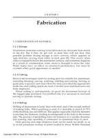
B. In-Depth Treatment of SCWO
1. Fluid Characteristics
The basic properties of water such as viscosity, dissociation constant,
dielectric constant, compressibility, and the coefficient of thermal expansion
play a major role in determining optimal reaction conditions for obtaining
maximum benefits in both SCWO and WAO processes. The properties of
water change dramatically with temperature, particularly near the critical
point [24–26]. A well-known example, the variation of pK
w
with temperature
at the saturation pressure, is shown in Fig. 3. The dissociation constant of
water goes through a maximum around 250jC(pK
w
minimum), and then
undergoes a sharp decline as the temperature approaches the critical point.
The density and the dielectric constant of wat er also show sharp changes close
to the critical point, as shown in Fig. 4.
The rate-limiting properties of any organic reaction that includes the
mixing of several components are the solubility of the contaminant in the
liquid phase or its equilibrium solubility, and the mass transfer step (i.e.,
Figure 3 Variation of pK
w
with temperature at the saturation pressure.
Supercritical Water Oxidation Technology 125
TM
Copyright © 2003 by Marcel Dekker, Inc. All Rights Reserved.
dissolution into the aqueous phase). Therefore, the transport properties of
the reaction media are very important for efficient waste processing. The
viscosity of water decreases with temperature, thus providing rapid diffu-
sion. The conductance of heated water remains high in spite of the decrease
in the dielectric constant because of the increased ion mobility brought
about by the decreased viscosity. However, as the dielectric constant of
water decreases with the increase in temperature, electrolytes that are
completely dissociated at low temperature become much less dissociated
at high temperature, particularly in the supercritical region. At the critical
point (374jC, 218 atm pressure, dielectric constant, e=5), water acts as a
mildly polar organic solvent, and thus supercritical water can readily
solubilize nonpolar organic molecules. In fact, most hydrocarbons become
soluble in water between 200j and 250jC [27], allowing opportunities to
enhance reactivities of organics even under subcritical water conditions. The
enhanced diffusivity and the decreased dielectric constant at elevated
temperatures make water an excellent solvent for dissolving organic materi-
Figure 4 Variation of density and dielectric constant with temperature at the
saturation pressure.
Jayaweera126
TM
Copyright © 2003 by Marcel Dekker, Inc. All Rights Reserved.
als that are tightly bound to solid material (important for treatment of solid
waste). As an example, hot pressurized water has been shown to break and
separate ‘‘highly stable’’ water–oil–solid emulsions, generated in petroleum
wastewater treatment and other industrial operations [28].
Compared with ambient values, the specific heat capacity of water
approaches infinity at the critical point and remains an order of magnitude
higher in the critical region [26], making supercritical water an excellent
thermal energy carrier. As an example, direct measurements of the heat
capacity of dilute solutions of argon in water from room temperature to
300jC have shown that the heat capacities are fairly constant up to about
175–200jC, but begin to increase rapidly at around 225jC and appear to
reach infinity at the critical temperature of water [29].
The static dielectric constant is a measure of hydrogen bonding and
reflects the characteristics of the polar molecules in water. However, very little
is known about the degree of hydrogen bonding under supercritical water
oxidation conditions. The lack of data on the character of hydrogen bonding
in water at high temperatures and pressures hinders the understanding of the
structure and pr operties of supercritical water. The important question is: Up
to what temperature can hydrogen bonding in water exist? It was initially
believed that hydrogen bonds do not exist above 420 K. Later, Murchi and
Eyring [30], using the approach of significant structures, showed that the hy-
drogen bonds disappear above 523 K and that water above this temperature
consists of free monomers. Later, Luck [31], studying the IR absorption in
liquid water, extended the limit of hydrogen bonding at least up to the criti-
cal temperature. Recently, a theoretical model developed by Gupta et al. [32]
has shown that in supercritical water, significant amounts of hydrogen bond-
ing are still present despite all the thermal energy and are highly pressure and
temperature dependent. An interesting result has emerged from Sandia Na-
tional Laboratories’ theoretical estimation of hydrogen bonding of super-
critical media by calculating the equilibrium population of water polymers
(dimers, trimers, etc.) [33]; however, this contradicts the Murch and Eyring
findings above [30]. Their calculations have shown that at 450–650jC and
240–350 bar, the water polymer concentration can be as high as 40%. It is also
cited in later work by Kalinichev and Bass [34] that hydrogen bonding is still
present in the form of dimers and trimers in the supercritical state. More
details and new theoretical discussions can be found in Refs. 35, 36, and the
references therein.
2. Phase Separations
It is important that the phase behavior of the influent at high temperature
and pressure conditions be clearly understood for designing process compo-
Supercritical Water Oxidation Technology 127
TM
Copyright © 2003 by Marcel Dekker, Inc. All Rights Reserved.
nents such as the main reactor. Under the operational conditions of SCWO,
the conditions can be easily adjusted to attain a single phase when only
organics are present. However, when inorganic salts are present (either as a
reagent or as a by-product from the process) under SCWO conditions, it is
challenging or even impossible to predict the phase behavior of the medium.
The presence of electrolytes changes the saturation–vapor boundary
line for water. Liquid–vapor equilibria in a soluble salt–water system above
the critical temperature are complex. However, the situation below the
critical temperature of pure water is simpler, at least for solutes that are so
involatile at this temperature that their concentrations in the vapor phase are
negligible. Liquid solutions of these solutes have vapor pressures that are
lower at a given temperature than that of pure water. Equivalently, they have
boiling points that are higher at a given total pressure than that of pure
water. Fig. 5 shows the relationship between vapor pressure and temperature
for Na
2
CO
3
–H
2
O and NaCl–H
2
O systems [36]. It is clear that these two
systems have different phase behaviors under SCWO conditions. Because of
the complex nature of the phase diagrams for salt-water systems and the
Figure 5 The relationship between vapor pressure and temperature for the
Na
2
CO
3
–H
2
O and NaCl–H
2
O systems.
Jayaweera128
TM
Copyright © 2003 by Marcel Dekker, Inc. All Rights Reserved.
inconsistencies of the available literature data, only a brief discussion is given
below with appropriate references.
In recent years, studies of the phase behavior of salt-water systems
have primarily been carried out by Russian investigators (headed by Prof.
Vladimir Valyashko) at the Kurnakov Institute in Moscow, particularly for
fundamental understanding of the phase behavior of such systems. Val-
yashko [37,39,42,43], Ravich [38], Urosova and Valyashko [40], and Ravich
et al. [41] have given a classification of the existence of two types of salts,
depending on whether the critical behavior is observed in saturated solu-
tions. Type 1 does not exhibit critical behavior in saturated solutions. The
classic example of Type 1 is the NaCl–water system and has been studied by
many authors [36,37,44–47]. The Type 2 systems exhibit critical behaviors in
saturated solutions, and therefore have discontinuous solid–liquid–vapor
equilibria. Table 1 shows the classification of binary mixtures of salt–water
systems.
In brief, the salts that are classified as Type 1 have increasing solubility
with increasing temperature, whereas Type 2 salts show an opposite trend.
For example, sodium carbonate, a Type 2 salt, has a 30 wt.% solubility under
ambient conditions and its solubility near the critical point approaches zero
[36] whereas sodium chloride, a Type 1 salt, has a 37 wt.% solubility under
subcritical conditions at 300jC and about 120 ppm at 550jC [46].
In real systems, organic–inorganic multicomponent phase systems are
possible, and the information gathered from binary or ternary systems
cannot be extended to these real situations. Currently, Valyashko from
Kurnakov Institute and Jayaweera from SRI International are jointly study-
Table 1 Saltwater Binary Systems
Type 1 salts Type 2 salts
KF, RbF, CsF LiF, NaF
LiCl, LiBr, LiI Li
2
CO
3
,Na
2
CO
3
NaCl, NaBr, NaI Li
2
SO
4
,Na
2
SO
4
,K
2
SO
4
K
2
CO
3
, RbCO
3
Li
2
SiO
3
,Na
2
SiO
3
Rb
2
SO
4
Na
3
PO
4
Na
2
SeO
4
CaF
2
, SrF
2
, BAF
2
K
2
SiO
3
SiO
2
,Al
2
O
3
K
3
PO
4
CaCl
2
, CaBr
2
, CaI
2
BaCl
2
, BaBr
2
NaOH, KOH
Source: Ref. 37.
Supercritical Water Oxidation Technology 129
TM
Copyright © 2003 by Marcel Dekker, Inc. All Rights Reserved.
ing both the phase behavior and the morphology changes of salts precipitated
from a salt-water system containing Na
2
CO
3
,K
2
CO
3
, and NaCl [48].
Importance of Electrochemistry in SCWO Processing. In both WAO
and SCWO processing, where the reactor surfaces experience extremes in
pH and high inorganic salt concentrations under high temperature/high
pressure conditions, enhanced electrochemical processes could cause corro-
sion and rapid metallurgical degradations of the reactor vessels. Therefore,
materials should be evaluated to determine if they could withstand the
SCWO conditions. In general, researchers have been mainly focused on
understanding the corrosion processes such as pitting corrosion (disruption
of the protective oxide surface layer followed by the heavily localized
dissolution of the underlying alloy, forming holes or pits), crevice corrosion
(localized form of corrosion associated with stagnant solutions in crevices),
and stress corrosion cracking (cracking induced by the combined influence
of the tensile stress and corrosive medium) under SCWO conditions [49]; a
detailed description of metallurgical aspects, material properties, thermody-
namics of the corrosion process, corrosion kinetics, and corrosion phenom-
ena under hydrothermal conditions can be found in Refs. 51 and 52.
In predicting metal stability under aqueous environments, it is custom-
ary to use electrochemical potential–pH diagrams (E
h
–pH or Pourbaix
diagrams). Many workers have derived and published potential–pH diagrams
for metal–water systems under varying temperature and pressure conditions
[52–54]. Cr, Fe, and Ni systems are the most widely studied systems (the alloys
currently used for WAO and SCWO studies contain Cr, Fe, and Ni, e.g.,
stainless steel 316 and Hast elloy C2-276). Under oxidative conditions, metal
oxide films are formed on the reactor surfaces. Some metal oxides, such as
Fe
3
O
4
,Cr
2
O
3
, etc., will passivate the metal surface reducing the corrosion,
and thus both immunity and passivation regions, where a process can be
operated with minimal corrosion, are possible. In the case of chromium, the
shift in the equilibrium line for the oxidative dissolution of Cr
2
O
3
Cr
2
O
3
þ 5H
2
O ! 2CrO
À
4
þ 10H
þ
þ 8e
À
with increasing temperature is of practical importance for stainless steel,
because it is the formation of chromic oxide (or at least a chromium-
containing spinel, e.g., FeCr
2
O
4
) that confers passivity to the alloy. Research-
ers have tried to evaluate the effect of secondary metals on the primary metal
in alloys by adding corresponding salts to the corrosion medium. For
example, Fig. 6 shows the pos sible passivity, immunity, and corrosion areas
for iron in the presence of CrO
4
2–
under ambient conditions [52].
The potential–pH diagrams under ambient conditions cannot be used
to predict the stability at higher temperatures. The passivation region for
Jayaweera130
TM
Copyright © 2003 by Marcel Dekker, Inc. All Rights Reserved.
iron is different at supercritical conditions compared to ambient conditions.
High-temperature - thermodynamic properties have to be properly incorpo-
rated when evaluating the diagrams for elevated temperatures. However, it
should be noted that accurate determination of potential–pH diagrams is
impossible because of uncertainties about existing equilibria of different
species at elevated temperatures.
It is also important to note that the electrochemical potential of the
system is dependent on the equilibrium between various ions present in the
system and cannot be changed without application of an external potential
(e.g., cathodic protection) or addition of a chemical (e.g., corrosion inhib-
itor). Emphasis should thus be placed on the interpretation of the data
contained within the E
h
–pH diagrams, with particular attention being paid
Figure 6 Potential–pH diagram: the possible passivity, immunity and corrosion
areas for iron in the presence of CrO
4
2À
under ambient conditions.
Supercritical Water Oxidation Technology 131
TM
Copyright © 2003 by Marcel Dekker, Inc. All Rights Reserved.
to the limitations that are imposed by the fact that they are at equilibrium
rather than the kinetic descriptions of a system. One must take precautions
when using potential–pH diagrams for predicting possible corrosion in
metal–water systems. They are used only as a guide, and the experimental
data must be used for accurate prediction of corrosion rate. Further details
can be found in the ‘‘Interference from Reactor Corrosion.’’ section.
III. DEGRADATION OF POLLUTANTS
A. Laboratory-Scale Experimental Design
The laboratory-scale experimental setups are designed typically to conduct
chemical reaction studies under a range of pressures, temperatures, densities,
oxidant and organic concentrations, and residence times in several reactor
configurations. In general, model compounds for simulating common pollu-
tants in industrial waste streams are used in laboratory-scale experiments.
Selection of the reactor to achieve the required reaction time is one of
the key aspects of designing the laboratory-scale experiments.* There are
several types of reactors that can be used for this purpose: small batch reactors
or bombs, tubular plug-flow reactors (PFRs), and stirred tank reactor systems
(STRs) on either batch or continuous mode. Small batch reactor setups are
the most convenient and ideal for initial scouting experiments to determine
general conversion and suitable conditions for continuous flow operation. In
addition, it is convenient when the change in surface-to-volume ratio is
required for studying the surface effects on the reaction rates. Batch reactor
setups are generally small bombs that can easily be custom-made using high-
pressure stainless steel tubing. During testing, these reactors are loaded with
predetermined amounts of water, oxidant, and the organic material , and the
closed reactor is then heated in an isothermal oven. These systems are self-
pressurized, and the reactor pressure can be changed by increasing the water
loading, which in turn increases the density; steam tables provide the relation-
ships between the water loading and the pressure [24,25].
Tubular reactor advantages include their well-defined residence time
distributions, turbulent mixing reactants, ease of obtaining and applying ki-
netic data, efficient use of reactor volume, and mechanical simplicity. How-
ever, great care must be taken when applying the correct flow model (e.g., plug
* It is important to note that most large-scale SCWO reactors are designed to be turbulent flow.
In addition, some of the reactors (e.g., transpiring wall reactor) are not possible to scale down
for laboratory-scale experiments. The method given here is a generic approach for under-
standing the reaction kinetics of pollutants under SCWO conditions.
Jayaweera132
TM
Copyright © 2003 by Marcel Dekker, Inc. All Rights Reserved.
flow assumption) for evaluating reaction times, and numerous limitations
accompany the use of the plug-flow treatment of tubular flow reactor data. A
critical evaluation of the plug-flow idealization for supercritical water oxida-
tion is reported by Cutler et al. [55]. More detailed criteria for evaluating the
legitimacy of plug-flow idealization for general applications are given by
Mulcahy and Pethard [56] and Furue and Pacey [57].
Stirred tank reactors are very useful when the reagents contain multi-
ple components that could exist in separate phases. In addition, it is a
convenient way to achieve long reaction times for the study of slow kinetic
processes. The attainable reaction time depends on the size of the reactor
(e.g., 100 to 2000 mL). Sample schematics of STR and PFR systems are
given in Figs. 7 and 8, respectively.
In designing laboratory-scale experiments, it is important to use proper
analytical methods for determining both organic and inorganic species to
Figure 7 A bench-scale stirred tank reactor system for subcritical and supercritical
studies. (From SRI International.)
Supercritical Water Oxidation Technology 133
TM
Copyright © 2003 by Marcel Dekker, Inc. All Rights Reserved.
examine the kinetics of the oxidation of pollutants, because both species are
present in the treatment of waste. In most cases, where only the destruction
rate efficiency (DRE) is required, it is customary to use either the total or-
ganic content (TOC) or the chemical oxygen demand (COD) as the analytical
parameter. However, when the studies are targeted for detailed understand-
ing of the process, an in-depth analysis on all the phases is required.
Commonly used analytical techniques for analyzing liquid and gas samples
from the treated pollutants include gas chromatography (GC) (with flame
ionization and thermal conductivity detectors), gas chromatography–mass
spectrometry (GC-MS), ion chromatography for analysis of inorganic
anions and cations, and inductively coupled plasma–atomic emission spec-
troscopy (ICP) for metal analysis. During the initial development of SCWO,
Figure 8 A continuous flow reactor system for subcritical and supercritical studies.
(From SRI International.)
Jayaweera134
TM
Copyright © 2003 by Marcel Dekker, Inc. All Rights Reserved.
some researchers have also used in situ optical methods for quantification of
gaseous species in the supercritical media [58,59] (SF Rice, personal com-
munication, 1998). Recently, a hot stage microscope or diamond cell obser-
vation cell has been used to visually observe the supercritical media [61]. Such
visual observation reactors provide insight into the phase behavior of
supercritical fluids containing inorganic salts.
B. Examples
To date, numerous model compounds simulating the pollutants in common
waste streams have been studied under laboratory-scale conditions by many
researchers to determine their reactivities and to understand the reaction
mechanisms under supercritical water oxidation conditions. Among them,
hydrogen, carbon monoxide, methanol, methylene chloride, phenol, and
chlorophenol have been extensively studied, including global rate expressions
with reaction orders and activation energies [58–70] (SF Rice, personal
communication, 1998).
1. Mechanisms
Because the reactions of organic compounds with oxygen are very complex
and because it is not essential to understand the reaction mechanisms for
engineering purposes, the oxidation mechanisms were not addressed in early
SCWO studies [70,71]. In the late 1980s and early 1990s, several researchers
[72–74] attempted to develop kinetic models for SCWO oxidation of meth-
anol, methane, carbon dioxide, and ethanol based on combustion theory. In
the combustion reactions (at high temperatures and low pressures), the OH
radical plays an important role. Because it has a large electron affinity, it
oxidizes all organic compounds containing hydrogen.
As more applications of SCWO started to emerge, resear chers began to
work on understanding the stable, common reaction intermediates and their
reaction pathways. By the early 1990s, it was clear that one of the main stable
intermediate forms of oxidation of most organic compounds under hydro-
thermal conditions (especially at temperatures <450jC) is acetic acid [75]. In
most mechanistic studies, researchers have always used phenol and chloro-
phenol because they are the most common pollutants in commercial waste
streams (e.g., paper industry) and they are readily soluble in water and are
easily studied (when flow reactors are used). Although several mechanisms
have been proposed [76], the following mechanism involving a complex set of
competing free radicals in which organic structures are oxidized and cleaved
via carbon, peroxy, and oxyradicals [77,78] can be given as an acceptable
mechanism in the absence of a reactive ionic species. Each initiating reaction
Supercritical Water Oxidation Technology 135
TM
Copyright © 2003 by Marcel Dekker, Inc. All Rights Reserved.
(1), creating a pair of radicals, is matched by a terminating reaction (6),
destroying a pair of radicals.
RH þ O
2
! R
.
þ HO
2
.
initiation ð1Þ
R
.
þ O
2
! RO
2
.
ð2Þ
RO
2
.
þ RH ! RO
2
H þ R
.
propagation ð3Þ
2RO
2
.
! 2RO
.
þ O
2
ð4Þ
RO
.
! CÀC cleavage ð5Þ
2RO
2
.
! Termination products ð6Þ
Here R is an organic functional group
The organic radical (R
.
) can readily react with oxygen [Eq. (2)] to
form a peroxyradical, which then abstracts hydrogen from the organic
compound, producing a hydroperoxide (ROOH) and another or ganic
radical. The formed organic hydroperoxides are relatively unstable, and
decomposition of such intermediates leads to the formation of subsequent
intermediates containing lower carb on numbers until acetic and formic acids
are finally formed. These acids will eventually be converted to carbon
dioxide. When hydrogen peroxide is used as the oxidant, the thermal
decomposition of hydrogen peroxide is very rapid, and the reaction pro-
ceeds as H
2
O
2
!H
2
O+1/2O
2
[79].
Although it is not easy to evaluate the exact mechanism for each
organic molecule under a wide temperature range, a remarkable agreement
was found by two laboratories [81,82] that had studied the phenol oxidation
in both subcritical and supercritical conditions. The rate constant for phenol
oxidation in the temperature range of 100–420jCispresentedinthe
Arrhenius form in Fig. 9. The work by Thornton and Savage [80] was done
using a flow reactor system (temperatures between 300j and 420jC; pres-
sures from 188 to 278 atm; varying oxygen concentration). The data from
Mill et al. [81] were collected from a continuously stirred tank reactor system
(temperatures between À100j and 250jC; saturated pressures; varying oxy-
gen concentration). The rate constant is evaluated assuming an overall
second-order rate relationship: reaction rate=k[O
2
][phenol].
The Arrhenius plot shows an apparent overall activation energy of
about 8 kcal/mol, well below the initiation by a hydrogen abstraction [(Eq.
(7)] and more consistent with an electron transfer model for initiation
reaction [(Eq. (8)].
C
6
H
5
OH þ O
2
! C
6
H
5
O
.
þ HO
2
.
ð7Þ
C
6
H
5
OH þ O
2
! C
6
H
5
OH
.
þ
þ O
2
.
À
ð8Þ
Jayaweera136
TM
Copyright © 2003 by Marcel Dekker, Inc. All Rights Reserved.
The linear dependence of log k on 1/T is contrary to the expectation
that a curved Arrhenius plot should result from the change in properties of
water that undergoes transition from subcritical to supercritical. However,
the above data suggest that the kinetic features of the process are similar in
the entire temperature range. It should be noted, however, that the changing
temperatures and pressures will affect both reaction rates and pathways.
This is one example that shows the importance of both radical and ionic
pathways, depending on the organic species, the density of the water [10],
and the temperature of the operation. However, the majority view is that
only a -free radical reaction mechanism is accountable for SCWO of organic
compounds. The complexity of the understanding of the pathways for single
components demonstrates that it is impossible to extrapolate the reaction
rates from single-component systems to predict the reaction rates involved
in real-world samples, which contain mixtures of organic and inorganic
components. However, it is clear that cooxidation of mixtures of phenols
with other alkyl aromatics could lead to significant enhancement in reaction
rates of the alkyl aromatics. This is simply because of the fast electron-
Figure 9 Arrhenius plot for hydrothermal oxidation of phenol between 100j and
420jC. (From Ref. 81.)
Supercritical Water Oxidation Technology 137
TM
Copyright © 2003 by Marcel Dekker, Inc. All Rights Reserved.
transfer reaction of phenol and oxygen to form radicals capable of oxidizing
the alkyl aromatics; radicals are not formed by reaction of oxygen directly
with alkyl aromatics.
Because of the complexity of the pathways involved, most of the
researchers have turned to global rate laws to determine the overall reaction
rates for organic oxidation [82–84]. The objective of such global kinetic
analysis was to determine the Arrhenius parameters (A and E
a
) and the
reaction orders (a, b, c) with respect to organic compound, oxygen, and
water, respectively, for the rate expression for the disappearance of the
starting organic during SCWO as given in Eq. (9).
Rate ¼ A exp ðÀE
a
=RTÞ½organic
a
½O
2
b
½H
2
O
c
ð9Þ
In this method, the rate of disappearance of the organic compound is
measured with varying temperatures, oxygen concentrations, pressures, and
organic concentrations. The optimal values for A, E
a
, a, b, and c are then
evaluated from the best fit. This type of global rate formula typically
captures the general trends in the data, but it cannot provide the details
of the oxidation chemistry. One example for the best fit for chlorophenol
(CP) oxidation is given in Li et al. [84] [Eq. (10)], where E
a
=11 kcal/mol and
the preexponential factor is 10
2
s
À1
.
Rate ¼ 10
2:0
exp ðÀ11; 000=RTÞ½2CP
0:88
½O
2
0:41
½H
2
O
0:34
ð10Þ
One has to be careful when using these global rate laws, as there may
be more than one solution. The overall rate expression may provide some
information on the kinetics; however, individual parameters cannot be used
separately to predict their effect on the rate. Kinetic lumping is another
method that is often used by scientists to derive a simple rate formula
avoiding the use of elementary reactions [85].
2. Products from SCWO
Identifying the products (both intermediates and final products) from the
SCWO process is an essential prerequisite for evaluating the environmental
impact of the technology. Additionally, identification of products is key to
optimizing the process parameters to obtain the desired conversion for the
destruction of the pollutant. The intermediate products and their composi-
tion depend on the temperature, water density (or pressure), oxidant con-
centration, concentrations of other additives, if present, reactor surface, and
the extent of the conversion.
To date, the most extensive efforts have been on the identification of
intermediate products of phenol and substituted phenols [83,86,87]. How-
ever, most of the studies have been carried out at temperatures only slightly
Jayaweera138
TM
Copyright © 2003 by Marcel Dekker, Inc. All Rights Reserved.
above the critical temperature but far from the actual operational temper-
atures of the conventional SCWO operational temperatures (450–650jC).
Nonetheless, these data provide information for mechanistic development
and process optimization purposes. These studies also provide information
for developing SCWO processing under lower operating temperatures (e.g.,
<450jC). One group has identified 16–40 different intermediate products
during phenol oxidation, including carboxylic acids, dihydroxybenzenes,
phenol dimers (phenoxy phenol and biphenyls), and the related products
dibenzofuran and dibenzo-p-dioxin [82,83,87]. Li et al. [84] studied the
intermediates from the oxidation of 2-chlorophenol and noted the produc-
tion of chlorinated dibenzofurans and chlorinated dibenzo -p-dioxins, which
are potentially more hazardous than 2-chlorophenol, the starting pollutant.
It is worth noting that these intermediates are formed during the very early
stages of the reaction, and both these compounds would be ultimately
converted to the intended product, CO
2
.
Ross et al. [10,88] conducted an extensive study on the conversion of
several model compounds (e.g., parachlorophenol, dichlorobenzene, hexa-
chlorobenzene, and tetrachlorobiphenyl) to simulate the waste streams con-
taining PCBs, under supercritical conditions at 400jC and 3700 psi with
sodium carbonate added as a promoter. In their study, no formation of di-
benzofurans or dibenzo-p-dioxins was noted during the decomposi tion of the
starting material, even at conversions as low as 50%. These results were
confirmed by Mitsubishi Heavy Industries (MHI) in their laboratory-scale
testing.
Ammonia and acetic acid have been identified as the slowly oxidizing
intermediates of degraded organics [74,89]. However, far fewer studies have
been done on the oxidation of ammonia than on the oxidation of acetic acid
[74]. Because acetic acid is resistant to oxidation under WAO conditions, it
has been identified as the main refractory product from that process.
Consequently, it is not surprising that numerous data are available on the
oxidation of acetic acid [90–96]. The recent data from the treatment of waste
simulants for some of the most hazardous waste streams have shown that
acetic acid is the key component that determines the required process
operational temperature when the complete elimination of organic carbon
is required [97]. Because acetic acid has been singled out as the key organic
intermediate by many authors, it deserves special attention here. It is not
clear whether the researchers’ interests in understanding the reactivity of
acetic acid in water comes from its implications for the origin of natural gas
(a process called hydrous pyrolysis) or environmental impacts from the
waste streams containing low molecular weight carboxylic acid (e.g., textile
and leather industries). Whatever the reason, there is plenty of literature
data available from natural gas studies to allow an understanding of the
Supercritical Water Oxidation Technology 139
TM
Copyright © 2003 by Marcel Dekker, Inc. All Rights Reserved.
reactivity of acetic acid in water under high-pressure conditions [98,99].
There is also a fair amount of literature available on SCWO of acetic acid.
However, a quick analysis of the data available on acetic acid oxidation
from SCWO shows that there is very poor agreement between the data from
different laboratories. Some of the available data on the oxidation of acetic
acid under SCWO are given in Table 2 [11,75,96]. This table provides
Arrhenius coefficients, A (Arrhenius factor), and E
a
(activation energy),
which can be related to the rate constant, k, for the oxidation of acetic acid
by k=A exp(E
a
/RT). Later, it was found that these differences are due to the
different types of reactors (e.g., surface effects are important for acetic acid
oxidation). As an example, the data from Lee [94] indicate that the main
contribution to the acetate decomposition comes from heterogeneous
processes. The effects of surface area are discussed in the next section.
Heterogeneous and Homogeneous Catalysis Under SCWO. In view of
slow oxidation rates for certain intermediates (e.g., acetic acid), the use of
catalysts to enhance the rate of oxidation has received great attention. A large
body of data is available on both homogeneous and heterogeneous catalysis
under SCWO conditions. A homogeneous catalyst is superior to a heteroge-
neous catalyst because with the former the reaction is in a single phase, which
eliminates diffusion and mass transfer problems. Copper salts are the most
active catalysts when hydrogen peroxide is used as the oxidant [90,104].
Manganese chloride and manganese acetate have also been tested as homo-
geneous catalysts [86]. Homogeneous catalysts have the disadvantage of
requiring -posttreatment recovery to minimize their toxicity in the effluent.
Heterogeneous catalysts, either as metals or as metal oxides, are easier
to separate from the effluent stream and when coated onto porous carriers
are more active than homogeneous catalysts in promoting oxidation. Some
examples of heterogeneous catalyzed systems operating at subcritical tem-
peratures (WAO conditions) include the following: rutheniu m supported on
cerium (IV) oxide, the most active metal catalyst among precious metals
Table 2 Arrhenius Parameters for Acetic Acid Oxidation
Log AE
a
(kJ/mol) Conditions Reference
4.91 106 400j–500jC, batch reactor 75
9.73 165 380j–470jC, batch reactor 96
18.0 231 400–445 bar, 338j–445jC96
13.4 205 441j–532jC, 269–276 bar 11
9.9 168 246 bar, 425j–600jC96
Source: Ref. 96 and references therein.
Jayaweera140
TM
Copyright © 2003 by Marcel Dekker, Inc. All Rights Reserved.
tested for the wet air oxidation of 1-propanol, 1-butanol, phenol, acetamide,
poly(propylene glycol), and acetic acid [98]; CuO and Mn
2
O
3
on Al
2
O
3
for
phenol oxidation [101]; Co-Bi complex oxides [100] and ferric oxide [102] for
oxidation of acetate; cerium-based composite oxides [103] for oxidation of
ammonia; and Co
2
O
3
oxide for the oxidation of a number of compounds
containing oxygen and nitrogen [104].
Many heterogeneous reaction studies under supercritical water con-
ditions have been reported, including the use of MnO
2
,V
2
O
5
,orCr
2
O
3
[104–
110]. Some studies used catalysts to increase the rates of oxidation of
organics, whereas others attempted to assess the role of a heterogeneous
reaction in a nominally homogeneous system. Several researchers have
observed increases in rates of oxidation by increasing the surface area of
the reactor. For example, 1) the rate of oxidation of p-chlorophenol in
supercritical water was enhanced more by increasing the surface-to-volume
ratio of the reactor than by adding copper (II) tetrafluoroborate [86]; 2)
Webley et al. [89] showed that SCWO of ammonia in a packed bed reactor
made from Inconel 25 was more rapid than oxidation in an unpacked tubular
reactor made of Inconel 625; and (3) Lee [109] observed an increased rate of
oxidation of acetic acid with increased surface-to-volume ratio of the reactor.
It is clear from these studies that although higher rates of oxidation of
organics can be achieved by the addition of selected heterogeneous catalysts
they have some limitations. Because of surface contamination, heterogeneous
catalysts can effectively treat only homogeneous waste streams. Other sig-
nificant issues to be considered are catalyst stability, poisoning [110], recovery
and regeneration, toxicity, and costs. Therefore, there is a great need for the
development of catalysts that not only speed the destruction of organic
compounds below 450jC to make the process economic but also satisfy the
other concerns.
Recently it was demonstrated that the rate of oxidation can be
increased by the introduction of surface under basic conditions [111]. This
work has introduced a new catalyst concept that meets the above criteria for
use under moderate SCWO conditions in a continuous tubular flow reactor.
The concept involves -in situ precipitation of the catalyst (e.g., sodium
carbonate) under SCWO conditions, but the catalyst is otherwise soluble
under ambient conditions. -In situ precipitation is a unique way to generate
a high-surface-area catalyst in the reaction zone, thereby ensuring maximum
surface contact with the medium while minimizing catalyst poisoning.
In situ precipitation also provides a method for preparing surfaces with
uniform stoichiometry and purity, a small range of grain and particle diam-
eters, and minimum excess surface energy. These properties should maximize
catalyzed rates and minimize differences between experiments caused by
nonuniformity of mixi ng and contact between solution and surface [112].
Supercritical Water Oxidation Technology 141
TM
Copyright © 2003 by Marcel Dekker, Inc. All Rights Reserved.
3. Interferences
During the laboratory-scale testing of pollutant oxidation under SCWO, the
main inter ference would come from reactor corrosion and reactor plugging.
These issues are discussed in detail in the ‘‘Scale-Up Studies’’ section.
4. Posttreatment
In theory, the SCWO process can be operated under closed-system condi-
tions with minimal exhaust release to the atmosphere. Therefore, during the
laboratory-scale testing, post treatments are not required if the waste stream
is treated under optimized conditions to completely oxidize the organic car-
bon to carbon dioxide. However, the effluent from the reactor should be
treated under EPA guidelines for the waste (e.g., waste model compounds).
IV. SCALE-UP STUDIES AND ENVIRONMENTAL/
INDUSTRIAL APPLICATIONS
A. Experimental Design
The selection requirements for each of the components of the SCWO system
for treating a variety of waste types comes from environmental regulations,
waste characteristics, and cost and safety criteria. Similar to the bench-scale
experimental design, the major components to be included in the SCWO
design involve three main subsystems (influent introduction, reactors, and
effluent removal systems). Other auxiliary systems such as heat exchangers
and effluent exhaust systems must also be designed. In addition, for scale-up
operations, the waste pretreatment and handling systems have to be
considered. Fig. 10 shows a schematic of a complete system.
For scale-up operations, the selection of the reactor is considered to be
the key element in designing SCWO systems. Environmental regulations set
the requirement for the destruction efficiency, which in turn sets require-
ments on the temperature and residence time in the reactor (as an example,
the required DRE is 99.99% for principal hazardous components and
99.9999% for polychlorinated biphenyls, PCBs). The reactor parameters
for the scale-up designs can be extrapolated from the available bench-scale
data. A detailed discussion on available reactor types is given below.
1. Reactor Selection
Early Reactor Designs for Scale-Up Operations. A review on different
types of reactors considered during the early stages of SCWO development
is given in a report on the evaluation of the suitability of SCWO for
Jayaweera142
TM
Copyright © 2003 by Marcel Dekker, Inc. All Rights Reserved.
treatment of U.S. Department of Energy mixed waste [112]. These reactors
vary in shape from tubular to cylindrical. Several types of tubular reactors
are described in the published literature for SCWO. A double pipe or
annular reactor is described in a patent issued to Welch and Slegwarth [113].
A patent issue d to Dickenson contains designs of both annular reactors and
a U-tube configuration [114]. An annular reactor using sintered separators
has been presented by Li and Gloyna [115]. Tubular reactors with substan-
tially constant diameter of several configurations are discussed in a patent
issued to Modell [116].
Many tubular reactor designs depend on high velocities to avoid
deposition of particles in the reactor [112,117,118]. However, when the high
velocities are applied by use of a small diameter, a reactor length of
hundreds of feet is required to achieve the required residence time. There-
fore, the principles of keeping solids from depositing by high velocities have
not been demonstrated at any acceptable scale.
Selected Novel Reactor Designs for Scale-Up Operations. Novel re-
actor designs currently being tested at pilot scale for treating challenging
waste include Foster Wheeler, General Atomic, and MHI reactor designs.
The Foster Wheeler technology uses a transpiring wall reactor design that is
intended to protect the liner of the pressure vessel from salt deposition and
Figure 10 A schematic of an SCWO processing plant for PCB disposal. (Courtesy
of Mitsubishi Heavy Industries, Japan.)
Supercritical Water Oxidation Technology 143
TM
Copyright © 2003 by Marcel Dekker, Inc. All Rights Reserved.
corrosion and provide a thermal and corrosion barrier for the pressure
vessel. The General Atomic technology uses a solid wall design with a liner
to protect the main reactor (down-flow design) from corrosion. The MHI
reactor uses a conventional cylindrical reactor combined with a tubular
reactor. These three reactor designs are described in detail here.*
A schematic of the Foster Wheeler reactor design is given in Fig. 11
[119]. This reactor uses a transpiring wall platelet technology by GenCorp/
Aerojet. The transpiring wall is based on the use of platelet devices, which
provide an intricate circuitry that meters and repeatedly divides a flow steam
into thousands of small injection pores that form a protective boundary layer
to inhibit salt deposition and corrosion. Platelet devices are made by diffusion
bonding a stack of thin plates (or platelets), each of which is etched with flow-
control passages. Platelets differ from porous liners by providing for precise
flow controls. This reactor operates as a down-flow reactor.
* Current reactor designs are provided in /shaw/
hague1.htm.
Figure 11 Transpiring wall reactor by Foster Wheeler Corporation. (From Ref.
119.)
Jayaweera144
TM
Copyright © 2003 by Marcel Dekker, Inc. All Rights Reserved.
General Atomic’s down-flow reactor system (described in U.S. Patent
6,0504, 057) is designed to operate in the tempe rature range 374–800jC and
at pressures above 250 bar. It includes a substantially cylindrically shaped
vessel that forms a reactor chamber. The vessel is oriented to assist the
down-flow of material through the vessel by gravity. A jet assembly
mounted on the top end of the vessel directs the stream of pressurized feed
material into the reactor chamber in a direction so that the stream does not
directly impinge on the walls of the reactor chamber. The velocity at which
the stream is introduced into the reactor chamber causes a back-mixing
action to be established in the upper back-mixing section of the reactor
chamber. This back-mixing is said to promote reactions within the reactor
chamber. Below the back-mixing section is a plug flow section, which in
comparison with the back-mixing secti on is characterized by minimal back-
mixing, and is added to accomplish additional reaction, if necessary. This
reactor has dimensions that allow for effective flow through the reactor
without causing a buildup of sticky solids (e.g., the length-to-diameter ratio
of the reactor is typically between 1:1 and 50:1).
The MHI (Japan) reactor, which uses the SRI International technol-
ogy, operates at temperatures from 374j to 450jC and 250 bar. It is also
designed to attain >99.99999% conversions, as the regulatory requirements
in Japan require the amount of chlorinated compounds in the liquid
discharge to be less than 0.5 ppb. This system con tains a cylindrical reactor
(up-flow) with a jet mixing system at the lower end of the reactor. Their
reactor is specially designed for handling inorganic salts and avoids any
precipitation of solids on the reactor wall. The cylindrical reactor provides
99.9% conversion of organics, and the tubular coiled reactor is used to
achieve the additional conversion [116,120,121].
2. System Operation Procedure
The basic operation of an SCWO system involves influent pressurization
and introduction to the heated reactor and removal of the effluent from the
reactor for discharge. However, the details of the operation of each
subsystem of the SCWO processing system differ from one system to
another, and are specific to both the type of waste and the reactor. A
detailed description of the reactor heating method is given below, as the
selection of the proper reactor heating method is important for the cost-
effective operation of the SCWO process.
There are two methods of raising the reactant temperatures: indirect
and direct heating. Indirect feed heating, the most common method,
involves transferring energy across a solid boundary to the waste feed
stream. Regenerative heat exchange (e.g., feed/effluent heat exchangers,
bayonet reactors, and separate heat transfer liquid loops) and external
Supercritical Water Oxidation Technology 145
TM
Copyright © 2003 by Marcel Dekker, Inc. All Rights Reserved.