Chemical Degradation Methods for Wastes and Pollutants - Chapter 6 potx
Bạn đang xem bản rút gọn của tài liệu. Xem và tải ngay bản đầy đủ của tài liệu tại đây (888.62 KB, 70 trang )
6
Electrochemical Methods for
Degradation of Organic Pollutants
in Aqueous Media
Enric Brillas and Pere-Lluı
´
s Cabot
Universitat de Barcelona, Barcelona, Spain
Juan Casado
Carburos Meta
´
licos S.A., Barcelona, Spain
I. INTRODUCTION
In the last 30 years, a large variety of electrochemical techniques for the
destruction of toxic and refractory (i.e., nonbiodegradable) organic pollu-
tants for wastewater treatment have been proposed and developed. Only a
few conventional methods are related to the direct electrolysis of pollutants
at the electrode. This process can occur either by a direct electron transfer
reaction to (reduction) or from (oxidation) the undesired organic, or by a
chemical reaction of the pollutant with previously electrogenerated species,
which remain adsorbed at the electrode surface. Most electrochemical
methods are based on indirect (or mediated) electrolysis in which the target
pollutant is removed in the solution by active species produced reversibly or
irreversibly at the electrode. The two types of procedures are contrasted in
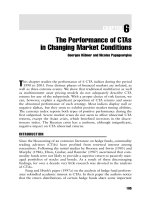
Fig. 1. The use of electrochemical techniques offers the following distinctive
advantages for wastewater treatment [1]:
1. Environmental compatibility. The main reactant is the electron,
which is a clean reagent.
2. Versatility. Electrolytic treatments can deal with solid, liquid, or
gaseous pollutants to generate neutral, positively, or negatively
TM
Copyright © 2003 by Marcel Dekker, Inc. All Rights Reserved.
charged inorganic or organic products, also inducing the pro-
duction of precipitates, gaseous species, pH changes, etc. In ad-
dition, a plethora of reactors and electrode materials, shapes, and
configurations can be utilized [2]. It is noteworthy that the same
reactor can be used frequently for different electrochemical re-
actions with only minor changes, and that electrolytic processes
can be scaled easily from the laboratory to the plant, allowing
treatment volumes ranging from milliliters to millions of liters,
respectively.
3. Safety. Electrochemical methods are generally safe because of the
mild conditions usually employed and the small amount and in-
nocuous nature of the added chemicals.
4. Energy efficiency. Electrochemical processes are amenable to work
at low temperatures and pressures, usually below ambient con-
ditions. Electrodes and cells can also be designed to minimize
power losses due to poor current distribution and voltage drops. In
some instances, the required equipment and operations are simple
and, if properly designed, can be made relatively inexpensively.
Figure 1 Schemes for different electrochemical treatments of organic pollutants.
(a) Direct electrolysis by anodic oxidation in which the pollutant reacts at the
electrode surface with adsorbed OH
.
produced from water oxidation at a high O
2
-
overpotential anode. (b) Indirect electrolysis where the pollutant reacts in the
solution with an irreversibly electrogenerated reagent B
+
produced from the
oxidation of inactive B at the anode.
Brillas et al.236
TM
Copyright © 2003 by Marcel Dekker, Inc. All Rights Reserved.
The electrochemical methods described in this chapter for the
destruction of organics in wastewaters are classified in Fig. 2. The direct
electrolytic processes include conventional procedures of cathodic reduc-
tion and anodic oxidation. The indirect methods deal with the use of
redox mediators as reversibly electrogenerated reagents, as well as
oxidants as irreversibly electrogenerated reagents at the anode (e.g., O
3
,
ClO
À
,Cl
2
, and ClO
2
) or the cathode (e.g., H
2
O
2
). Emerging processes
related to electrogenerated Fenton reagent and other electrochemical
oxidation processes based on the combined use of iron ions and
electrogenerated H
2
O
2
are also described. Other indirect electrolytic
processes include conventional methods of phase separation, such as
electrocoagulation, electroflotation, and electroflocculation. Fundamen-
tals, laboratory experiments, scale-up studies, and environmental/indus-
trial applications for the different electrochemical techniques are discussed
in this chapter.
Figure 2 Classification of electrochemical methods for the destruction of organics
in aqueous wastes.
Electrochemical Methods for Degradation 237
TM
Copyright © 2003 by Marcel Dekker, Inc. All Rights Reserved.
II. CATHODIC REDUCTION
The direct electroreduction of organics on suitable cathodes is a method
that can be utilized for the dechlorination of pollutants in wastewaters.
Many chlorinated organic compounds are produced in the industry and are
used as solvents, refrigerants, pesticides, transformer oils, etc. Because most
of such compounds are nonbiodegradable, they cause major environmental
problems. Often they are found at small concentrations in a wide variety of
wastewaters, and are usually decontaminated by concentration techniques
such as adsorption on activated carbon or extraction by organic solvents. In
fact, the products thus separated have to be further destroyed to avoid
increasing pollution in the environment. Some of the existing methods are
expensive (e.g., Na treatment), or can produce very dangerous by-products
such as dioxins obtained by incineration. The use of cathodic dehalogena-
tion as an alternative method has the following advantages [1,3–5]:
1. The treatment can be performed at ambient temperature.
2. No additional reagents are required.
3. As the chlorine atoms are selectively removed, the resulting dechlo-
rinated compounds can be degraded by a cheaper method such as a
biological treatment.
It has to be taken into account that during the cathodic reduction, H
2
evolution is a common side reaction in aqueous media and, therefore, a
cathode with high hydrogen overpotential is usually selected to obtain
suitable electrodegradation efficiencies [1,6,7]. Moreover, dissolved oxygen
can also be reduced (see Sec. VI). Different materials have been utilized as
cathodes including carbon electrodes, Pb, Hg, Pt, Cu, Ni, Ni alloys, Ni
composites, Ti, TiO
2
, and metal hydrides. Several problems have been
detected in the use of carbon electrodes. Graphite develops fractures along
its basal planes due to the intercalation of ions or organic molecules that
migrate under the electrical field through them. In addition, carbon elec-
trodes can suffer from degradation by radicals formed during the electro-
reduction of dissolved oxygen. Fortunately, these problems are solved using
three-dimensional carbonaceous materials made of partially graphitized
amorphous carbon and graphite felts [8,9]. Problems of stability have also
been found with Pb during the electroreductive dehalogenation of several
chlorinated organic compounds [9,10]. Mercury has several drawbacks,
including the limitation in current densities, probable metal leaks to the
electrolyte, and difficulties in scaling-up with liquid metals.
This section is devoted to the application of cathodic reduction for
treating aliphatic and aromatic pollutants at low concentrations, and also to
the dechlorination of chlorofluorocarbons (CFCs) in aqueous media. The
Brillas et al.238
TM
Copyright © 2003 by Marcel Dekker, Inc. All Rights Reserved.
aromatic pollutants are typically chlorinated compounds that contaminate
wastewaters, whereas CFCs are volatile hydrocarbons with chlorine and
fluorine atoms, which were primarily used as refrigerants and gas propel-
lants. CFCs destroy the stratospheric ozone layer and contribute to the
greenhouse effect. The Montreal Protocol provided an international agree-
ment to stop CFC production beginning in 1996. However, about 2
Â
10
6
tons
of CFCs were still stored in freezing devices in 1999. To avoid probable leaks
to the atmosphere, they should be degraded or converted to useful chemicals.
Because destructive methods such as incineration, UV photolysis, catalytic
decomposition at high temperatures, and solar thermal technology are
expensive and/or can produce dangerous by-products, the partial conversion
of CFCs to useful and harmless compounds is much more attractive.
A. Aliphatic and Aromatic Compounds
Direct electrolysis has been applied successfully to the degradation of
chloroalkanes such as CHCl
3
[11] and CCl
4
[12]. As these compounds react
scarcely with radicals such as OH
Á
and as their toxicity is directly related to
their chlorine content, the reductive dechlorination is especially attractive.
The electrochemical reduction enables the removal of substituents, espe-
cially halogen atoms, along with the hydrogenation of the molecule. The
products are less toxic and more biodegradable and/or sensitive to electro-
chemical oxidation [4,5]. However, an important problem in electrochemical
dehalogenation is the low current efficiency.
These reactions take place at room temperature at potentials of about
À1 V vs. saturated calomel electrode (SCE). The general reaction per
chlorine atom can be written as follows:
R À Cl þ 2H
þ
þ 2e
À
!R À H þ HCl ð1Þ
Sonoyama et al. [11] have studied the electroreductive decomposi-
tion of chloroform on 15 kinds of metal electrodes using a Pyrex cell di-
vided by a glass filter with a cathode area of 16–18 cm
2
. Experiments
performed by electrolyzing 200 mL of deaerated aqueous 0.1 M K
2
SO
4
solution with 6.20 mM CHCl
3
at 1 mA cm
À2
up to a total charge of 50 C
showed a strong dependence of the decomposition efficiency and the main
product formed on the metal tested. The hydrogenation of chloroform on
Ag, Zn, Pd, and Cu cathodes proceeded at near 100% efficiency and the
main product was CH
4
. In contrast, 88% dichloromethane was selectively
generated on Pb.
Scherer et al. [12] studied the kinetics of CCl
4
dechlorination on an
oxide-free iron rotating disk electrode in borate buffer (pH 8.4) at a
potential such that an oxide film would not form. The rate of CCl
4
reduction
Electrochemical Methods for Degradation 239
TM
Copyright © 2003 by Marcel Dekker, Inc. All Rights Reserved.
was dominated by reactions at the metal–solution interface, as is the case in
oxide-covered granular iron.
The electrolysis of chlorinated aromatics and aliphatics at concentra-
tions ranging from 40 to 560 ppm on carbon fiber gives effective dechlo-
rination [3,13]. Several trials were performed at 10 A using 1 L of aqueous
NaOH+Na
2
SO
4
with small additions of methanol or acetonitrile to enhance
the solubility of the pollutant. The cell utilized is illustrated in Fig. 3. The fiber
bundles, containing 50,000 single fibers of 8 Am diameter, are clam ped at the
entrance side. The Pt mesh anode is separated from the cathode by a cation-
permeable NafionR membrane. The current efficiencies obtained were low,
although a value of 75% was found for dichlorvos (Table 1). Despite the
low current efficiencies, the process is feasible at reasonable costs and yields
a high degree of detoxification. The treatment of wastewaters with 50 ppm
pentachlorophenol by electrochemical reduction using C fiber electrodes for
30 min decreased its concentration to below the detection limit of 0.5 ppm
[13]. During the treatment, the toxicity decreased by a factor of 20. The final
reaction products were phenol and, possibly, monochlorophenols.
Many substituted phenols have been electroreduced at Pt electrodes
in ethanol–water mixtures [14] or in acid (0.05 M H
2
SO
4
or 2 M HClO
4
)
solutions [15], leading to cyclohexanols with a current efficiency close to
100%. The reaction appears to proceed via a surface process involving the
adsorption of phenols and hydrogen atoms formed at the cathode. As cyclo-
hexanols are biocompatible, these substituted phenols can be degraded by
Figure 3 Scheme of the flow-through multifiber cell for the electrodechlorination
of organic compounds in wastewaters. (From Ref. 3.)
Brillas et al.240
TM
Copyright © 2003 by Marcel Dekker, Inc. All Rights Reserved.
electroreduction coupled to biological degradation. However, p-nitrophenol
and 4-chlorophenol did not yield cyclohexanols. Phenol can be obtained by
the electroreduction of 4-chlorophenol on a palladized carbon cloth or
palladized graphite cathodes in a divided cell containing acetate buffer [16].
The suggested mechanism involves the adsorption of 4-chlorophenol on the
carbon surface near the carbon/Pd interface, followed by its hydrogenation
with the hydrogen atoms adsorbed on the Pd surface. A complete dechlori-
nation of 25 mL of 153 ppm 4-chlorophenol in 0.05 M sodium acetate acetic
acid buffer at À0.7 V vs. SCE on 2-cm
2
palladized carbon cloth cathode
required 15 hr, during which time the current decreased from 2.2 to 0.8 mA.
Poorer results were obtained when Pt was used instead of Pd.
Chlorinated hydrocarbons have also been reduced on Cu cathodes
in aqueous solutions [7]. In this case, a fixed-bed, flow-through reactor
filled with Cu balls, 0.2–0.6 mm in diameter, supported on a Pt gauze was
employed. Hexachlorocyclohexane was dechlorinated rapidly and com-
pletely. Tetrachloroethylene, trichloroethane, and chlorobenzene were less
reactive. However, unsatisfactory results were obtained with a polychlori-
nated biphenyl (PCB).
The electroreduction of trichloroethylene (0.4 g L
À1
)onCuin0.05M
NaOH was found to be more efficient than on Ag or Cd cathodes [4],
with the current efficiency increasing when the applied current density
decreased. At a current density of 4 mA cm
À2
, the current efficiencies for
the dehalogenation of monochloroacetic acid, dichloroacetic acid, chloro-
form, and trichloroethylene were 2%, 10%, 87%, and 29%, respectively.
5-Chlorosalicylic acid could not be dechlorinated on Cu. Nagaoka et al. [17]
Table 1 Results Obtained for the Electrochemical Dehalogenation in the
Cell Shown in Fig. 3 at 10 A in 1 L of 0.1 M NaOH+0.1 M Na
2
SO
4
Compound
Initial concentration
[ppm]
Number of
Cl removed CE [%]
Energy cost
[kW hr m
À3
]
2-NH
2
-4-Cl-phenol 100 1 0.7 60
4-Cl-C
6
H
4
NO
2
48 1 0.4 55
DDVP
a
560 1(2) 75 0.8
C
2
Cl
6
50 6 1 77
Pentachlorophenol 50 5 2 36
2,4,5-T
b
100 3 1 70
C
2
Cl
4
74 4 3 70
1,2,4-Cl
3
C
6
H
3
40 3 0.7 70
a
Dichlorvos or dimethyl-2,2-dichlorovinyl phosphate.
b
2,4,5-Trichlorophenoxyacetic acid.
Source: Ref. 3.
Electrochemical Methods for Degradation 241
TM
Copyright © 2003 by Marcel Dekker, Inc. All Rights Reserved.
reported the quantitative electroreduction of trichloroethylene in water–
acetonitrile at composite electrodes consisting of metal particles (stainless
steel, Ni, and Cr) and oxidatively treated glassy carbon particles. Trichloro-
ethylene was first reduced to chloroacetylene on the glassy carbon pa rticles,
and the latter was further reduced to acetylene on the metal.
o-Chlorobenzoic acid, which is resistant to anodic oxidation, can be
cathodically reduced on a Pb cathode to o-chlorobenzyl alcohol [18]. This
alcohol was further oxidized to o-chlorobenzaldehyde at a PbO
2
anode. The
extent of its degradation was about 90%. In the presence of MnSO
4
, both
the alcohol and the aldehyde suffer oxidative degradation at the anode
during the electrolysis to yield mainly aliphatic acids.
Funabashi et al. [19] electroreduced iodine-containing organic com-
pounds such as iodotyrosine from medical waste solutions to separate
iodide, which was adsorbed by Ag-coated Al
2
O
3
for effective separation.
Another procedure for the electrochemical dechlorination of pollutants
in aqueous media consists of the use of a corrodible metal or a bimetallic
system without the application of external current. The reaction proceeds as
in corrosion—with the anodic regions being dissolved and with reduction
taking place at cathodic regions. The rate of reduction is lower than in the
case of the cathodic reduction with imposed DC voltage because the
potential of the local cathodes is less negative. However, the dechlorination
rate can be increased with the metal surface area exposed to the wastewater.
A full-scale column reactor has been described by Sweeny [20,21], and this
device has been tested for the treatment of industrial wastewaters using
various combinations of catalyzed Zn, Al, or Fe mixed with sand. The
detoxification of hexachlorocyclopentadiene, trihalomethanes, chloroethy-
lenes, chlorobenzene, chlordane, atrazine, and nitrophenols was reported.
Bachmann et al. [7] employed a suspension of steel grit, covered partially
with Cu by cementation. In this case, Fe was oxidized to Fe(II) whereas the
chlorinated compound was reduced on Cu releasing Cl
À
. Matheson and
Tratnyek [22] sequentially dehalogenated carbon tetrachloride via chloro-
form to methylene chloride on fine-grained iron metal. Trichloroethylene
was also dechlorinated by iron, although more slowly than carbon tetra-
chloride. Grittini et al. [23] have shown the complete dechlorination of PCBs
to biphenyl in an aqueous methanol solution in a few minutes by contacting
the solution with a Pd/Fe system. In this case, the reduction was assumed to
be due to hydrogen adsorbed by Pd during Fe corrosion [16].
B. Chlorofluorocarbons
Electrochemical reduction processes of CFCs leading to partially or com-
pletely dehalogenated compounds for synthetic purposes have been
Brillas et al.242
TM
Copyright © 2003 by Marcel Dekker, Inc. All Rights Reserved.
described in the literature. Many examples in which the CFCs are converted
to hydrochlorofluorocarbons (HCFCs), hydrofluorocarbons (HFCs), and/
or fluorocarbons (FCs) have been reported. HCFCs are not as destructive to
stratospheric ozone; nevertheless, their production will be gradually reduced
to zero in 2020. HFCs and FCs are harmless to stratospheric ozone and
there is currently no limitation for their production.
Edison [24] disclosed the conversion of CFCs to HCFCs, HFCs, and
FCs using a divided cell with a Hg pool cathode in ethanol (60 vol.%)–water
containing potassium acetate. In one example, the conversion of 1,1,2-
trichloro-1,2,2-trifluoroethane (CFC 113) to chlorotrifluoroethene (CTFE),
an industrial monomer, at 20 mA after passing a total charge of 18,700 C
was 64 mol%. The cathodic reaction is:
Cl
2
FC À CF
2
Cl þ 2e
À
!ClFC¼CF
2
þ 2Cl
À
ð2Þ
Cabot et al. [25,26] reported CFC 113 electroreduction in Pb and
Cd cathodes, combined with a hydrogen diffusion anode in MeOH (50–
80 vol.%)–water mixtures with 0.75 M NH
4
Cl and 50 ppm PdCl
2
,with
the MeOH content allowing significant CFC solubility. The current effi-
ciency at 80 and 200 mA cm
À2
was 98%, and difluoroethene and trifluo-
roethene were the main products in the gas phase. H
2
can be selectively
oxidized at the gas diffusion electrode (GDE), and so there is no need for
separators, reducing the energy cost. The process has also been extended
to CFC 11, and derivatives including fluoromethane have been obtained
[27,28].
Inaba et al. [29] have introduced a different cell to work with gaseous
compounds (Fig. 4). A metal-plated solid polymer electrolyte (SPE) com-
posite electrode faces the gas to be reduced. On the other side, the SPE
is in contact with 0.1 M NaOH in which a Pt wire and an Ag/AgCl ref-
erence electrode are immersed. This system permits the electroreduction of
insoluble reactants in water without employing organic solvents. For ex-
ample, 2-chloro-1,1,1,2-tetrafluoroethane (HCFC 124) is transformed into
1,1,1,2-tetrafluoroethane (HFC 134a). The cathodic reaction can be written
as follows:
CF
3
À CHFCl þ H
2
O þ 2e
À
!CF
3
À CFH
2
þ Cl
À
þ OH
À
ð3Þ
This reaction is considered to be catalyzed by active hydrogen atoms
formed on Pd. The product is recovered as a gas mixture, and Cl
À
and
OH
À
ions move to the electrolyte as the counterions of the anion ex-
change membrane.
Delli et al. [30] have studied the electroreduction of dichlorodifluo-
romethane (CFC 12) in aqueous solutions on Pd, Au, Cu, and Ag, chemi-
Electrochemical Methods for Degradation 243
TM
Copyright © 2003 by Marcel Dekker, Inc. All Rights Reserved.
cally deposited on NafionR 117 membranes using a cell similar to that of
Fig. 4. CFC 12 circulates over the metal on one side of the membrane,
while on the other side, there is a 2-M NaOH solution with the Pt anode
and the Ag/AgCl reference electrode. CH
2
F
2
(HFC 32, a new refrigerant)
and CH
4
were obtained on Ag at À1.4 V vs. Ag/AgCl, with current effi-
ciencies of 60% and 30%, respectively. CH
4
was the main product gen-
erated on Au, Pd, and Cu at À1.0 V, with current efficiencies of 14%, 15%,
and 47%, respectively.
Wetproofed porous electrodes, applied previously in fuel cells, have
also been tested as cathodes for electrosynthesis from gaseous and liquid
starting materials with limited solubility in water. The reagent is supplied
through the hydrophobic electrode, which is in contact with an aqueous
electrolyte. They present some attractive advantages over conventional
electrodes because they:
1. Accelerate electrode reactions
2. Lower diffusion limitations significantly
3. Simplify product isolation.
As an example, Table 2 compares the results obtained using a smooth
Cd cathode and a hydrophobicized Cd electrode prepared from powdered
Cd, carbon, acetylene black A-437E, and polytetrafluoroethylene (PTFE)
[31]. The current efficiency and current density increased for smooth Cd
Figure 4 Schematic diagram of the electrolytic cell with a solid polymer electrolyte
composite electrode. SPE=Neosepta AM-1; CE=Pt wire; RE=Ag/AgCl; WEC=
cathode compartment; CEC=anode compartment. (From Ref. 29.)
Brillas et al.244
TM
Copyright © 2003 by Marcel Dekker, Inc. All Rights Reserved.
when ethanol was added to the electrolyte due to the increase in CFC 113
solubility. Higher current densities and efficiencies, however, were found for
the hydrophobicized Cd electrode.
Kornienko et al. [32] have utilized wetproofed electrodes of acetylene
black containing 40 wt.% PTFE to reduce CFC 113 to CTFE in 3 M LiCl at
35jC. The presence of tetraalkylammonium cations considerably facilitates
the reduction process. It is assumed that CFC 113, like other halogenated
compounds, forms a positively charged complex with the tetraalkylammo-
nium cation, which is much more easily reduced than the CFC 113 itself.
The largest effect was found for tetra-n-butylammonium ion (TBA
+
), giving a
96% yield of CTFE. The increase in CTFE current yield is explained by
the shift of potential to less cathodic values and to the displacement of water
molecules by organic cations in the layer next to the electrode because
hydrogen evolution is slower.
Sonoyama and Sakata [33] have electroreduced CFC 12 on 12 kinds
of metal-supported GDEs in a stainless steel autoclave with 1 M NaOH at
7 atm. Fig. 5 shows the cell employed, which is made of polyvinyl chloride
(PVC), due to its high resistance to corrosion by HF. By applying 64 mA
cm
À2
, Cu-, In-, and Pb-supported GDEs gave almost 100% efficiency
without producing H
2
. Zn-, Ag-, Cu-, and In-supported GDEs produced
mainly CH
4
. The Pb-supported GDE induced only dechlorination, and
93% HFC 32 is selectively obtained with 74% faradaic efficiency. The
evolution of faradaic efficiency of products with current density for Cu-
and Pb-supported GDEs is depicted in Fig. 6a and b, respectively. The
same authors [34] have also studied the cathodic reduction of CFC 13 by
using a 1:1 water–MeOH mixture with 1 M NaOH, and by testing 13 kinds
Table 2 Results Obtained for CFC 113 Electrolyses Conducted on a Smooth
Cd Electrode and a Hydrophobicized (15 wt.% PTFE) Cd Electrode
Electrode Electrolyte
Potential
a
[V]
CE for CTFE
[%]
j
[A m
À2
]
Smooth 1 M LiClO
4
À1.7 9.8 19.5
À2.1 2.2 271
1 M LiClO
4
+ 50% EtOH À1.7 36.7 306
À2.1 18.9 450
Hydrophobicized 1 M LiClO
4
À1.7 83.6 1200
À2.1 81.5 1750
a
Potential vs. saturated Ag/AgCl reference electrode.
Source: Ref. 31.
Electrochemical Methods for Degradation 245
TM
Copyright © 2003 by Marcel Dekker, Inc. All Rights Reserved.
Figure 6 Dependence of faradaic efficiency on current density for products
detected in the reduction of CFC 12 using (a) Cu-supported GDE and (b) Pb-
supported GDE. (o) Methane, (D) difluoromethane, (5) chlorodifluoromethane,
and (
w )H
2
. (From Ref. 33.)
Figure 5 Stainless steel autoclave with the electrolysis cell for the electrochemical
reduction of CFC 12 at 7 atm. (From Ref. 33.)
Brillas et al.246
TM
Copyright © 2003 by Marcel Dekker, Inc. All Rights Reserved.
of metal-supported porous carbon GDEs—the best metals being Cu and
Ag. CFC 13 is dechlorinated and defluorinated on the Cu-supported GDE,
where CH
4
and CHF
3
(HFC 23) were primarily formed. Dechlorination
proceeds selectively on the Ag-supported GDE, giving HFC 23 as the main
product. The faradaic efficiencies depend on the current density, pressure of
CFC 13, electrolyte composition, and potential applied to the GDE. The
optimization of these factors allowed the achievement of 78% faradaic
efficiency in the hydrogenation.
III. ANODIC OXIDATION
Direct anodic oxidation is a popular method for the synthesis of many or-
ganic and inorganic compounds. The technique is also capable of removing
organic pollutants from water streams or reservoirs. Unfortunately, the di-
rect oxidation reactions of organics on inert anodes are very slow as a con-
sequence of kinetic limitations. The pollutant degradation is increased in
practice by using a wide variety of electrocatalytic anodes (Pt, IrO
2
, RuO
2
,
undoped and doped PbO
2
, doped SnO
2
, etc.), usually coating a Ti substrate.
When low cell voltages are applied to avoid O
2
evolution, the activity of
such anodes decreases with time because of the adsorption of poisoning
species on their surfaces. These species can be oxidized only at higher
anodic potentials in the region of water discharge with simultaneous O
2
evolution, allowing the regeneration of the anode surface during oxidation
of organics.
A. Fundamentals
There are two main approaches for pollution abatement in wastewaters by
anodic oxidation [35,36]:
1. The electrochemical conversion method, in which refractory or-
ganics are transformed selectively into biodegradable compounds,
usually carboxylic acids. These products can be further removed
using biological treatment [37].
2. The electrochemical combustion (or electrochemical incineration)
method, in which the organics are completely mineralized (i.e.,
oxidized to CO
2
and inorganic ions).
In both cases, relatively high cell voltages are utilized to produce the
simultaneous anodic oxidation of pollutants and water. Experimental results
reveal that several anodes (e.g., Pt, IrO
2
, and RuO
2
) favor the electrochemical
conversion with low current efficiency, whereas others (e.g., doped SnO
2
and
Electrochemical Methods for Degradation 247
TM
Copyright © 2003 by Marcel Dekker, Inc. All Rights Reserved.
PbO
2
) allow electrochemical combustion with higher current efficiency. To
explain this different behavior, Comninellis [35] has proposed a simple
mechanism considering that the anode surface is formed by a metallic oxide
MO
x
. The oxidation process is initiated by the discharge of H
2
O in acid
solution (or OH
À
in alkaline medium) at the anode to yield adsorbed hydroxyl
radical (reaction (4)), which can further undergo an oxygen transfer to the
lattice of the metallic oxide, giving the so-called higher metallic oxide MO
x+1
(reaction (5)).
MO
x
þ H
2
! MO
x
ðOH
Ã
ÞþH
þ
þ e
À
ð4Þ
MO
x
ðOH
Ã
Þ!MO
xþ1
þ H
þ
þ e
À
ð5Þ
This description predicts the existence of ph ysisorbed (adsorbed
OH
.
) and chemisorbed (MO
x+1
) ‘‘ active oxygen’’ at the anode surface.
In the absence of pollutants, both states produce O
2
according to the
following reactions:
MO
x
ðOH
.
Þ!
1
2
O
2
þ MO
x
þ H
þ
þ e
À
ð6Þ
MO
xþ1
!
1
2
O
2
þ MO
x
ð7Þ
When an oxidizable organic species R is present in the solution, the phys-
isorbed ‘‘active oxygen’’ causes predominantly its complete mineralization
(reaction (8)), and the chemisorbed ‘‘active oxygen’’ participates in the
formation of partially oxidized products RO (reaction (9)):
R þ zMO
x
ðOH
.
Þ!CO
2
þ H
2
O þ zMO
x
þ zH
þ
þ ze
À
ð8Þ
R þ MO
xþ1
! RO þ MO
x
ð9Þ
Thus, the electrochemical conversion is favored by anodes having a
concentration of MO
x
(OH
.
) near zero. This condition is achieved if the rate
of transition of oxygen into the metallic oxide lattice by reaction (5) is much
faster than that of hydroxyl radical formation by reaction (4). In contrast,
electrochemical combustion takes place in anodes with high surface con-
centration of hydroxyl radicals because the rate of reaction (5) becomes
insignificant. The current efficiency for both methods then depends on the
relative rate of reaction (8) or reaction (9) to that of the corresponding
oxygen evolution reaction (reaction (6) or reaction (7)).
Electrochemical combustion involves the hydroxylation (reaction (10))
or dehydrogenation (reaction (11)) of organics with hydroxyl radicals. In the
last case, O
2
can react with the resulting organic radical R
.
to give a very
reactive hydroperoxyl radical ROO
.
(reaction (12)), which is able to abstract
Brillas et al.248
TM
Copyright © 2003 by Marcel Dekker, Inc. All Rights Reserved.
a hydrogen atom from another pollutant RVH (reaction (13)). The resulting
organic hydroperoxides ROOH are relatively unstabl e and decompose,
leading to a molecular breakdown with the generation of subseq uent
intermediates. These scission reactions continue until the final generation
of carbon dioxide and inorganic ions:
R þ MO
x
ðOH
.
Þ!ROH
Ã
þ MO
x
ð10Þ
RH þ MO
x
ðOH
.
Þ!R
.
þ MO
x
þ H
2
O ð11Þ
R
.
þ O
2
! ROO
.
ð12Þ
ROO
.
þ R
V
H ! ROOH þ R
.
V
ð13Þ
On the other hand, several experimental parameters have been defined
to quantify the destruction of an organic species in aqueous medium by
anodic oxidation (38–44). Because the main side reaction is O
2
evolution due
to water decomposition, the instantaneous current efficiency (ICE) at a given
time t for its oxidation can be determined from the O
2
flow rate during
electrolysis in the absence (V
0
) and the presence (V
t,org
) of the selected
pollutant as follows:
ICE ¼
V
0
À V
t;org
V
0
ð14Þ
This equation assumes that if all the current during electrolysis is used for the
oxidation of the initial pollutant and its intermediates, then V
t,org
=0 and
ICE=1. When the electrolysis products are soluble in the electrolyte, the ICE
can also be calculated from the change in the chemical oxygen demand (COD)
[in g O
2
dm
À3
] using the relation:
ICE ¼
ðCODÞ
t
ÀðCODÞ
tþDt
ÂÃ
8I Dt
FV ð15Þ
where (COD)
t
and (COD)
t+Dt
are the values of the COD at times t and
t+Dt, respectively; I is the applied constant current [in A]; F is the Faraday
constant [96,487 C mol
À1
]; and V is the volume of the electrolyte [in dm
À3
].
The parameter ICE decreases with time during electrolysis to finally reach a
value of about zero in a total time s. From the ICE–t plot, an average
current efficiency, which is called the electrochemical oxidizability index
(EOI), is obtained:
EOI ¼
m
t
0
ICE dt
s
ð16Þ
Electrochemical Methods for Degradation 249
TM
Copyright © 2003 by Marcel Dekker, Inc. All Rights Reserved.
By calculating the fraction of current that oxidizes EOD species, as op-
posed to the fraction that oxidizes water, the electrochemical oxygen de-
mand (EOD) [in g O
2
g organic
À1
](g
org
) is determined as follows:
EOD ¼
8ðEOIÞIs
Fg
org
ð17Þ
The degree of oxidation (v) of the organic pollutant can then be defined
from the relation:
v ¼
EOD
ðCODÞ
0
 100 ð18Þ
where (COD)
0
is the initial COD value [in g O
2
g
org
À1
]. It can be seen that
the anodic oxidation to CO
2
is more complete as v approaches 100%.
The parameter EOI gives a quantitative estimate of the ease of anodic
oxidation of organic pollutants; that is, the larger is the EOI, the easier it is
to oxidize the species. Table 3 summarizes EOI values for selected aromatic
compounds [40]. Whereas electron-withdrawing groups (–COOH, –NO
2
,
and –SO
3
H) produce low EOI values indicative of a low electron density
available for oxidation, electron-donating groups (–NH
2
) yield high EOI
values due to the increased electron density available. When both types of
groups are present, as in p-aminotoluenesulfonic acid, the electron-donating
group dominates and the benzene derivative has high EOI values. Table 3
also shows that EOD values determined for the degradation of several
compounds at pH 12 are in good agreement with those theoretically found if
maleic acid is considered as the final product of electrolysis.
It must be borne in mind that anodic oxidation need not go all the way
to CO
2
for the process to render the pollutant harmless. Intermediates such
as oxalic acid and maleic acid [37–41] are biodegradable, and therefore are
acceptable as final products. The reduction by 20% of the initial COD is
called a primary degradation because it involves merely a modification of
the initial pollutant. In contrast, if vz70%, the solution is called intrinsically
biodegradable [37]. When the organic pollutant is toxic and/or refractory,
an initial electrochemical treatment can be designed to modify it and make it
amenable for further biological treatment, thus giving a total process of
lower cost. A coupled electrochemical–biological system for water treatment
is schematized in Fig. 7.
Different electrochemical reactors have bee n used for the anodic
oxidation of organic pollutants. They are usually simple batch cylindrical,
tank, or flow reactors that are designed as undivided cells or with separators
between the anolyte (the solution contained in the anode compartment) and
the catholyte (the solution filling the cathode compartment). Divided cells
Brillas et al.250
TM
Copyright © 2003 by Marcel Dekker, Inc. All Rights Reserved.
Table 3 EOI and EOD [in g O
2
g Organic
À1
] of Representative
Aromatic Substrates Determined at pH=12 Using a Pt Anode
Aromatic EOI EOD experimental EOD theoretical
a
0.56
<0.05
0.58
0.10
<0.05
0.55
0.20
1.4
—
1.1
—
—
1.1
1.4
1.38
—
1.20
—
—
0.98
1.36
a
Calculated supposing that maleic acid is the final product of electrolysis.
Source: Ref. 40.
Electrochemical Methods for Degradation 251
TM
Copyright © 2003 by Marcel Dekker, Inc. All Rights Reserved.
can be useful if the cathodic reaction decreases the overall efficiency. For
example, during the oxidation of phenol, p-benzoquinone is produced as an
intermediate that can be reduced at the cathode to hydroquinone, which can
be reoxidized again at the anode, thereby decreasing the efficiency of the
process and requiring a separator between the anode and the cathode. Other
reactors include packed bed cells and plate-and-frame arrangements with
multiple electrodes mounted on a filterpress. When the cell stack contains
more than two electrodes, the electrical connection can be monopolar or
bipolar [2]. The monopolar connection involves an external electrical
contact to each electrode and the application of the cell voltage between
each anode and cathode. These electrodes alternate in the cell and both faces
of each electrode are active, with the same polarity. The monopolar cell
requires a low-voltage, high-current supply. In contrast, the bipolar con-
nection needs only two external electrical contacts to the two end electrodes,
and the voltage applied between them causes the polarization of intermedi-
ate electrodes (see Fig. 10). The opposite faces of each electrode will then
have different polarities. The bipolar cell, in addition to simplicity of
electrical connection, has the advantage of producing the equivalent
amount of products as monopolar cells using many times lower currents
at higher voltages, sometimes leading to a more economic use of power.
However, current leaks between adjacent cells are a typical disadvantage.
The selected electrodes have to take into account the composition
and the nature of the water to be treated, as well as the stability of the
electrode material, its cost, and its environmental compatibility. Because
organic pollutants require high potentials for their anodic oxidation, often
higher than that for water oxidation, the electrode material has to be
chosen carefully to prevent its corrosion under such conditions. Generally,
oxidized noble metal surfaces (e.g., Pt, Ir, and Ru) covering Ti substrates
are suitable for the degradation of organic substances, although their cost
restricts their widespread use. Cheaper substitutes such as oxidized nickel,
Figure 7 Schematic representation of coupled electrochemical–biological system
for wastewater treatment. (From Ref. 37.)
Brillas et al.252
TM
Copyright © 2003 by Marcel Dekker, Inc. All Rights Reserved.
silver (in alkaline electrolytes), and lead can be used in aqueous media. Doped
SnO
2
and PbO
2
anodes with high O
2
evolution potential are also adequate.
Commercially available high surface anodes include graphite, reticulated
vitreous carbon, stainless steel, nickel, and EbonexR (a Ti-based ceramic),
although most of them are useful in only a limited range of potential and pH.
Recently, a synthetic boron-doped diamond thin-film anode suitable for
anodic oxidation of carboxylic acids has been described [44].
We shall now proceed to discuss laboratory-scale experiments related
to the destruction of different types of organic pollutants with significant
environmental applications.
B. Aromatics
Aniline and its derivatives are highly toxic because they can react easily in the
blood with hemoglobin, thereby preventing oxygen uptake. These aromatic
amines are commonly produced as by-products or wastes in the dye, petro-
leum, pulp and paper, coal, perfume, and rubber industries. Kirk et al. [45]
studied the anodic oxidation of aniline in dilute sulfuric acid at pH 2 for
wastewater treatment. Fig. 8 shows the flow system utilized to recirculate the
anolyte (bottom) and a cross-section of the fixed packed bed electrochemical
reactor (top) containing a PbO
2
anode, a stainless steel cathode, and a Nafion
427 cationic membrane as a separator between anolyte and catholyte. The
oxidation of aniline yielded p-benzoquinone (C
6
H
4
O
2
) and maleic acid
(C
4
H
4
O
4
) as intermediates, from the following reactions:
C
6
H
5
NH
2
þ 2H
2
O ! C
6
H
4
O
2
þ 3H
þ
þ 4e
À
þ NH
4
þ
ð19Þ
C
6
H
4
O
2
þ 6H
2
O ! C
4
H
4
O
4
þ 2CO
2
þ 12H
þ
þ 12e
À
ð20Þ
C
4
H
4
O
4
þ 4H
2
O ! 4CO
2
þ 12H
þ
þ 12e
À
ð21Þ
The treatment of 400 mL of 5.5 mM aniline led to 80% decay within 30 min.
After 5 hr, 97% aniline was degraded and 72% was completely mineralized
to CO
2
. The percentage of oxidized aniline increased wi th increasing current
and pH. Further experiments showed best current efficiencies (c40%) at 30
min and at pH 11.
Phenols containing one or more hydroxyl groups are produced as
wastes in a variety of industries, including plastics, oil refining, pharmaceu-
ticals, and dyes. Normally, biological treatment is preferred, although this
is not a viable option for high concentrations or when the effluent has a
variable composition. Chemical oxidation with Fenton reagent (H
2
O
2
in
the presence of Fe
2+
), ozone, or chlorine is used in these cases. Nonetheless,
safety and economic and environmental issues of such chemical oxidizers
have led to the study of alternatives based on anodic oxidation [38–43,46–
50]. A study by Sharifian and Kirk [39] on the degradation of phenol in
Electrochemical Methods for Degradation 253
TM
Copyright © 2003 by Marcel Dekker, Inc. All Rights Reserved.
dilute sulfuric acid using the packed bed reactor shown in Fig. 8 established
the formation of p-benzoquinone and maleic acid as major intermediates
and CO
2
as the main final product. Note that these species were also ob-
tained for aniline oxidation [45] and a similar sequence to reactions 19–22
can be given to interpret the oxidation of phenol. A higher conversion to
CO
2
was achieved by increasing current from 1 to 3 A, but the maximum
current efficiency dropped from around 20% to around 12%. The process
became faster when sulfuric acid concentration increased from 0.1 to 2 M
Figure 8 (Top) Electrochemical flow cell for the oxidation of phenol and aniline:
(a) Pb anode feeder; (b) packed bed of 1-mm lead pellets; (c) stainless steel cathode
plate; (d) Nafion membrane; (e) stainless steel screen; (f) Luggin capillary; (g) glass
beads; (h) gasket; (i) reactor inlet; (j) reactor outlet. (Bottom) Schematic of
apparatus: (a) electrochemical reactor; (b) peristaltic pump; (c) water bath; (d)
heater; (e) anolyte reservoir; (f) gas sparging tube; (g) CO
2
adsorbers. (From Ref. 39.)
Brillas et al.254
TM
Copyright © 2003 by Marcel Dekker, Inc. All Rights Reserved.
(promoting the breakdown of the p-benzoquinone ring) and when using
higher temperatures and dissolved O
2
to accelerate the oxidation rate of
intermediates. The production of CO
2
, however, is somewhat inhibited as
phenol concentration is increased from 3.5 to 56 mM due to the formation of
by-products, leading to a polymeric film at the PbO
2
anode. Such polymeric
films that hinder the electron transfer at the electrode interface can be
prevented when phenol is oxidized more efficiently by incorporation of Bi(V)
sites in PbO
2
film anodes [49].
The anodic oxidation of phenol at a Pt anode has been studied by
Comninellis and Pulgarin [41]. A yellow-br own, electrically conducting
polymeric film is formed at the anode surface at pH > 9, current density
<30 mA cm
À2
, temperature z50 j C, and phenol concentration of 50 mM.
Under these conditions, the phenolate anion (C
6
H
5
O
À
) is oxidized, leading
to the formation of a polyoxyphenylene film. The EOI is independent of the
current, so that the process is not limited by mass transfer. This suggests
that the oxidation occurs by an electrophilic attack of OH
.
on the aromatic
nucleus, which also explains an increase in EOI from 0.078 to 0.143 and in
EOD from 0.99 to 1.41 when the pH increases from near 2 to around 13 at
70jC, because the phenolate ion is more reactive than phenol toward such
an attack. Hydroquinone, catechol, and p-benzoquinone were initially
formed in large amounts and further oxidized into aliphatic acids such as
maleic, fumaric, and oxalic acids, which remained stable in the solution.
These products are similar to those obtained during the oxidation of phenol
with Fentons reagent, yielding about 30% mineralization. Because anodic
oxidation allows more mineralization (up to about 60%), the authors
proposed the two parallel processes depicted in Fig. 9 involving a chemical
reaction of adsorbed OH
.
with organics (r
1
path), or a direct reaction to
CO
2
of adsorbed organics at the anode (r
2
path).
The use of Ti/SnO
2
anodes doped with Sb for the destruction of
phenol has been considered by several authors [43,46,47]. Comninellis and
Pulgarin [43] found that at pH 13, this anode had a very high overpotential
for O
2
evolution, increasing the rate of phenol oxidation in relation to that
of Pt perhaps due to the change in chemical structure of its surface (e.g., by
hydration of the—SnO bond during anodic polarization). At the SnO
2
anode, only very small amounts of hydroquinone, catechol, and p-benzo-
quinone were found as aromatic intermediates, whereas fumaric, maleic,
and oxalic acids were mineralized rapidly. More than 90% of phenol was
oxidized to CO
2
. This behavior was explained by a reaction sequence in
which the pollutant was preferentially adsorbed at the hydrated electrode
surface and further oxidized by adsorbed hydroxyl radicals. The superiority
of doped SnO
2
over Pt and PbO
2
with respect to the anodic oxidation of
phenols and other aromatics and aliphatics has also been reported by Stucki
Electrochemical Methods for Degradation 255
TM
Copyright © 2003 by Marcel Dekker, Inc. All Rights Reserved.
et al. [47], who designed a simple plate-and-frame bipolar reactor with
undivided cells for wastewater treatment using doped SnO
2
-coated Ti
anodes, as illustrated in Fig. 10. The electrodes were platinized on the
cathode side to catalyze H
2
evolution and to prevent corrosion in acidic
media. Because typical EOI values for the oxidation of organics using SnO
2
anodes were 0.3–0.4, the power consumption of the reactor was 40–50 kW
hr for the removal of 1 kg of COD for a cell voltage of 4 V. This treatment
was recommended for COD concentrations between 500 and 15000 ppm. A
disadvantage could be the low stability of doped SnO
2
anodes.
Several chlorophenols have also been degraded by anodic oxidation.
Johnson et al. [51] considered the degradation of 30 mL of a 4-chlorophenol
solution at pH 3–6, using a 5.3-cm
2
surface area Pt wire coated with a
quaternary oxide film containing Ti, Ru, Sn, and Sb oxide, tightly coiled
around a stainless steel cathode with a Nafion membrane as separator. By
applying 0.95 A, solution TOC dropped from an initial value of 59 ppm
to a value of 1 ppm in 24 hr. Twenty-six intermediates were identified, such
as p-benzoquinone, 4-chloro-1,2-dihydroxybenzene, maleic acid, succinic
acid, malonic acid, and the chlo ride, chlorate, and perchlorate anions.
On the other hand, Gattrell and MacDougall [52] used a flow by-cell with
20.4 cm
3
carbon felts as the anode and cathode (see Fig. 11) to oxidize
pentachlorophenol in acetate buffer. By applying 0.35 V vs. Hg/Hg
2
SO
4
to
the anode, 200 mL of 100 ppm pentachlorophenol was completely degraded
Figure 9 Reaction sequence of the electrochemical combustion of phenol. (r
1
)
Chemical reaction of adsorbed hydroxyl radicals with the organic molecule. (r
2
) Elec-
trochemical cold combustion to CO
2
of adsorbed organic molecules. (From Ref. 41.)
Brillas et al.256
TM
Copyright © 2003 by Marcel Dekker, Inc. All Rights Reserved.
in 20 min, whereas about half of the pollutant was removed from 800 mL of
the same solution. When the reaction was carried out on a Pt foil, an
insoluble dimer, collected as an anodic deposit, was produced. These results
suggested that a useful method to remove chlorinated phenols from waste-
waters can be its collection onto electrode surfaces by electrochemically
driven condensation reactions.
C. p-Benzoquinone
The compound p-benzoquinone is one of the most toxic xenobiotics and is
an intermediate in the course of the oxidative degradation of a wide variety
of benzene derivatives. It belongs to an important family of compounds
often present in industrial wastewaters, particularly from photographic
processes. Pulgarin et al. [53] have studied the detoxification of a p-benzo-
quinone solution at pH 2.5 using Ti/IrO
2
and Sb-doped Ti/SnO
2
anodes. A
scheme of the undivided cell used, with a Pt spiral cathode enclosed in a
porcelain pot, is depicted in Fig. 12. The EOI values for the anodes were
0.06 and 0.19, respectively—determined from the electrolysis of a 14.8-mM
pollutant solution at 50 mA cm
À2
. The Ti/IrO
2
anode led to electrochemical
conversion with formation of aliphatic acids such as maleic, fumaric, mes-
oxalic, and oxalic acids, which are only minimally oxidized in this system.
Because these acids are easily biodegradable and nontoxic, it is hypothesized
that a coupled electrochemical–biological system would be effective for
treatment (see Fig. 7). In contrast, a complete mineralization was achieved
from the Sb-doped Ti/SnO
2
anode with a required electrical charge near
Figure 10 Pilot-scale plate-and-frame bipolar reactor for anodic wastewater
treatment. (From Ref. 47.)
Electrochemical Methods for Degradation 257
TM
Copyright © 2003 by Marcel Dekker, Inc. All Rights Reserved.
40 A hr dm
À3
. Recently, the electrochemi cal incineration of p-benzoquinone
in acetate buffer has been reported by Houk et al. [54]. The cell was similar
to that above cited for 4-chlorophenol oxidation (see Sec. III.B), with a Ti or
Pt anode coated with a film of the oxides of Ti, Ru, Sn, and Sb. These
anodes are stable but somewhat less efficient than an Fe(III)-doped PbO
2
film coated on Ti employed in a previous work [55]. The COD of 50 mL of
100 ppm p-benzoquinone decreased from an initial value of 190 to 2 ppm
during 64 hr of electrolysis at 1 A. The major intermediate products
identified were hydroquinone and aliphatic acids including maleic, succinic,
malonic, and acetic acids. The suggested reaction se quence is given in
Fig. 13, where succinic acid is obtained from a cathodic reduction of maleic
acid, which is formed from the breakdown of the dihydroxylated derivative
generated by an attack of adsorbed hydroxyl radicals onto p-benzoquinone.
Further mineralization of succinic acid occurs via its consecutive oxidation
to malonic and acetic acids.
D. Human Wastes
Several investigations [56,57] have been devoted to the electrochemical
treatment of human wastes in an attempt to make possible its electrochemical
combustion. Tennakoon et al. [57] degraded artificial feces/urine mixtures at
90jCina‘‘U’’ tube cell, further scaling up the process to a parallel plate cell
Figure 11 Flow by-cell setup for anodic oxidation of pentachlorophenol. (From
Ref. 52.)
Brillas et al.258
TM
Copyright © 2003 by Marcel Dekker, Inc. All Rights Reserved.
with a high solution flow rate and a packed bed cell with a high surface area/
volume ratio, as illustrated in Fig. 14. The anodes used were Pt for the ‘‘ U’’
cell; graphite, PbO
2
, or Ti/RuO
2
for the parallel plate cell; and Ebonex
particles coated with SnO
2
doped with Sb
2
O
3
for the packed bed cell. The
synthetic fecal mixture was composed of cellulose, oleic acid, casein, KCl,
NaCl, Ca
2
Cl, and the microorganisms Torpulina and Escherichia Coli being
mixed with different proportions of urine. Gases such as CO
2
,H
2
,O
2
,andN
2
were collected as final products in all cases. For the packed bed electro-
chemical reactor system, particles of 0.5–1.0 mm diameter of coated Ebonex,
a solution flow rate of 0.9–1.4 cm sec
À1
through the packed bed, a bed height
of 5–8 cm, and a current density of 5 mA cm
À2
at 12 V comprise an optimum
set of operational parameters. Under these conditions, an energy requirement
of 11.4 kW hr was estimated to deal with the waste of one person in 24 hr. This
technology could be appropriate for water recycling in space missions.
Figure 12 Divided electrolytic cell for the detoxification of p-benzoquinone
solutions in wastewater treatment. (From Ref. 53.)
Electrochemical Methods for Degradation 259
TM
Copyright © 2003 by Marcel Dekker, Inc. All Rights Reserved.