MATHEMATICS MANUAL FOR WATER AND WASTEWATER TREATMENT PLANT OPERATORS - PART pps
Bạn đang xem bản rút gọn của tài liệu. Xem và tải ngay bản đầy đủ của tài liệu tại đây (1.42 MB, 92 trang )
Part III
Wastewater Math Concepts
L1675_C22.fm Page 229 Saturday, January 31, 2004 5:47 PM
© 2004 by CRC Press LLC
231
22
Preliminary Treatment
Calculations
TOPICS
• Screening
• Screening Removal Calculations
• Screening Pit Capacity Calculations
• Grit Removal
• Grit Removal Calculations
• Grit Channel Velocity Calculations
The initial stage of treatment in the wastewater treatment process (following collection and influent
pumping) is
preliminary treatment.
Process selection normally is based upon the expected charac-
teristics of the influent flow. Raw influent entering the treatment plant may contain many kinds of
materials (trash), and preliminary treatment protects downstream plant equipment by removing
these materials, which could cause clogs, jams, or excessive wear in plant machinery. In addition,
the removal of various materials at the beginning of the treatment train saves valuable space within
the treatment plant.
Two of the processes used in preliminary treatment include screening and grit removal; however,
preliminary treatment may also include other processes, each designed to remove a specific type
of material that presents a potential problem for downstream unit treatment processes. These
processes include shredding, flow measurement, preaeration, chemical addition, and flow equaliza-
tion. Except in extreme cases, plant design will not include all of these items. In this chapter, we
focus on and describe typical calculations used in two of these processes: screening and grit removal.
SCREENING
Screening
removes large solids, such as rags, cans, rocks, branches, leaves, and roots, from the
flow before the flow moves on to downstream processes.
S
CREENING
R
EMOVAL
C
ALCULATIONS
Wastewater operators responsible for screenings disposal are typically required to keep a record of
the amount of screenings removed from the flow. To keep and maintain accurate screening records,
the volume of screenings withdrawn must be determined. Two methods are commonly used to
calculate the volume of screenings withdrawn:
(22.1)
(22.2)
Screenings removed cu ft day
screenings cu ft
days
()
=
()
Screenings removed cu ft MG
screenings cu ft
flow MG
()
=
()
()
L1675_C22.fm Page 231 Saturday, January 31, 2004 5:47 PM
© 2004 by CRC Press LLC
232
Mathematics for Water/Wastewater Treatment Plant Operators
Example 22.1
Problem
A total of 65 gallons of screenings is removed from the wastewater flow during a 24-hour period.
What is the screening removal reported as cubic feet per day (cu/ft/day)?
Solution
First, convert gallon screenings to ft
3
Next, calculate screenings removed as cu ft/day:
Example 22.2
Problem
During 1 week, a total of 310 gallons of screenings was removed from wastewater screens. What
is the average removal in cu ft/day?
Solution
First, gallon screenings must be converted to cu ft screenings:
Next, we calculate the screening removal:
S
CREENING
P
IT
C
APACITY
C
ALCULATIONS
Recall that detention time may be considered the time required for flow to pass through a basin or
tank or the time required to fill a basin or tank at a given flow rate. In screening pit capacity
problems, the time required to fill a screening pit is calculated. The equation used in screening pit
capacity problems is given below:
(22.3)
Example 22.3
Problem
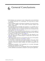
A screening pit has a capacity of 500 cu ft. (The pit is actually larger than 500 cu ft to accommodate
soil for covering.) If an average of 3.4 cu ft of screenings are removed daily from the wastewater
flow, in how many days will the pit be full? See Figure 22.1.
65
87
gal
7.48 gal cu ft
cu ft screenings= .
Screenings removed cu ft day
cu ft
day
cu ft day
()
==
87
1
87
.
.
310
41 4
gal
748 gal cu ft
cu ft screenings= .
Screenings removed cu ft day
cu ft
7 days
cu ft day
()
==
41 4
59
.
.
Screening pit fill time day
volume of pit cu ft
screening removed cu ft day
()
=
()
()
L1675_C22.fm Page 232 Saturday, January 31, 2004 5:47 PM
© 2004 by CRC Press LLC
Preliminary Treatment Calculations
233
Solution
Referring to Equation 22.3:
Example 22.4
Problem
A plant has been averaging a screening removal of 2 cu ft/MG. If the average daily flow is 1.8 MGD,
how many days will it take to fill the pit with an available capacity of 125 cu ft? See Figure 22.2.
Solution
The filling rate must first be expressed as cu ft/day:
Example 22.5
Problem
A screening pit has a capacity of 12 cu yd available for screenings. If the plant removes an average
of 2.4 cu ft of screenings per day, in how many days will the pit be filled? See Figure 22.3.
FIGURE 22.1
Screenings pit. Refers to Example 22.3.
FIGURE 22.2
Screenings pit. Refers to Example 22.4.
500 ft
3
Volume
3.4 ft
3
/day
125 ft
3
Volume
2
ft
3
/MG
Screening pit fill time day
cu ft
cu ft day
days
()
=
=
500
34
147 1
.
.
218
36
125
36
34 7
cu ft MGD
MG
cu ft day
Screening pit fill time days
cu ft
cu ft day
days
¥
=
()
=
=
.
.
.
.
L1675_C22.fm Page 233 Saturday, January 31, 2004 5:47 PM
© 2004 by CRC Press LLC
234
Mathematics for Water/Wastewater Treatment Plant Operators
Solution
Because the filling rate is expressed as cu ft/day, the volume must be expressed as cu ft:
12 cu yd
¥
27 cu ft/cu yd = 324 cu ft
Now calculate fill time using Equation 22.3:
GRIT REMOVAL
The purpose of
grit removal
is to remove inorganic solids (sand, gravel, clay, egg shells, coffee
grounds, metal filings, seeds, and other similar materials) that could cause excessive mechanical wear.
Several processes or devices are used for grit removal, all based on the fact that grit is heavier than
the organic solids, which should be kept in suspension for treatment in following unit processes. Grit
removal may be accomplished in grit chambers or by the centrifugal separation of biosolids. Processes
use gravity/velocity, aeration, or centrifugal force to separate the solids from the wastewater.
G
RIT
R
EMOVAL
C
ALCULATIONS
Wastewater systems typically average 1 to 15 cubic feet of grit per million gallons of flow (sanitary
systems, 1 to 4 cu ft/million gal; combined wastewater systems, from 4 to 15 cu ft/million gals of
flow), with higher ranges during storm events. Generally, grit is disposed of in sanitary landfills,
so, for planning purposes, operators must keep accurate records of grit removal. Most often, the
data are reported as cubic feet of grit removed per million gallons for flow:
(22.4)
Over a given period, the average grit removal rate at a plant (at least a seasonal average) can be
determined and used for planning purposes. Typically, grit removal is calculated as cubic yards,
because excavation is normally expressed in terms of cubic yards:
(22.5)
FIGURE 22.3
Screenings pit. Refers to Example 22.5.
12 yd
3
Volume
2.4
ft
3
/day
Screening pit fill time day
cu ft
cu ft day
days
()
=
=
324
24
135
.
Grit removed cu ft MG
grit volume cu ft
flow MG
()
=
()
()
Cubic yards grit
total grit cu ft
27 cu ft cu yd
=
()
L1675_C22.fm Page 234 Saturday, January 31, 2004 5:47 PM
© 2004 by CRC Press LLC
Preliminary Treatment Calculations
235
Example 22.6
Problem
A treatment plant removes 10 cu ft of grit in 1 day. How many ft
3
of grit are removed per million
gallons if the plant flow is 9 MGD?
Solution
Referring to Equation 22.4:
Example 22.7
Problem
The total daily grit removed for a plant is 250 gallons. If the plant flow is 12.2 MGD, how many
cubic feet of grit are removed per MG flow?
Solution
First, convert gallon grit removed to cu ft:
Next, complete the calculation of cu ft/MG:
Example 22.8
Problem
The monthly average grit removal is 2.5 cu ft/MG. If the monthly average flow is 2,500,000 gpd,
how many cu yards must be available for grit disposal if the disposal pit is to have a 90-day capacity?
Solution
First, calculate the grit generated each day:
The cu ft grit generated for 90 days would be:
Grit removed cu ft MG
cu ft
MG
1.1 cu ft MG
()
=
=
10
9
250
33
gal
7.48 gal cu ft
cu ft=
Grit removed cu ft MG
33 cu ft
MGD
cu ft MGD
()
=
=
12 2
27
.
.
25
25 625
.
cu ft
MG
MGD cu ft each day¥=
625
90 562 5
.
.
cu ft
day
days cu ft¥=
L1675_C22.fm Page 235 Saturday, January 31, 2004 5:47 PM
© 2004 by CRC Press LLC
236
Mathematics for Water/Wastewater Treatment Plant Operators
Convert cu ft to cu yd grit:
G
RIT
C
HANNEL
V
ELOCITY
C
ALCULATION
The optimum velocity in sewers is approximately 2 fps at peak flow, because this velocity normally
prevents solids from settling from the lines; however, when the flow reaches the grit channel, the
velocity should decrease to about 1 fps to permit the heavy inorganic solids to settle. In the example
calculations that follow, we describe how the velocity of the flow in a channel can be determined
by the float and stopwatch method and by channel dimensions.
Example 22.9 (Velocity by Float and Stopwatch)
(22.6)
Problem
It takes a float 30 seconds to travel 37 feet in a grit channel. What is the velocity of the flow in
the channel?
Solution
Example 22.10 (Velocity by Flow and Channel Dimensions)
This calculation can be used for a single channel or tank or for multiple channels or tanks with
the same dimensions and equal flow. If the flow through each unit of the unit dimensions is unequal,
the velocity for each channel or tank must be computed individually.
(22.7)
Problem
A plant is currently using two grit channels. Each channel is 3 ft wide and has a water depth of
1.3 ft. What is the velocity when the influent flow rate is 4.0 MGD?
Solution
ߜ
Key Point:
Because 0.79 is within the 0.7 to 1.4 level, the operator of this unit would not make
any adjustments.
ߜ
Key Point:
The channel dimensions must always be in feet. Convert inches to feet by dividing by
12 inches per foot.
562 5
27
21
. cu ft
cu ft cu yd
cu yd=
Velocity ft second
distance traveled ft
time required seconds
()
=
()
()
Velocity fps
ft
30 sec
fps
()
==
37
12.
Velocity fps
flow MGD cfs MGD
No. channels in service channel width ft water depth ft
()
=
()
¥
¥
()
¥
()
155.
Velocity fps
MGD cfs MGD
channels ft ft
cfs
7.8 ft
fps
2
()
=
¥
¥¥
==
40 155
2313
62
079
.
.
.
L1675_C22.fm Page 236 Saturday, January 31, 2004 5:47 PM
© 2004 by CRC Press LLC
Preliminary Treatment Calculations
237
Example 22.11 (Required Settling Time)
This calculation can be used to determine the time required for a particle to travel from the surface
of the liquid to the bottom at a given settling velocity. To compute the settling time, settling velocity
in ft/sec must be provided or determined by experiment in a laboratory.
(22.8)
Problem
A plant’s grit channel is designed to remove sand, which has a settling velocity of 0.080 fps. The
channel is currently operating at a depth of 2.3 ft. How many seconds will it take for a sand particle
to reach the channel bottom?
Solution
Example 22.12 (Required Channel Length)
This calculation can be used to determine the length of channel required to remove an object with
a specified settling velocity.
(22.9)
Problem
The grit channel of a plant is designed to remove sand, which has a settling velocity of 0.080 fps.
The channel is currently operating at a depth of 3 ft. The calculated velocity of flow through the
channel is 0.85 fps. The channel is 36 ft long. Is the channel long enough to remove the desired
sand particle size?
Solution
Referring to Equation 22.9:
Yes, the channel is long enough to ensure that all the sand will be removed.
Settling time seconds
liquid depth in ft
settling velocity fps
()
=
()
Settling time sec
ft
0.080 fps
sec
()
==
23
28 7
.
.
Required channel length
channel depth ft flow velocity fps
fps
=
()
¥
()
0 080.
Required channel length
ft 0.85 fps
fps
ft=
¥
=
3
0 080
31 6
.
.
L1675_C22.fm Page 237 Saturday, January 31, 2004 5:47 PM
© 2004 by CRC Press LLC
23
Primary Treatment
Calculations
TOPICS
• Process Control Calculations
• Surface Loading Rate (Surface Settling Rate/Surface Overflow Rate)
• Weir Overflow Rate (Weir Loading Rate)
• Biosolids Pumping
• Percent Total Solids (%TS)
• BOD and SS Removal (lb/d)
Primary treatment
(primary sedimentation or clarification) should remove both settleable organic
and floatable solids. Poor solids removal during this step of treatment may cause organic overloading
of the biological treatment processes following primary treatment. Normally, each primary clarifi-
cation unit can be expected to remove 90 to 95% of settleable solids, 40 to 60% of the total
suspended solids, and 25 to 35% of biological oxygen demand (BOD).
PROCESS CONTROL CALCULATIONS
As with many other wastewater treatment plant unit processes, several process control calculations
may be helpful in evaluating the performance of the primary treatment process. Process control
calculations are used in the sedimentation process to determine:
• Percent removal
• Hydraulic detention time
• Surface loading rate (surface settling rate)
• Weir overflow rate (weir loading rate)
• Biosolids pumping
• Percent total solids (% TS)
• BOD and SS removed (lb/day)
In the following sections, we take a closer look at a few of these process control calculations and
example problems.
ߜ
Key Point:
The calculations presented in the following sections allow us to determine values for
each function performed. Again, keep in mind that an optimally operated primary clarifier should have
values in an expected range. Recall that the expected ranges of percent removal for a primary clarifier are:
• Settleable solids, 90–95%
• Suspended solids, 40–60%
• BOD, 25–35%
The expected range of hydraulic detention time for a primary clarifier is 1 to 3 hours. The expected
range of surface loading/settling rate for a primary clarifier is 600 to 1200 gpd/sq ft) (ballpark
estimate). The expected range of weir overflow rate for a primary clarifier is 10,000 to 20,000 gpd/ft.
L1675_C23.fm Page 239 Saturday, January 31, 2004 5:48 PM
© 2004 by CRC Press LLC
S
URFACE
L
OADING
R
ATE
(S
URFACE
S
ETTLING
R
ATE
/S
URFACE
O
VERFLOW
R
ATE
)
Surface loading rate
is the number of gallons of wastewater passing over 1 square foot of tank per
day (see Figure 23.1). This figure can be used to compare actual conditions with design. Plant
designs generally use a surface-loading rate of 300 to 1200 gal/day/sq ft.
(23.1)
Example 23.1
Problem
A circular settling tank has a diameter of 120 feet. If the flow to the unit is 4.5 MGD, what is the
surface loading rate (in gal/day/ft
2
) (see Figure 23.2)?
Solution
Example 23.2
Problem
A circular clarifier has a diameter of 50 ft. If the primary effluent flow is 2,150,000 gpd, what is
the surface overflow rate (in gpd/sq ft)?
FIGURE 23.1
Primary clarifier.
FIGURE 23.2
Refers to Example 23.1.
gpd flow
Square foot area
4,500,000 gpd flow
0.785 ¥ 120¢ ¥ 120¢
Surface loading rate gpd ft
gal day
surface tank area ft
2
2
()
=
()
Surface loading rate
MGD gal MGD
ft ft
gpd ft
2
=
¥
¥¥
=
4 5 1 000 000
0 785 120 120
398
.,,
.
L1675_C23.fm Page 240 Saturday, January 31, 2004 5:48 PM
© 2004 by CRC Press LLC
Solution
ߜ
Key Point:
Remember that area = 0.785
¥
50 ft
¥
50 ft.
Example 23.3
Problem
A sedimentation basin that is 90 ft by 20 ft receives a flow of 1.5 MGD. What is the surface
overflow rate (in gpd/sq ft) (see Figure 23.3)?
W
EIR
O
VERFLOW
R
ATE
(W
EIR
L
OADING
R
ATE
)
A weir is a device used to measure wastewater flow (see Figure 23.4).
Weir overflow rate
(or
weir
loading rate
)
is the amount of water leaving the settling tank per linear foot of water. The result
of this calculation can be compared with design. Normally, weir overflow rates of 10,000 to 20,000
gal/day/ft are used in the design of a settling tank.
(23.2)
ߜ
Key Point:
To calculate weir circumference, use total feet of weir = 3.14
¥
weir diameter (ft).
FIGURE 23.3
Refers to Eample 23.3.
Area = (90 ft) (20 ft)
1,500,000 gpd
Surface overflow rate
flow gpd
area sq ft
ft ft
gpd sq ft
=
()
()
=
¥¥
=
2 150 000
0 785 50 50
1096
,,
.
Surface overflow rate
flow gpd
area sq ft
gpd
90 ft ft
gpd sq ft
=
()
()
=
¥
=
1 500 000
20
833
,,
Weir overflow rate gpd ft
flow gpd
weir length ft
()
=
()
()
L1675_C23.fm Page 241 Saturday, January 31, 2004 5:48 PM
© 2004 by CRC Press LLC
Example 23.4
Problem
A circular settling tank is 80 feet in diameter and has a weir along its circumference. The effluent
flow rate is 2.75 MGD. What is the weir overflow rate in gallons per day per foot?
Solution
ߜ
Key Point:
Notice that 10,947 gal/day/ft is above the recommended minimum of 10,000.
Example 23.5
Problem
A rectangular clarifier has a total of 70 ft of weir. What is the weir overflow rate (in gpd/ft) when
the flow is 1,055,000 gpd?
Solution
B
IOSOLIDS
P
UMPING
Determination of
biosolids pumping
(the quantity of solids and volatile solids removed from the
sedimentation tank) provides accurate information needed for process control of the sedimentation
process:
Solids pumped = Pump rate (gpm)
¥
pump time (min/day)
¥
8.34 lb/gal
¥
% solids (23.3)
Volatile solids (lb/day) = Pump rate
¥
pump time
¥
8.34
¥
% solids
¥
% volatile matter (23.4)
FIGURE 23.4
(a) Weir overflow for rectangular clarifier, (b) weir overflow for circular clarifier.
Flow Rate (gpd)
Flow Rate (gpd)
(A)
(B)
Weir
Weir
Weir overflow rate gpd ft
MGD gal
3.14 ft
gal day ft
()
=
¥
¥
=
2 75 1 000 000
80
10 947
.,,
,
Weir overflow rate
gpd
70 ft
gpd
=
=
1 055 000
15 071
,,
,
L1675_C23.fm Page 242 Saturday, January 31, 2004 5:48 PM
© 2004 by CRC Press LLC
Example 23.6
Problem
A biosolids pump operates 30 minutes per hour. The pump delivers 25 gal/min of biosolids.
Laboratory tests indicate that the biosolids are 5.3% solids and 68% volatile matter. How many
pounds of volatile matter are transferred from the settling tank to the digester? Assume a 24-hour
period.
Solution
Pump time = 30 min/hr
Pump rate = 25 gpm
% solids = 5.3%
% volatile matter = 68%
Volatile solids (lb/day) = 25 gpm
¥
(30 min/hr
¥
24 hr/day)
¥
8.34 lb/gal
¥
0.053
¥
0.68
= 5410 lb/day
P
ERCENT
T
OTAL
S
OLIDS
(%TS)
Problem
A settling tank biosolids sample is tested for solids. The sample and dish weigh 73.79 g. The dish
alone weighs 21.4 g. After drying, the dish with dry solids weighs 22.4 g. What is the percent total
solids (%TS) of the sample?
Solution
BOD
AND
SS R
EMOVED
(lb/d)
To calculate the pounds of BOD or suspended solids (SS) removed each day, we need to know the
mg/L BOD or suspended solids removed and the plant flow. Then, we can use the mg/L to lb/d
equation.
SS removed = mg/L
¥
MGD
¥
8.34 lb/gal (23.5)
Example 23.7
Problem
If 120 mg/L suspended solids are removed by a primary clarifier, how many lb/day suspended
solids are removed when the flow is 6,250,000 gpd?
Solution
SS removed = 120 mg/L
¥
6.25 MGD
¥
8.34 lb/gal = 6255 lb/day
Sample + dish 73.79 g Dish + dry solids 22.4 g
Dish alone –21.4 g
Dish alone –21.4 g
Difference 52.39 g Difference 1.0 g
10
52 39
100 1 9
.
.
%.%
g
g
¥=
L1675_C23.fm Page 243 Saturday, January 31, 2004 5:48 PM
© 2004 by CRC Press LLC
Example 23.8
Problem
The flow to a secondary clarifier is 1.6 MGD. If the influent BOD concentration is 200 mg/L and
the effluent BOD concentration is 70 mg/L, how many pounds of BOD are removed daily?
Solution
BOD removed (lb/day) = 200 mg/L – 70 mg/L = 130 mg/L
After calculating mg/L BOD removed, calculate lb/day BOD removed:
BOD removed (lb/day) = 130 mg/L
¥
1.6 MGD
¥
8.34 lb/gal = 1735 lb/day
L1675_C23.fm Page 244 Saturday, January 31, 2004 5:48 PM
© 2004 by CRC Press LLC
24
Trickling Filter Calculations
TOPICS
• Trickling Filter Process Calculations
• Hydraulic Loading Rate
• Organic Loading Rate
• BOD and SS Removal
• Recirculation Ratio
The
trickling filter process
(see Figure 24.1) is one of the oldest forms of dependable biological
treatment for wastewater. By its very nature, the trickling filter has advantages over other unit
processes. For example, it is a very economical and dependable process for treatment of wastewater
prior to discharge. Capable of withstanding periodic shock loading, process energy demands are
low because aeration is a natural process. As shown in Figure 24.2, the trickling filter operation
involves spraying wastewater over a solid media such as rock, plastic, or redwood slats (or laths).
As the wastewater trickles over the surface of the media, a growth of microorganisms (bacteria,
protozoa, fungi, algae, helminths or worms, and larvae) develops. This growth is visible as a shiny
slime very similar to the slime found on rocks in a stream. As wastewater passes over this slime,
the slime adsorbs the organic (food) matter. This organic matter is used for food by the microor-
ganisms. At the same time, air moving through the open spaces in the filter transfers oxygen to the
wastewater. This oxygen is then transferred to the slime to keep the outer layer aerobic. As the
microorganisms use the food and oxygen, they produce more organisms, carbon dioxide, sulfates,
nitrates, and other stable byproducts; these materials are then discarded from the slime back into
the wastewater flow and are carried out of the filter.
TRICKLING FILTER PROCESS CALCULATIONS
Several calculations are useful in the operation of trickling filters: these include hydraulic loading,
organic loading, and biochemical oxygen demand (BOD) and suspended solids (SS) removal. Each
type of trickling filter is designed to operate with specific loading levels. These levels very greatly
depending on the filter classification. To operate the filter properly, filter loading must be within
the specified levels. The three main loading parameters for the trickling filter are hydraulic loading,
organic loading, and recirculation ratio.
H
YDRAULIC
L
OADING
R
ATE
Calculating the
hydraulic loading rate
is important to accounting for both the primary effluent as
well as the recirculated trickling filter effluent. These quantities are combined before being applied
to the filter surface. The hydraulic loading rate is calculated based on filter surface area. The normal
hydraulic loading rate ranges for standard rate and high rate trickling filters are:
• Standard rate, 25 to 100 gpd/sq ft or 1 to 40 MGD/acre
• High rate, 100 to 1000 gpd/sq ft or 4 to 40 MGD/acre
ߜ
Key Point:
If the hydraulic loading rate for a particular trickling filter is too low, septic conditions
will begin to develop.
L1675_C24.fm Page 245 Saturday, January 31, 2004 5:50 PM
© 2004 by CRC Press LLC
246
Mathematics for Water/Wastewater Treatment Plant Operators
Example
24.1
Problem
A trickling filter that is 80 ft in diameter is operated with a primary effluent of 0.588 MGD and a
recirculated effluent flow rate of 0.660 MGD. Calculate the hydraulic loading rate on the filter (in
gpd/ft
2
).
Solution
The primary effluent and recirculated trickling filter effluent are applied together across the surface
of the filter; therefore, 0.588 MGD + 0.660 MGD = 1.248 MGD = 1,248,000 gpd.
FIGURE 24.1
Trickling filter system.
FIGURE 24.2
Cross-section of a trickling filter.
Influent
Screen
Primary
Settling
Secondary
Clarifier
Chlorine
Trickling
Filter
Out
Digester Digester Drying Beds Disposal/Reuse
Recirc.
Rock Bed
Influent
Influent Spray
Rotating Arm
Effluent
Underdrain
System
Circular surface area diameter
ft
ft
gpd
5024 ft
gpd ft
=¥
()
=¥
()
=
=
0 785
0 785 80
5024
1 248 000
248 4
2
2
2
2
2
.
.
,,
.
L1675_C24.fm Page 246 Saturday, January 31, 2004 5:50 PM
© 2004 by CRC Press LLC
Trickling Filter Calculations
247
Example
24.2
Problem
A trickling filter that is 80 ft in diameter treats a primary effluent flow of 550,000 gpd. If the
recirculated flow to the clarifier is 0.2 MGD, what is the hydraulic loading on the trickling filter?
Solution
Example
24.3
Problem
A high-rate trickling filter receives a daily flow of 1.8 MGD. What is the dynamic loading rate in
MGD/acre if the filter is 90 ft in diameter and 5 ft deep?
Solution
ߜ
Key Point:
When hydraulic loading rate is expressed as MGD per acre, this is still an expression
of gallon flow over surface area of trickling filter.
O
RGANIC
L
OADING
R
ATE
Trickling filters are sometimes classified by the
organic loading rate
applied. The organic loading
rate is expressed as a certain amount of BOD applied to a certain volume of media. In other words,
the organic loading is defined as the pounds of BOD or chemical oxygen demand (COD) applied
per day per 1000 cubic feet of media — a measure of the amount of food being applied to the
filter slime. To calculate the organic loading on the trickling filter, two things must be known: the
pounds of BOD or COD being applied to the filter media per day and the volume of the filter media
in units of 1000 cubic feet. The BOD and COD contribution of the recirculated flow is not included
in the organic loading.
Example
24.4
Problem
A trickling filter that is 60 ft in diameter receives a primary effluent flow rate of 0.440 MGD.
Calculate the organic loading rate in units of pounds of BOD applied per day per 1000 ft
3
of media
volume. The primary effluent BOD concentration is 80 mg/L. The media depth is 9 ft.
Hydraulic loading rate
total flow gpd
area sq ft
gpd total flow
ft ft
gpd sq ft
=
()
()
=
¥¥
=
750 000
0 785 80 80
149
,
.
0 785 90 90 6359
6359
43 560
0 146
18
0 146
12 3
.
,
.
.
.
.
¥¥
()
=
=
==
ft ft sq ft
sq ft
sq ft ac
acres
Hydraulic loading rate
MGD
acres
MGD ac
L1675_C24.fm Page 247 Saturday, January 31, 2004 5:50 PM
© 2004 by CRC Press LLC
248
Mathematics for Water/Wastewater Treatment Plant Operators
Solution
0.440 MGD
¥
80 mg/L
¥
8.34 lb/gal = 293.6 lb of BOD applied/d
Surface area = 0.785
¥
(60)
2
= 2826 ft
2
Area
¥
depth
¥
volume = cu ft
2826 ft
2
¥
9 ft = 25,434 cu ft (TF volume)
ߜ
Key Point:
To determine the pounds of BOD per 1000 ft
3
in a volume of thousands of cubic feet,
we must set up the equation as shown below:
Regrouping the numbers and the units together:
BOD
AND
SS R
EMOVED
To calculate the pounds of BOD or suspended solids removed each day, we need to know the mg/L
BOD and SS removed and the plant flow.
Example
24.5
Problem
If 120 mg/L suspended solids are removed by a trickling filter, how many lb/day of suspended
solids are removed when the flow is 4.0 MGD?
Solution
mg/L
¥
MGD flow
¥
8.34 lb/gal = lb/day
120 mg/L
¥
4.0 MGD
¥
8.34 lb/gal = 4003 lb SS/day
Example
24.6
Problem
The 3,500,000-gpd influent flow to a trickling filter has a BOD content of 185 mg/L. If the trickling
filter effluent has a BOD content of 66 mg/L, how many pounds of BOD are removed daily?
Solution
mg/L
¥
MGD flow
¥
8.34 lb/gal = lb/day removed
185 mg/L – 66 mg/L = 119 mg/L
119 mg/L
¥
3.5 MGD
¥
8.34 lb/gal = 3474 lb/day removed
293 6 1000
1000
3
. lb BOD d
25,434 ft
¥
293 6 1000
25 434 1000
11 5
1000
33 3
.
,
.
lb BOD d
ft
lb BOD d
ft
lb BOD d
ft
¥
¥=¥
L1675_C24.fm Page 248 Saturday, January 31, 2004 5:50 PM
© 2004 by CRC Press LLC
Trickling Filter Calculations
249
R
ECIRCULATION
R
ATIO
Recirculation
in trickling filters involves the return of filter effluent back to the head of the trickling
filter. It can level flow variations and assist in solving operational problems, such as ponding, filter
flies, and odors. The operator must check the rate of recirculation to ensure that it is within design
specifications. Rates above design specifications indicate hydraulic overloading; rates under design
specifications indicate hydraulic underloading. The
trickling filter recirculation ratio
is the ratio of
the recirculated trickling filter flow to the primary effluent flow. The trickling filter recirculation
ratio may range from 0.5:1 (.5) to 5:1 (5); however, the ratio is often found to be 1:1 or 2:1.
(24.1)
Example
24.7
Problem
A treatment plant receives a flow of 3.2 MGD. If the trickling filter effluent is recirculated at the
rate of 4.5 MGD, what is the recirculation ratio?
Solution
Referring to Equation 24.1:
Example
24.8
Problem
A trickling filter receives a primary effluent flow of 5 MGD. If the recirculated flow is 4.6 MGD,
what is the recirculation ratio?
Solution
Again referring to Equation 24.1:
Recirculation ratio
recirculated flow MGD
primary effluent flow MGD
=
()
()
Recirculation ratio
MGD
MGD
=
=
45
32
14
.
.
.
Recirculation ratio
MGD
MGD
=
=
46
5
092
.
.
L1675_C24.fm Page 249 Saturday, January 31, 2004 5:50 PM
© 2004 by CRC Press LLC
25
Rotating Biological
Contactors (RBCs)
TOPICS
• RBC Process Control Calculations
• Hydraulic Loading Rate
• Soluble BOD
• Organic Loading Rate
• Total Media Area
The
rotating biological contactor
(RBC)
is a variation of the attached growth idea provided by the
trickling filter (see Figure 25.1). Although still relying on microorganisms that grow on the surface
of a medium, the RBC is a
fixed-film
biological treatment device. The basic biological process,
however, is similar to that occurring in trickling filters. An RBC consists of a series of closely
spaced (mounted side by side), circular, plastic, synthetic disks, typically about 11.5 ft in diameter
(see Figure 25.2). Attached to a rotating horizontal shaft, approximately 40% of each disk is
submersed in a tank that contains the wastewater to be treated. As the RBC rotates, the attached
biomass film (zoogleal slime) that grows on the surface of the disks moves into and out of the
wastewater. While they are submerged in the wastewater, the microorganisms absorb organics;
while they are rotated out of the wastewater, they are supplied with needed oxygen for aerobic
decomposition. As the zoogleal slime re-enters the wastewater, excess solids and waste products
are stripped off the media as
sloughings
.
These sloughings are transported with the wastewater
flow to a settling tank for removal.
RBC PROCESS CONTROL CALCULATIONS
Several process control calculations may be useful in the operation of an RBC, including soluble
BOD, total media area, organic loading rate, and hydraulic loading. Settling tank calculations and
biosolids pumping calculations may be helpful for evaluation and control of the settling tank
following the RBC.
H
YDRAULIC
L
OADING
R
ATE
The manufacturer normally specifies the RBC media surface area, and the hydraulic loading rate is
based on the media surface area, usually in square feet (ft
2
). Hydraulic loading is expressed in terms
of gallons of flow per day per square foot of media. This calculation can be helpful in evaluating
the current operating status of the RBC. Comparison with design specifications can determine if the
unit is hydraulically over- or underloaded. Hydraulic loading on an RBC can range from 1 to 3 gpd/ft
2
.
Example
25.1
Problem
An RBC treats a primary effluent flow rate of 0.244 MGD. What is the hydraulic loading rate in
gpd/ft
2
if the media surface area is 92,600 ft
2
?
L1675_C25.fm Page 251 Saturday, January 31, 2004 5:52 PM
© 2004 by CRC Press LLC
252
Mathematics for Water/Wastewater Treatment Plant Operators
Solution
Example
25.2
Problem
An RBC treats a flow of 3.5 MGD. The manufacturer’s data indicate a media surface area of
750,000 sq ft. What is the hydraulic loading rate on the RBC?
Solution
Example
25.3
Problem
A rotating biological contactor treats a primary effluent flow of 1,350,000 gpd. The manufacturer’s
data indicate that the media surface area is 600,000 sq ft. What is the hydraulic loading rate on the filter?
FIGURE 25.1
Rotating biological contactor (RBC) treatment system.
FIGURE 25.2
Rotating biological contactor (RBC) cross-section and treatment system.
Influent
Rotating Biological Contactors
Effluent
Primary
Settling
Tanks
Secondary
Settling
Tanks
Solids Disposal
Cl
2
Media
Zoogleal Slime
Organic
Matter
Wastewater Holding Tank
Oxygen
Sloughings
244 000
92 000
263
2
2
,
,
.
gpd
ft
gpd ft=
Hydraulic loading rate
flow gpd
media area sq ft
gpd
sq ft
sq ft
=
()
()
==
3 500 000
750 000
47
,,
,
.
L1675_C25.fm Page 252 Saturday, January 31, 2004 5:52 PM
© 2004 by CRC Press LLC
Rotating Biological Contactors (RBCs)
253
S
OLUBLE
BOD
The
soluble BOD
concentration of the RBC influent can be determined experimentally in the
laboratory, or it can be estimated using the suspended solids concentration and the
K
factor, which
is used to approximate the BOD (particulate BOD) contributed by the suspended matter. The
K
factor must be provided or determined experimentally in the laboratory. The
K
factor for domestic
wastes is normally in the range of 0.5 to 0.7.
Soluble BOD
5
= Total BOD
5
– (
K
factor
¥
total suspended solids) (25.1)
Example
25.4
Problem
The suspended solids concentration of a wastewater is 250 mg/L. If the
K
value at the plant is 0.6,
what is the estimated particulate BOD concentration of the wastewater?
Solution
ߜ
Key Point:
A
K
value of 0.6 indicates that about 60% of the suspended solids are organic suspended
solids (particulate BOD).
250 mg/L
¥
0.6 = 150 mg/L particulate BOD
Example
25.5
Problem
A rotating biological contactor receives a flow of 2.2 MGD with a BOD content of 170 mg/L and
suspended solids (SS) concentration of 140 mg/L. If the
K
value is 0.7, how many pounds of soluble
BOD enter the RBC daily?
Solution
Now lb/day soluble BOD can be determined:
Soluble BOD (mg/L)
¥
MGD Flow
¥
8.34 lb/gal = lb/day
Soluble BOD (lb/day) = 72 mg/L x 2.2 MGD
¥
8.34 lb/gal = 1321 lb/day
Hydraulic loading rate
flow gpd
area sq ft
gpd
sq ft
sq ft
=
()
()
==
1 350 000
600 000
23
,,
,
.
Total BOD particulate BOD soluble BOD
mg L mg L mg L
mg L mg L mg L
mg L mg L
mg L soluble BOD
=+
=¥
()
+
=+
-=
=
170 140 0 7
170 98
170 98
72
. x
x
x
x
L1675_C25.fm Page 253 Saturday, January 31, 2004 5:52 PM
© 2004 by CRC Press LLC
254
Mathematics for Water/Wastewater Treatment Plant Operators
Example
25.6
Problem
The wastewater entering a rotating biological contactor has a BOD content of 210 mg/L. The
suspended solids content is 240 mg/L. If the
K
value is 0.5, what is the estimated soluble BOD
(mg/L) of the wastewater?
Solution
O
RGANIC
L
OADING
R
ATE
The
organic loading rate
can be expressed as total BOD loading in pounds per day per 1000 square
feet of media. The actual values can then be compared with plant design specifications to determine
the current operating condition of the system.
(25.2)
Example
25.7
Problem
An RBC has a media surface area of 500,000 sq ft and receives a flow of 1,000,000 gpd. If the
soluble BOD concentration of the primary effluent is 160 mg/L, what is the organic loading on the
RBC in lb/day/1000 sq ft?
Solution
Referring to Equation 25.2,
Example
25.8
Problem
The wastewater flow to an RBC is 3,000,000 gpd. The wastewater has a soluble BOD concentration
of 120 mg/L. The RBC consists of six shafts (each 110,000 sq ft), with two shafts comprising the
first stage of the system. What is the organic loading rate in lb/d/1000 sq ft on the first stage of
the system?
Total BOD mg L particulate BOD mg L soluble BOD mg L
mg L
BOD
mg L
SS
mg L
Soluble BOD
mg L mg L mg L
Soluble BOD
Soluble BOD mg L
()
=
()
+
()
=¥
()
+
=+
-=
=
210 240 0 5
210 120
210 120
90
. x
x
x
x
Organic loading rate
soluble BOD flow MGD lb gal
media area sq ft
=
¥
()
¥
()
834
1000
.
Organic loading rate
mg L MGD lb gal
sq ft
lb day soluble BOD
sq ft
=
¥¥
()
=
160 10 834
500 000
27
1000
,
.
L1675_C25.fm Page 254 Saturday, January 31, 2004 5:52 PM
© 2004 by CRC Press LLC
Rotating Biological Contactors (RBCs)
255
Solution
Again referring to Equation 25.2:
T
OTAL
M
EDIA
A
REA
Several process control calculations for the RBC use the total surface area of all the stages within
the train. As was the case with the soluble BOD calculation, plant design information or information
supplied by the unit manufacturer must provide the individual stage areas (or the total train area),
because physical determination of this would be extremely difficult.
Total area = first stage area + second stage area + … +
n
th stage area (25.3)
Organic loading rate
mg L MGD lb gal
sq ft
lb soluble BOD day 1000 sq ft
=
¥¥
()
¥
=
120 30 834
220 1000
13 6
.
L1675_C25.fm Page 255 Saturday, January 31, 2004 5:52 PM
© 2004 by CRC Press LLC
26
Activated Biosolids
TOPICS
• Activated Biosolids Process Control Calculations
• Moving Averages
• BOD or COD Loading
• Solids Inventory
• Food-to-Microorganism Ratio (F/M Ratio)
• Gould Biosolids Age
• Mean Cell Residence Time (MCRT)
• Estimating Return Rates from SSV
60
• Sludge Volume Index (SVI)
• Mass Balance: Settling Tank Suspended Solids
• Biosolids Waste Based Upon Mass Balance
• Oxidation Ditch Detention Time
The
activated biosolids process
is a manmade process that mimics the natural self-purification
process that takes place in steams. In essence, we can state that the activated biosolids treatment
process is a “stream in a container.” In wastewater treatment, activated biosolids processes are used
for both secondary treatment and complete aerobic treatment without primary sedimentation.
Activated biosolids refers to biological treatment systems that use a suspended growth of organisms
to remove BOD and suspended solids.
The basic components of an activated biosolids sewage treatment system include an aeration
tank and a secondary basin, settling basin, or clarifier (see Figure 26.1). Primary effluent is mixed
with settled solids recycled from the secondary clarifier and this mixture is then introduced into
the aeration tank. Compressed air is injected continuously into the mixture through porous diffusers
located at the bottom of the tank, usually along one side.
Wastewater is fed continuously into an aerated tank, where the microorganisms metabolize and
biologically flocculate the organics. Microorganisms (activated biosolids) are settled from the
aerated mixed liquor under quiescent conditions in the final clarifier and are returned to the aeration
tank. Left uncontrolled, the number of organisms would eventually become too great; therefore,
some must be removed periodically (wasted). A portion of the concentrated solids from the bottom
of the settling tank must be removed form the process (waste-activated sludge, or WAS). Clear
supernatant from the final settling tank is the plant effluent.
ACTIVATED BIOSOLIDS PROCESS CONTROL CALCULATIONS
As with other wastewater treatment unit processes, process control calculations are important tools
used by operators to control and optimize process operations. In this chapter, we review many of
the most frequently used activated biosolids process calculations.
M
OVING
A
VERAGES
When performing process control calculations, the use of a seven-day
moving average
is recom-
mended. The moving average is a mathematical method to level the impact of any one test result.
L1675_C26.fm Page 257 Saturday, January 31, 2004 5:53 PM
© 2004 by CRC Press LLC