Modern Physical Metallurgy and Materials Engineering Part 2 pps
Bạn đang xem bản rút gọn của tài liệu. Xem và tải ngay bản đầy đủ của tài liệu tại đây (453.63 KB, 30 trang )
Atomic arrangements in materials 21
The transition can be abrupt but is often sluggish. For-
tunately, tetragonal tin can persist in a metastable state
at temperatures below the nominal transition temper-
ature. However, the eventual transition to the friable
low-density cubic form can be very sudden.
1
Using the concept of a unit cell, together with data
on the atomic mass of constituent atoms, it is possible
to derive a theoretical value for the density of a pure
single crystal. The parameter a for the bcc cell of pure
iron at room temperature is 0.286 64 nm. Hence the
volume of the unit cell is 0.023 55 nm
3
. Contrary to
first impressions, the bcc cell contains two atoms, i.e.
8 ð
1
8
atom C 1 atom. Using the Avogadro constant
N
A
,
2
we can calculate the mass of these two atoms as
255.85/N
A
or 185.46 ð10
24
kg, where 55.85 is the
relative atomic mass of iron. The theoretical density
(mass/volume) is thus 7875 kg m
3
. The reason for
the slight discrepancy between this value and the
experimentally-determined value of 7870 kg m
3
will
become evident when we discuss crystal imperfections
in Chapter 4.
2.5.2 Diamond and graphite
It is remarkable that a single element, carbon, can exist
in two such different crystalline forms as diamond
and graphite. Diamond is transparent and one of the
1
Historical examples of ‘tin plague’ abound (e.g. buttons,
coins, organ pipes, statues).
2
The Avogadro constant N
A
is 0.602 217 ð 10
24
mol
1
.
The mole is a basic SI unit. It does not refer to mass and
has been likened to terms such as dozen, score, gross, etc.
By definition, it is the amount of substance which contains
as many elementary units as there are atoms in 0.012 kg of
carbon-12. The elementary unit must be specified and may
be an atom, a molecule, an ion, an electron, a photon, etc.
or a group of such entities.
hardest materials known, finding wide use, notably as
an abrasive and cutting medium. Graphite finds general
use as a solid lubricant and writing medium (pencil
‘lead’). It is now often classed as a highly refractory
ceramic because of its strength at high temperatures
and excellent resistance to thermal shock.
We can now progress from the earlier representation
of the diamond structure (Figure 1.3c) to a more real-
istic version. Although the structure consists of two
interpenetrating fcc sub-structures, in which one sub-
structure is slightly displaced along the body diagonal
of the other, it is sufficient for our purpose to concen-
trate on a representative structure cell (Figure 2.13a).
Each carbon atom is covalently bonded to four equidis-
tant neighbours in regular tetrahedral
3
coordination
(CN D 4). For instance, the atom marked X occupies a
‘hole’, or interstice, at the centre of the group formed
by atoms marked 1, 2, 3 and 4. There are eight equiv-
alent tetrahedral sites of the X-type, arranged four-
square within the fcc cell; however, in the case of
diamond, only half of these sites are occupied. Their
disposition, which also forms a tetrahedron, maximizes
the intervening distances between the four atoms. If the
fcc structure of diamond depended solely upon pack-
ing efficiency, the coordination number would be 12;
actually CN D 4, because only four covalent bonds can
form. Silicon Z D 14, germanium Z D 32 and grey
tin Z D 50 are fellow-members of Group IV in the
Periodic Table and are therefore also tetravalent. Their
crystal structures are identical in character, but obvi-
ously not in dimensions, to the diamond structure of
Figure 2.13a.
3
The stability and strength of a tetrahedral form holds a
perennial appeal for military engineers: spiked iron caltrops
deterred attackers in the Middle Ages and concrete
tetrahedra acted as obstacles on fortified Normandy beaches
in World War II.
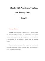
Figure 2.13 Two crystalline forms of carbon: (a) diamond and (b) graphite (from Kingery, Bowen and Uhlmann, 1976; by
permission of Wiley-Interscience).
22 Modern Physical Metallurgy and Materials Engineering
Graphite is less dense and more stable than dia-
mond. In direct contrast to the cross-braced structure of
diamond, graphite has a highly anisotropic layer struc-
ture (Figure 2.13b). Adjacent layers in the ABABAB
sequence are staggered; the structure is not cph. A
less stable rhombohedral ABCABC sequence has been
observed in natural graphite. Charcoal, soot and lamp-
black have been termed ‘amorphous carbon’; actually
they are microcrystalline forms of graphite. Covalent-
bonded carbon atoms, 0.1415 nm apart, are arranged
in layers of hexagonal symmetry. These layers are
approximately 0.335 nm apart. This distance is rel-
atively large and the interlayer forces are therefore
weak. Layers can be readily sheared past each other,
thus explaining the lubricity of graphitic carbon. (An
alternative solid lubricant, molybdenum disulphide,
MoS
2
, has a similar layered structure.).
The ratio of property values parallel to the a-axis
and the c-axis is known as the anisotropy ratio. (For
cubic crystals, the ratio is unity.) Special synthesis
techniques can produce near-ideal graphite
1
with an
anisotropy ratio of thermal conductivity of 200.
2.5.3 Coordination in ionic crystals
We have seen in the case of diamond how the joining
of four carbon atoms outlines a tetrahedron which is
smaller than the structure cell (Figure 2.13a). Before
examining some selected ionic compounds, it is neces-
sary to develop this aspect of coordination more fully.
This approach to structure-building concerns packing
and is essentially a geometrical exercise. It is sub-
ordinate to the more dominant demands of covalent
bonding.
In the first of a set of conditional rules, assembled by
Pauling, the relative radii of cation r and anion R
are compared. When electrons are stripped from the
outer valence shell during ionization, the remaining
1
Applications range from rocket nozzles to bowl linings for
tobacco pipes.
electrons are more strongly attracted to the nucleus;
consequently, cations are usually smaller than anions.
Rule 1 states that the coordination of anions around
a reference cation is determined by the geometry
necessary for the cation to remain in contact with
each anion. For instance, in Figure 2.14a, a radius
ratio r/R of 0.155 signifies touching contact when
three anions are grouped about a cation. This critical
value is readily derived by geometry. If the r/R ratio
for threefold coordination is less than 0.155 then the
cation ‘rattles’ in the central interstice, or ‘hole’, and
the arrangement is unstable. As r/R exceeds 0.155 then
structural distortion begins to develop.
In the next case, that of fourfold coordination,
the ‘touching’ ratio has a value of 0.225 and
joining of the anion centres defines a tetrahedron
(Figure 2.14b). For example, silicon and oxygen ions
have radii of 0.039 nm and 0.132 nm, respectively,
hence r/R D 0.296. This value is slightly greater than
the critical value of 0.225 and it follows that tetrahedral
coordination gives a stable configuration; indeed, the
complex anion SiO
4
4
is the key structural feature
of silica, silicates and silica glasses. The quadruple
negative charge is due to the four unsatisfied oxygen
bonds which project from the group.
In a feature common to many structures, the
tendency for anions to distance themselves from each
other as much as possible is balanced by their attraction
towards the central cation. Each of the four oxygen
anions is only linked by one of its two bonds to
the silicon cation, giving an effective silicon/oxygen
ratio of 1:2 and thus confirming the stoichiometric
chemical formula for silica, SiO
2
. Finally, as shown in
Figure 2.14c, the next coordination polyhedron is an
octahedron for which r/R D 0.414. It follows that each
degree of coordination is associated with a nominal
range of r/R values, as shown in Table 2.2. Caution
is necessary in applying these ideas of geometrical
packing because (1) range limits are approximative,
(2) ionic radii are very dependent upon CN, (3) ions
can be non-spherical in anisotropic crystals and
Figure 2.14 Nesting of cations within anionic groups.
Atomic arrangements in materials 23
Table 2.2 Relation between radius ratio and coordination
r/R Maximum Form of
coordination coordination
number (CN)
<0.155 2 Linear
0.155–0.225 3 Equilateral triangle
0.225–0.414 4 Regular tetrahedron
0.414–0.732 6 Regular octahedron
0.732–1.0 8 Cube
1.00 12 Cuboctahedron
(4) considerations of covalent or metallic bonding can
be overriding. The other four Pauling rules are as
follows:
Rule II. In a stable coordinated structure the total
valency of the anion equals the summated bond
strengths of the valency bonds which extend to this
anion from all neighbouring cations. Bond strength is
defined as the valency of an ion divided by the actual
number of bonds; thus, for Si
4C
in tetrahedral coordi-
nation it is
4
4
D 1. This valuable rule, which expresses
the tendency of each ion to achieve localized neutrality
by surrounding itself with ions of opposite charge, is
useful in deciding the arrangement of cations around
an anion. For instance, the important ceramic barium
titanate BaTiO
3
has Ba
2C
and Ti
4C
cations bonded
to a common O
2
anion. Given that the coordination
numbers of O
2
polyhedra centred on Ba
2C
and Ti
4C
are 12 and 6, respectively, we calculate the correspond-
ing strengths of the Ba–O and Ti–O bonds as
2
12
D
1
6
and
4
6
D
2
3
. The valency of the shared anion is 2, which
is numerically equal to 4 ð
1
6
C 2 ð
2
3
. Accord-
ingly, coordination of the common oxygen anion with
four barium cations and two titanium cations is a viable
possibility.
Rule III. An ionic structure tends to have maxi-
mum stability when its coordination polyhedra share
corners; edge- and face-sharing give less stability. Any
arrangement which brings the mutually-repelling cen-
tral cations closer together tends to destabilize the
structure. Cations of high valency (charge) and low
CN (poor ‘shielding’ by surrounding anions) aggravate
the destabilizing tendency.
Rule IV. In crystals containing different types of
cation, cations of high valency and low CN tend to
limit the sharing of polyhedra elements; for instance,
such cations favour corner-sharing rather than edge-
sharing.
Rule V. If several alternative forms of coordination
are possible, one form usually applies throughout the
structure. In this way, ions of a given type are more
likely to have identical surroundings.
In conclusion, it is emphasized that the Pauling rules
are only applicable to structures in which ionic bonding
predominates. Conversely, any structure which fails to
comply with the rules is extremely unlikely to be ionic.
Figure 2.15 Zinc blende (˛-ZnS) structure, prototype for
cubic boron nitride (BN) (from Kingery, Bowen and
Uhlmann, 1976; by permission of Wiley-Interscience).
The structure of the mineral zinc blende (˛-ZnS)
shown in Figure 2.15 is often quoted as a prototype
for other structures. In accord with the radius ratio
r/R D 0.074/0.184 D 0.4, tetrahedral coordination is
a feature of its structure. Coordination tetrahedra
share only corners (vertices). Thus one species of ion
occupies four of the eight tetrahedral sites within the
cell. These sites have been mentioned previously in
connection with diamond (Section 2.5.2); in that case,
the directional demands of the covalent bonds between
like carbon atoms determined their location. In zinc
sulphide, the position of unlike ions is determined by
geometrical packing. Replacement of the Zn
2C
and
S
2
ions in the prototype cell with boron and nitrogen
atoms produces the structure cell of cubic boron nitride
(BN). This compound is extremely hard and refractory
and, because of the adjacency of boron Z D 5 and
nitrogen Z D 7 to carbon Z D 6 in the Periodic
Table, is more akin in character to diamond than to
zinc sulphide. Its angular crystals serve as an excellent
grinding abrasive for hardened steel. The precursor for
cubic boron nitride is the more common and readily-
prepared form, hexagonal boron nitride.
1
This hexagonal form is obtained by replacing
the carbon atoms in the layered graphite structure
(Figure 2.13b) alternately with boron and nitrogen
atoms and also slightly altering the stacking registry
of the layer planes. It feels slippery like graphite and
1
The process for converting hexagonal BN to cubic BN
(Borazon) involves very high temperature and pressure and
was developed by Dr R. H. Wentorf at the General Electric
Company, USA (1957).
24 Modern Physical Metallurgy and Materials Engineering
is sometimes called ‘white graphite’. Unlike graphite,
it is an insulator, having no free electrons.
Another abrasive medium, silicon carbide (SiC), can
be represented in one of its several crystalline forms
by the zinc blende structure. Silicon and carbon are
tetravalent and the coordination is tetrahedral, as would
be expected.
2.5.4 AB-type compounds
An earlier diagram (Figure 1.3b) schematically por-
trayed the ionic bonding within magnesium oxide (per-
iclase). We can now develop a more realistic model of
its structure and also apply the ideas of coordination.
= Mg
2+
Magnesia
MgO
fcc
O
2−
(CN = 6:6)
= Zn
= Cu
β-Brass
CuZn
Primitive cubic
(CN = 8:8)
Figure 2.16 AB-type compounds (from Kingery, Bowen and
Uhlmann, 1976; by permission of Wiley-Interscience).
Generically, MgO is a sodium chloride-type struc-
ture (Figure 2.16a), with Mg
2C
cations and O
2
anions
occupying two interpenetrating
1
fcc sub-lattices. Many
oxides and halides have this type of structure (e.g.
CaO, SrO, BaO, VO, CdO, MnO, FeO, CoO, NiO;
NaCl, NaBr, NaI, NaF, KCl, etc.). The ratio of ionic
radii r/R D 0.065/0.140 D 0.46 and, as indicated by
Table 2.2, each Mg
2C
cation is octahedrally coordi-
nated with six larger O
2
anions, and vice versa
CN D 6:6. Octahedra of a given type share edges.
The ‘molecular’ formula MgO indicates that there is
an exact stoichiometric balance between the numbers
of cations and anions; more specifically, the unit cell
depicted contains 8 ð
1
8
C 6 ð
1
2
D 4 cations and
12 ð
1
4
C 1 D 4 anions.
The second example of an AB-type compound
is the hard intermetallic compound CuZn (ˇ-brass)
shown in Figure 2.16b. It has a caesium chloride-
type structure in which two simple cubic sub-lattices
interpenetrate. Copper Z D 29 and zinc Z D 30
have similar atomic radii. Each copper atom is in
eightfold coordination with zinc atoms; thus CN D
8:8. The coordination cubes share faces. Each unit
cell contains 8 ð
1
8
D 1 corner atom and 1 central
atom; hence the formula CuZn. In other words, this
compound contains 50 at.% copper and 50 at.% zinc.
2.5.5 Silica
Compounds of the AB
2
-type (stoichiometric ratio
1:2) form a very large group comprising many
different types of structure. We will concentrate upon
ˇ-cristobalite, which, as Table 2.3 shows, is the high-
temperature modification of one of the three principal
forms in which silica SiO
2
exists. Silica is a
refractory ceramic which is widely used in the steel
and glass industries. Silica bricks are prepared by kiln-
firing quartz of low impurity content at a temperature
of 1450
°
C, thereby converting at least 98.5% of it
into a mixture of the more ‘open’, less dense forms,
tridymite and cristobalite. The term ‘conversion’ is
equivalent to that of allotropic transformation in
metallic materials and refers to a transformation which
is reconstructive in character, involving the breaking
and re-establishment of inter-atomic bonds. These
solid-state changes are generally rather sluggish and,
as a consequence, crystal structures frequently persist
in a metastable condition at temperatures outside
the nominal ranges of stability given in Table 2.3.
Transformations from one modification to another only
involve displacement of bonds and reorientation of
bond directions; they are known as inversions. As
these changes are comparatively limited in range,
they are usually quite rapid and reversible. However,
the associated volume change can be substantial. For
example, the ˛ ! ˇ transition in cristobalite at a
1
Sub-lattices can be discerned by concentrating on each
array of like atoms (ions) in turn.
Atomic arrangements in materials 25
Table 2.3 Principal crystalline forms of silica
Form Range of stability (
°
C) Modifications Density (kg m
3
)
Cristobalite 1470–1723 (m.p.) ˇ—(cubic) 2210
˛—(tetragonal) 2330
Tridymite 870–1470 —(?) —
ˇ—(hexagonal) 2300
˛—(orthorhombic) 2270
Quartz <870 ˇ—(hexagonal) 2600
˛—(trigonal) 2650
temperature of 270
°
C is accompanied by a volume
increase of 3% which is capable of disrupting the
structure of a silica brick or shape. In order to avoid
this type of thermal stress cracking, it is necessary
to either heat or cool silica structures very slowly at
temperatures below 700
°
C (e.g. at 20
°
Ch
1
). Above
this temperature level, the structure is resilient and, as
a general rule, it is recommended that silica refractory
be kept above a temperature of 700
°
C during its
entire working life. Overall, the structural behaviour
of silica during kiln-firing and subsequent service is
a complicated subject,
1
particularly as the presence
of other substances can either catalyse or hinder
transformations.
Substances which promote structural change in
ceramics are known as mineralizers (e.g. calcium
oxide (CaO)). The opposite effect can be produced
by associated substances in the microstructure; for
instance, an encasing envelope of glassy material
can inhibit the cooling inversion of a small volume
of ˇ-cristobalite by opposing the associated contrac-
tion. The pronounced metastability of cristobalite and
tridymite at relatively low temperatures is usually
attributed to impurity atoms which, by their pres-
ence in the interstices, buttress these ‘open’ structures
and inhibit conversions. However, irrespective of these
complications, corner-sharing SiO
4
4
tetrahedra, with
their short-range order, are a common feature of all
these crystalline modifications of silica; the essential
difference between modifications is therefore one of
long-range ordering. We will use the example of the
ˇ-cristobalite structure to expand the idea of these ver-
satile tetrahedral building units. (Later we will see that
they also act as building units in the very large family
of silicates.)
In the essentially ionic structure of ˇ-cristobalite
(Figure 2.17) small Si
4C
cations are located in a cubic
arrangement which is identical to that of diamond. The
much larger O
2
anions form SiO
4
4
tetrahedra around
each of the four occupied tetrahedral sites in such a
way that each Si
4C
lies equidistant between two anions.
1
The fact that cristobalite forms at a kiln-firing temperature
which is below 1470
°
C illustrates the complexity of the
structural behaviour of commercial-quality silica.
Figure 2.17 Structure of ˇ-cristobalite (from Kingery,
Bowen and Uhlmann, 1976; by permission of
Wiley-Interscience).
The structure thus forms a regular network of corner-
sharing tetrahedra. The coordination of anions around
a cation is clearly fourfold; coordination around each
anion can be derived by applying Pauling’s Rule III.
Thus, CN D 4:2 neatly summarizes the coordination
in ˇ-cristobalite. Oxygen anions obviously occupy
much more volume than cations and consequently their
grouping in space determines the essential character
of the structure. In other words, the radius ratio is
relatively small. As the anion and cation become
progressively more similar in size in some of the other
AB
2
-type compounds, the paired coordination numbers
take values of 6:3 and then 8:4. These paired values
relate to structure groups for which rutile TiO
2
and
fluorite CaF
2
, respectively, are commonly quoted
as prototypes. AB
2
-type compounds have their alloy
counterparts and later, in Chapter 3, we will examine
in some detail a unique and important family of alloys
(e.g. MgCu
2
, MgNi
2
, MgZn
2
, etc.). In these so-called
Laves phases, two dissimilar types of atoms pack so
closely that the usual coordination maximum of 12,
which is associated with equal-sized atoms, is actually
exceeded.
26 Modern Physical Metallurgy and Materials Engineering
Figure 2.18 Structure of ˛-alumina (corundum) viewed
perpendicular to 0001 basal plane (from Hume-Rothery,
Smallman and Haworth, 1988).
2.5.6 Alumina
Alumina exists in two forms: ˛-Al
2
O
3
and -Al
2
O
3
.
The former, often referred to by its mineral name
corundum, serves as a prototype for other ionic oxides,
such as ˛-Fe
2
O
3
(haematite), Cr
2
O
3
,V
2
O
3
,Ti
2
O
3
,
etc. The structure of ˛-Al
2
O
3
(Figure 2.18) can be
visualized as layers of close-packed O
2
anions with
an ABABAB sequence in which two-thirds of the
octahedral holes or interstices are filled symmetrically
with smaller Al
3C
cations. Coordination is accordingly
6:4. This partial filling gives the requisite stoichiomet-
ric ratio of ions. The structure is not truly cph because
all the octahedral sites are not filled.
˛-A
2
O
3
is the form of greatest engineering inter-
est. The other term, -Al
2
O
3
, refers collectively to a
number of variants which have O
2
anions in an fcc
arrangement. As before, Al
3C
cations fill two-thirds of
the octahedral holes to give a structure which is con-
veniently regarded as a ‘defect’ spinel structure with
a deficit, or shortage, of Al
3C
cations; spinels will be
described in Section 2.5.7. -Al
2
O
3
has very useful
adsorptive and catalytic properties and is sometimes
referred to as ‘activated alumina’, illustrating yet again
the way in which structural differences within the same
compound can produce very different properties.
2.5.7 Complex oxides
The ABO
3
-type compounds, for which the mineral
perovskite CaTiO
3
is usually quoted as prototype,
form an interesting and extremely versatile family.
Barium titanium oxide
1
BaTiO
3
has been studied
extensively, leading to the development of impor-
tant synthetic compounds, notably the new genera-
tion of ceramic superconductors.
2
It is polymorphic,
1
The structure does not contain discrete TiO
3
2
anionic
groups; hence, strictly speaking, it is incorrect to imply that
the compound is an inorganic salt by referring to it as
barium ‘titanate’.
2
K. A. Muller and J. G. Bednorz, IBM Zurich Research
Laboratory, based their researches upon perovskite-type
structures. In 1986 they produced a complex
Figure 2.19 Unit cell of cubic BaTiO
3
CN D 6:12 (from
Kingery, Bowen and Uhlmann, 1976; by permission of
Wiley-Interscience).
exhibiting at least four temperature-dependent transi-
tions. The cubic form, which is stable at temperatures
below 120
°
C, is shown in Figure 2.19. The large bar-
ium cations are located in the ‘holes’, or interstices,
between the regularly stacked titanium-centred oxy-
gen octahedra. Each barium cation is at the centre of
a polyhedron formed by twelve oxygen anions. (Coor-
dination in this structure was discussed in terms of
Pauling’s Rule II in Section 2.5.3).
Above the ferroelectric Curie point (120
°
C), the
cubic unit cell of BaTiO
3
becomes tetragonal as
Ti
4C
cations and O
2
anions move in opposite
directions parallel to an axis of symmetry. This
slight displacement of approximately 0.005 nm is
accompanied by a change in axial ratio (c/a) from
unity to 1.04. The new structure develops a dipole
of electric charge as it becomes less symmetrical; it
also exhibits marked ferroelectric characteristics. The
electrical and magnetic properties of perovskite-type
structures will be explored in Chapter 6.
Inorganic compounds with structures similar to that
of the hard mineral known as spinel, MgAl
2
O
4
,form
an extraordinarily versatile range of materials (e.g.
watch bearings, refractories). Numerous alternative
combinations of ions are possible. Normal versions
of these mixed oxides are usually represented by the
general formula AB
2
O
4
; however, other combinations
of the two dissimilar cations, A and B, are also
super-conducting oxide of lanthanum, barium and copper
which had the unprecedentedly-high critical temperature of
35 K.
Atomic arrangements in materials 27
possible. Terms such as II-III spinels, II-IV spinels
and I-VI spinels have been adopted to indicate
the valencies of the first two elements in the
formula; respective examples being Mg
2C
Al
2
3C
O
4
2
,
Mg
2
2C
Ge
4C
O
4
2
and Ag
2
1C
Mo
6C
O
4
2
. In each spinel
formula, the total cationic charge balances the negative
charge of the oxygen anions. (Analogous series of
compounds are formed when the divalent oxygen
anions are completely replaced by elements from
the same group of the Periodic Table, i.e. sulphur,
selenium and tellurium.)
The principle of substitution is a useful device for
explaining the various forms of spinel structure.
Thus, in the case of II-III spinels, the Mg
2C
cations
of the reference spinel structure MgAl
2
O
4
can be
replaced by Fe
2C
,Zn
2C
,Ni
2C
and Mn
2C
and virtu-
ally any trivalent cation can replace Al
3C
ions (e.g.
Fe
3C
, Cr
3C
, Mn
3C
, Ti
3C
, V
3C
,rareearthions,etc.).The
scope for extreme diversity is immediately apparent.
The cubic unit cell, or true repeat unit, of the II-
III prototype MgAl
2
O
4
comprises eight fcc sub-cells
and, overall, contains 32 oxygen anions in almost per-
fect fcc arrangement. The charge-compensating cations
are distributed among the tetrahedral CN D 4 and
octahedral CN D 6 interstices of these anions. (Each
individual fcc sub-cell has eight tetrahedral sites within
it, as explained for diamond, and 12 octahedral ‘holes’
located midway along each of the cube edges.) One
eighth of the 64 tetrahedral ‘holes’ of the large unit
cell are occupied by Mg
2C
cations and one half of the
32 octahedral ‘holes’ are occupied by Al
3C
cations.
A similar distribution of divalent and trivalent cations
occurs in other normal II-III spinels e.g. MgCr
2
O
4
,
ZnCr
2
Se
4
. Most spinels are of the II-III type.
Ferrospinels (‘ferrites’), such as NiFe
2
O
4
and
CoFe
2
O
4
, form an ‘inverse’ type of spinel structure
in which the allocation of cations to tetrahedral and
octahedral sites tends to change over, producing sig-
nificant and useful changes in physical characteristics
(e.g. magnetic and electrical properties). The generic
formula for ‘inverse’ spinels takes the form B(AB)O
4
,
with the parentheses indicating the occupancy of octa-
hedral sites by both types of cation. In this ‘inverse’
arrangement, B cations rather than A cations occupy
tetrahedral sites. In the case of the two ferrospinels
named, ‘inverse’ structures develop during slow cool-
ing from sintering heat-treatment. In the first spinel,
which we can now write as Fe
3C
Ni
2C
Fe
3C
O
4
,halfof
the Fe
3C
cations are in tetrahedral sites. The remainder,
together with all Ni
2C
cations, enter octahedral sites.
Typically, these compounds respond to the conditions
of heat-treatment: rapid cooling after sintering will
affect the distribution of cations and produce a struc-
ture intermediate to the limiting normal and inverse
forms. The partitioning among cation sites is often
quantified in terms of the degree of inversion which
states the fraction of B cations occupying tetrahedral
sites. Hence, for normal and inverse spinels respec-
tively, D 0and D 0.5. Intermediate values of
between these limits are possible. Magnetite, the nav-
igational aid of early mariners, is an inverse spinel
and has the formula Fe
3C
Fe
2C
Fe
3C
O
4
and D 0.5.
Fe
3C
Mg
2C
Fe
3C
O
4
is known to have a value of 0.45.
Its structure is therefore not wholly inverse, but this
formula notation does convey structural information.
Other, more empirical, notations are sometimes used;
for instance, this particular spinel is sometimes repre-
sented by the formulae MgFe
2
O
4
and MgO.Fe
2
O
3
.
2.5.8 Silicates
Silicate minerals are the predominant minerals in the
earth’s crust, silicon and oxygen being the most abun-
dant chemical elements. They exhibit a remarkable
diversity of properties. Early attempts to classify them
in terms of bulk chemical analysis and concepts of
acidity/basicity failed to provide an effective and con-
vincing frame of reference. An emphasis upon stoi-
chiometry led to the practice of representing silicates
by formulae stating the thermodynamic components.
Thus two silicates which are encountered in refrac-
tories science, forsterite and mullite, are sometimes
represented by the ‘molecular’ formulae 2MgO.SiO
2
and 3Al
2
O
3
.2SiO
2
. (A further step, often adopted in
phase diagram studies, is to codify them as M
2
Sand
A
3
S
2
, respectively.) However, as will be shown, the
summated counterparts of the above formulae, namely
Mg
2
SiO
4
and Al
6
Si
2
O
13
, provide some indication of
ionic grouping and silicate type. In keeping with this
emphasis upon structure, the characterization of ceram-
ics usually centres upon techniques such as X-ray
diffraction analysis, with chemical analyses making a
complementary, albeit essential, contribution.
The SiO
4
tetrahedron previously described in the
discussion of silica (Section 2.5.5) provides a highly
effective key to the classification of the numerous
silicate materials, natural and synthetic. From each of
the four corner anions projects a bond which is satisfied
by either (1) an adjacent cation, such as Mg
2C
,Fe
2C
,
Fe
3C
,Ca
2C
etc., or (2) by the formation of ‘oxygen
bridges’ between vertices of tetrahedra. In the latter
case an increased degree of cornersharing leads from
structures in which isolated tetrahedra exist to those in
which tetrahedra are arranged in pairs, chains, sheets
or frameworks (Table 2.4). Let us briefly consider
some examples of this structural method of classifying
silicates.
In the nesosilicates, isolated SiO
4
4
tetrahedra are
studded in a regular manner throughout the structure.
Zircon (zirconium silicate) has the formula ZrSiO
4
which displays the characteristic silicon/oxygen ratio
(1:4) of a nesosilicate. (It is used for the refractory
kiln furniture which supports ceramic ware during
the firing process.) The large family of nesosilicate
minerals known as olivines has a generic formula
Mg, Fe
2
SiO
4
, which indicates that the negatively-
charged tetrahedra are balanced electrically by either
28 Modern Physical Metallurgy and Materials Engineering
Table 2.4 Classification of silicate structures
Type of silicate Si
4C
C Al
3C
:O
2a
Arrangement Examples
Mineralogical Chemical
of tetrahedra
b
name name
Nesosilicate ‘Orthosilicate’ 1:4 Isolated Zircon, olivines, garnets
Sorosilicate ‘Pyrosilicate’ 2:7 Pairing
Thortveitite
1:3, 4:11 Linear chains Amphiboles, pyroxenes
Inosilicate ‘Metasilicate’ 3:9, 6:18, etc. Rings Beryl
Phyllosilicate 2:5 Flat sheets Micas, kaolin, talc
Tectosilicate 1:2 Framework Feldspars, zeolites,
ultramarines
a
Only includes Al cations within tetrahedra.
b
represents a tetrahedron.
Mg
2C
or Fe
2C
cations. This substitution, or replace-
ment, among the available cation sites of the struc-
ture forms a solid solution.
1
This means that the
composition of an olivine can lie anywhere between
the compositions of the two end-members, forsterite
(Mg
2
SiO
4
) and fayalite Fe
2
SiO
4
. The difference in
high-temperature performance of these two varieties
of olivine is striking; white forsterite (m.p. 1890
°
C)
is a useful refractory whereas brown/black fayalite
(m.p. 1200
°
C), which sometimes forms by interac-
tion between certain refractory materials and a molten
furnace charge, is weakening and undesirable. Substi-
tution commonly occurs in non-metallic compounds
(e.g. spinels). Variations in its form and extent can be
considerable and it is often found that samples can vary
according to source, method of manufacture, etc. Sub-
stitution involving ions of different valency is found
1
This important mixing effect also occurs in many metallic
alloys; an older term, ‘mixed crystal’ (from the German
word Mischkristall), is arguably more appropriate.
in the dense nesosilicates known as garnets. In their
representational formula, A
3
II
B
2
III
SiO
4
3
, the divalent
cation A can be Ca
2C
,Mg
2C
,Mn
2C
or Fe
2C
and the
trivalent cation B can be Al
3C
,Cr
3C
,Fe
3C
,orTi
3C
.
(Garnet is extremely hard and is used as an abrasive.)
Certain asbestos minerals are important examples of
inosilicates. Their unique fibrous character, or asbesti-
form habit, can be related to the structural disposition
of SiO
4
4
tetrahedra. These impure forms of mag-
nesium silicate are remarkable for their low thermal
conductivity and thermal stability. However, all forms
of asbestos break down into simpler components when
heated in the temperature range 600–1000
°
C. The
principal source materials are:
Amosite (brown Fe
2
2C
Mg
7
Si
4
O
11
2
OH
4
asbestos)
Crocidolite (blue Na
2
Fe
2
3C
Fe
2C
Mg
3
Si
4
O
11
2
OH
4
asbestos)
Chrysotile (white Mg
3
Si
2
O
5
OH
4
asbestos)
Atomic arrangements in materials 29
These chemical formulae are idealized. Amosite and
crocidolite belong to the amphibole group of minerals
in which SiO
4
4
tetrahedra are arranged in double-
strand linear chains (Table 2.4). The term Si
4
O
11
represents the repeat unit in the chain which is four
tetrahedra wide. Being hydrous minerals, hydroxyl
ions OH
are interspersed among the tetrahedra.
Bands of cations separate the chains and, in a rather
general sense, we can understand why these structures
cleave to expose characteristic thread-like fracture
surfaces. Each thread is a bundle of solid fibrils or
filaments, 20–200 nm in breadth. The length/diameter
ratio varies but is typically 100:1. Amphibole fibres are
used for high-temperature insulation and have useful
acid resistance; however, they are brittle and inflexible
(‘harsh’) and are therefore difficult to spin into yarn
and weave. In marked contrast, chrysotile fibres are
strong and flexible and have been used specifically for
woven asbestos articles, for friction surfaces and for
asbestos/cement composites. Chrysotile belongs to the
serpentine class of minerals in which SiO
4
4
tetrahedra
are arranged in sheets or layers. It therefore appears
paradoxical for it to have a fibrous fracture. High-
resolution electron microscopy solved the problem by
showing that chrysotile fibrils, sectioned transversely,
were hollow tubes in which the structural layers were
curved and arranged either concentrically or as scrolls
parallel to the major axis of the tubular fibril.
Since the 1970s considerable attention has been paid
to the biological hazards associated with the manufac-
ture, processing and use of asbestos-containing mate-
rials. It has proved to be a complicated and highly
emotive subject. Minute fibrils of asbestos are readily
airborne and can cause respiratory diseases (asbestosis)
and cancer. Crocidolite dust is particularly dangerous.
Permissible atmospheric concentrations and safe han-
dling procedures have been prescribed. Encapsulation
and/or coating of fibres is recommended. Alternative
materials are being sought but it is difficult to match
the unique properties of asbestos. For instance, glassy
‘wool’ fibres have been produced on a commercial
scale by rapidly solidifying molten rock but they do
not have the thermal stability, strength and flexibil-
ity of asbestos. Asbestos continues to be widely used
by the transportation and building industries. Asbestos
textiles serve in protective clothing, furnace curtains,
pipe wrapping, ablative nose cones for rockets, and
conveyors for molten glass. Asbestos is used in friction
components,
1
gaskets, gland packings, joints, pump
seals, etc. In composite asbestos cloth/phenolic resin
form, it is used for bearings, bushes, liners and aero-
engine heat shields. Cement reinforced with asbestos
fibres is used for roofing, cladding and for pressure
pipes which distribute potable water.
1
Dust from asbestos friction components, such as brake
linings, pads and clutches of cars, can contain 1–2% of
asbestos fibres and should be removed by vacuum or damp
cloth rather than by blasts of compressed air.
The white mineral kaolinite is an important example
of the many complex silicates which have a layered
structure, i.e. Si:O D 2:5. As indicated previously, in
the discussion of spinels, atomic grouping(s) within the
structural formula can indicate actual structural groups.
Thus, kaolinite is represented by Al
2
Si
2
O
5
OH
4
rather
than by Al
2
O
3
.2SiO
2
.2H
2
O, an older notation which
uses ‘waters of crystallization’ and disregards the sig-
nificant role of hydroxyl OH
ions. Sometimes the
formula is written as [Al
2
Si
2
O
5
OH
4
]
2
in order to give
a truer picture of the repeat cell. Kaolinite is the com-
monest clay mineral and its small crystals form the
major constituent of kaolin (china-clay), the rock that
is a primary raw material of the ceramics industry. (It
is also used for filling and coating paper.) Clays are the
sedimentary products of the weathering of rocks and
when one considers the possible variety of geological
origins, the opportunities for the acquisition of impu-
rity elements and the scope for ionic replacement it is
not surprising to find that the compositions and struc-
tures of clay minerals show considerable variations.
To quote one practical instance, only certain clays, the
so-called fireclays, are suitable for manufacture into
refractory firebricks for furnace construction.
Structurally, kaolinite provides a useful insight into
the arrangement of ions in layered silicates. Essen-
tially the structure consists of flat layers, several
ions thick. Figure 2.20 shows, in section, adjacent
vertically-stacked layers of kaolinite, each layer having
five sub-layers or sheets. The lower side of each layer
consists of SiO
4
4
tetrahedra arranged hexagonally in a
planar net. Three of the four vertices of these tetrahedra
are joined by ‘oxygen bridges’ and lie in the lower-
most face; the remaining vertices all point upwards.
The central Si
4C
cations of the tetrahedra form the sec-
ond sub-layer. The upward-pointing vertices, together
with OH
ions, form the close-packed third sub-layer.
Al
3C
cations occupy some of the octahedral ‘holes’
CN D 6 between this third layer and a fifth close-
packed layer of OH
ions. The coordination of each
Figure 2.20 Schematic representation of two layers of
kaolinite structure (from Evans, 1966, by permission of
Cambridge University Press).
30 Modern Physical Metallurgy and Materials Engineering
aluminium cation with two oxygen ions and four
hydroxyl ions forms an octahedron, i.e. AlO
2
OH
4
.
Thus, in each layer, a sheet of SiO
4
4
tetrahedra lies
parallel to a sheet of AlO
2
OH
4
octahedra, with the
two sheets sharing common O
2
anions. Strong ionic
and covalent bonding exists within each layer and each
layer is electrically neutral. However, the uneven dis-
tribution of ionic charge across the five sub-layers has a
polarizing effect, causing opposed changes to develop
on the two faces of the layer. The weak van der Waals
bonding between layers is thus explicable. This asym-
metry of ionic structure also unbalances the bonding
forces and encourages cleavage within the layer itself.
In general terms, one can understand the softness, easy
cleavage and mouldability (after moistening) of this
mineral. The ionic radii of oxygen and hydroxyl ions
are virtually identical. The much smaller Al
3C
cations
are shown located outside the SiO
4
4
tetrahedra. How-
ever, the radii ratio for aluminium and oxygen ions is
very close to the geometrical boundary value of 0.414
and it is possible in other aluminosilicates for Al
3C
cations to replace Si
4C
cations at the centres of oxygen
tetrahedra. In such structures, ions of different valency
enter the structure in order to counterbalance the local
decreases in positive charge. To summarize, the coor-
dination of aluminium in layered aluminosilicates can
be either four- or sixfold.
Many variations in layer structure are possible in
silicates. Thus, talc (French chalk), Mg
3
Si
4
O
10
OH
2
,
has similar physical characteristics to kaolinite and
finds use as a solid lubricant. In talc, each layer con-
sists of alternating Mg
2C
and OH
ions interspersed
between the inwardly-pointing vertices of two sheets of
SiO
4
4
tetrahedra. This tetrahedral-tetrahedral layering
thus contrasts with the tetrahedral-octahedral layering
of kaolinite crystals.
Finally, in our brief survey of silicates, we come to
the framework structures in which the SiO
4
4
tetrahe-
dra share all four corners and form an extended and
regular three-dimensional network. Feldspars, which
are major constituents in igneous rocks, are fairly com-
pact but other framework silicates, such as the zeolites
and ultramarine, have unusually ‘open’ structures with
tunnels and/or polyhedral cavities. Natural and syn-
thetic zeolites form a large and versatile family of
compounds. As in other framework silicates, many of
the central sites of the oxygen tetrahedra are occupied
by Al
3C
cations. The negatively charged framework of
Si, AlO
4
tetrahedra is balanced by associated cations;
being cross-braced in three dimensions, the structure is
rigid and stable. The overall Al
3C
C Si
4C
:O
2
ratio
is always 1:2 for zeolites. In their formulae, H
2
O
appears as a separate term, indicating that these water
molecules are loosely bound. In fact, they can be read-
ily removed by heating without affecting the structure
and can also be re-absorbed. Alternatively, dehydrated
zeolites can be used to absorb gases, such as carbon
dioxide CO
2
and ammonia NH
3
. Zeolites are well-
known for their ion-exchange capacity
1
but synthetic
resins now compete in this application. Ion exchange
can be accompanied by appreciable absorption so that
the number of cations entering the zeolitic structure can
actually exceed the number of cations being replaced.
Dehydrated zeolites have a large surface/mass ratio,
like many other catalysts, and are used to promote
reactions in the petrochemical industry. Zeolites can
also serve as ‘molecular sieves’. By controlling the size
of the connecting tunnel system within the structure, it
is possible to separate molecules of different size from
a flowing gaseous mixture.
2.6 Inorganic glasses
2.6.1 Network structures in glasses
Having examined a selection of important crystalline
structures, we now turn to the less-ordered glassy
structures. Boric oxide (B
2
O
3
; m.p. 460
°
C) is one of
the relatively limited number of oxides that can exist
in either a crystalline or a glassy state. Figure 2.1,
which was used earlier to illustrate the concept of
ordering (Section 2.1), portrays in a schematic man-
ner the two structural forms of boric oxide. In this
figure, each planar triangular group CN D 3 repre-
sents three oxygen anions arranged around a much
smaller B
3C
cation. Collectively, the triangles form
a random network in three dimensions. Similar mod-
elling can be applied to silica (m.p. 1725
°
C), the most
important and common glass-forming oxide. In silica
glass, SiO
4
4
tetrahedra form a three-dimensional net-
work with oxygen ‘bridges’ joining vertices. Like boric
oxide glass, the ‘open’ structure contains many ‘holes’
of irregular shape. The equivalent of metallic alloying
is achieved by basing a glass upon a combination of
two glass-formers, silica and boric oxide. The resulting
network consists of triangular and tetrahedral anionic
groups and, as might be anticipated, is less cohesive
and rigid than a pure SiO
2
network. B
2
O
3
therefore
has a fluxing action. By acting as a network-former, it
also has less effect upon thermal expansivity than con-
ventional fluxes, such as Na
2
OandK
2
O, which break
up the network. The expansion characteristics can thus
be adjusted by control of the B
2
O
3
/Na
2
O ratio.
Apart from chemical composition, the main variable
controlling glass formation from oxides is the rate of
cooling from the molten or fused state. Slow cooling
provides ample time for complete ordering of atoms
and groups of atoms. Rapid cooling restricts this physi-
cal process and therefore favours glass formation.
2
The
1
In the Permutite water-softening system, calcium ions in
‘hard’ water exchange with sodium ions of a zeolite (e.g.
thomsonite, NaCa
2
Al
5
Si
5
O
20
). Spent zeolite is readily
regenerated by contact with brine (NaCl) solution.
2
The two states of aggregation may be likened to a stack of
carefully arranged bricks (crystal) and a disordered heap of
bricks (glass).
Atomic arrangements in materials 31
American Society for Testing and Materials (ASTM)
defines glass as an inorganic product of fusion that has
cooled to a rigid condition without crystallizing. The
cooling rate can be influenced by a ‘mass effect’ with
the chances of glass formation increasing as the size
of particle or cross-section decreases. Accordingly, a
more precise definition of a glass-former might also
specify a minimum mass, say 20 mg, and free-cooling
of the melt. As a consequence of their irregular and
aperiodic network structures, glasses share certain dis-
tinctive characteristics. They are isotropic and have
properties that change gradually with changing tem-
perature. Bond strengths vary from region to region
within the network so that the application of stress at
an elevated temperature causes viscous deformation or
flow. This remarkable ability to change shape without
fracture is used to maximum advantage in the spinning,
drawing, rolling, pressing and blowing operations of
the glass industry (e.g. production of filaments, tubes,
sheets, shapes and containers). Glasses do not cleave,
because there are no crystallographic planes, and frac-
ture to produce new surfaces that are smooth and shell-
like (conchoidal). It is usually impossible to represent
a glass by a stoichiometric formula. Being essentially
metastable, the structure of a glass can change with
the passage of time. Raising the temperature increases
ionic mobility and hastens this process, being some-
times capable of inducing the nucleation and growth
of crystalline regions within the glassy matrix. Con-
trolled devitrification of special glasses produces the
heat- and fracture-resistant materials known as glass-
ceramics (Section 10.4.4). Finally, glasses lack a defi-
nite melting point. This feature is apparent when spe-
cific volume m
3
kg
1
, or a volume-related property,
is plotted against temperature for the crystalline and
glassy forms of a given substance (Figure 2.21). On
cooling, the melt viscosity rapidly increases. Simul-
taneously, the specific volume decreases as a result
of normal thermal contraction and contraction due to
structural (configurational) rearrangement within the
liquid. After supercooling below the crystalline melt-
ing point, a curved inflexion over a temperature range
of roughly 50
°
C marks the decrease and eventual ces-
sation of structural rearrangement. The final portion
of the curve, of lesser slope, represents normal ther-
mal contraction of the rigid glass structure. The fictive
(imagined) temperature T
f
shown in Figure 2.21 serves
as an index of transition; however, it increases in value
as the cooling rate is increased. Being disordered, a
glass has a lower density than its corresponding crys-
talline form.
2.6.2 Classification of constituent oxides
After considering the relation of oxides to glass struc-
ture, Zachariasen categorized oxides as (1) network-
formers, (2) intermediates and (3) network-modifiers.
Oxides other than boric oxide and silica have the
ability to form network structures. They are listed in
Table 2.5.
Specific
volume
Liquid
Supercooled
liquid
Glass
Crystal
T
f
m.p
Temperature
Figure 2.21 Comparison of the formation of glass and
crystals from a melt.
Table 2.5 Classification of oxides in accordance with their
ability to form glasses (after Tooley)
Network-formers Intermediates Network-modifiers
B
2
O
3
Al
2
O
3
MgO
SiO
2
Sb
2
O
3
Li
2
O
GeO
2
ZrO
2
BaO
P
2
O
5
TiO
2
CaO
V
2
O
5
PbO Na
2
O
As
2
O
3
BeO SrO
ZnO K
2
O
This particular method of classification primarily
concerns the glass-forming ability of an oxide; thus
oxides classed as network-modifiers have little or no
tendency to form network structures. Modifiers can
have very important practical effects. For instance, the
alkali-metal oxides of sodium and potassium are used
to modify the glasses based on silica which account
for 90% of commercial glass production. Sodium car-
bonate Na
2
CO
3
and calcium carbonate CaCO
3
are
added to the furnace charge of silica sand and cullet
(recycled glass) and dissociate to provide the mod-
ifying oxides, releasing carbon dioxide. Eventually,
after melting, fining and degassing operations in which
the temperature can ultimately reach 1500–1600
°
C,
the melt is cooled to the working temperature of
1000
°
C. Sodium ions become trapped in the network
and reduce the number of ‘bridges’ between tetrahedra,
as shown schematically in Figure 2.22a. These Na
C
cations influence ‘hole’ size and it has been proposed
32 Modern Physical Metallurgy and Materials Engineering
Figure 2.22 Schematic representation of action of modifiers
in silica glass. (a) Na
2
O breaking-up network; (b) PbO
entering network.
that they may cluster rather than distribute themselves
randomly throughout the network. However, although
acting as a flux, sodium oxide by itself renders the
glass water-soluble. This problem is solved by adding a
stabilising modifier, CaO, to the melt, a device known
to the glassmakers of antiquity.
1
Ca
2C
ions from dis-
sociated calcium carbonate also enter the ‘holes’ of
the network; however, for each nonbridging O
2
anion
generated, there will be half as many Ca
2C
ions as Na
C
ions (Figure 2.22a).
There are certain limits to the amounts of the various
agents that can be added. As a general rule, the glass
network becomes unstable and tends to crystallize if
the addition of modifier or intermediate increases the
numerical ratio of oxygen to silicon ions above a value
of 2.5. Sometimes the tolerance of the network for an
added oxide can be extremely high. For instance, up
to 90% of the intermediate, lead oxide (PbO), can be
added to silica glass. Pb
2C
cations enter the network
(Figure 2.22b). Glass formulations are discussed fur-
ther in Sections 10.5 and 10.6.
1
Extant 2000-year-old Roman vases are remarkable for their
beauty and craftsmanship; the Portland vase, recently
restored by the British Museum, London, and tentatively
valued at £30 million, is a world-famous example.
2.7 Polymeric structures
2.7.1 Thermoplastics
Having examined the key role of silicon in crystalline
silicates and glasses, we now turn to another tetravalent
element, carbon, and examine its central contribution
to the organic structures known as polymers, or, in a
more general commercial sense, ‘plastics’. These struc-
tures are based upon long-chain molecules and can be
broadly classified in behavioural terms as thermoplas-
tics, elastomers and thermosets. In order to illustrate
some general principles of ‘molecular engineering’, we
will first consider polyethylene (PE), a linear thermo-
plastic which can be readily shaped by a combination
of heat and pressure. Its basic repeat unit of struc-
ture (mer) is derived from the ethene, or ethylene,
2
molecule C
2
H
4
and has a relative mer mass M
mon
of
28, i.e. 12 ð 2 C 1 ð4. This monomer has two free
bonds and is said to be unsaturated and bifunctional;
these mers can link up endwise to form a long-chain
molecule C
2
H
4
n
,wheren is the degree of polymer-
ization or number of repeat units per chain. Thus the
relative mass
3
of a chain molecule is M D nM
mon
.
The resultant chain has a strong spine of covalently-
bonded carbon atoms that are arranged in a three-
dimensional zigzag form because of their tetrahedral
bonding. Polyethylene in bulk can be visualized as a
tangled mass of very large numbers of individual chain
molecules. Each molecule may contain thousands of
mers, typically 10
3
to 10
5
. The carbon atoms act rather
like ‘universal joints’ and allow it to flex and twist.
The mass and shape of these linear molecules
have a profound effect upon the physical, mechani-
cal and chemical properties of the bulk polymer. As
the length of molecules increases, the melting points,
strength, viscosity and chemical insolubility also tend
to increase. For the idealized and rare case of a
2
The double bond of ethene
is essential for polymerization; it is opened up by heat,
light, pressure and/or catalysts to form a reactive
bifunctional monomer
3
It is common practice to use relative molecular masses or
‘molecular weights’. Strictly speaking, one should use
molar masses; that is, amounts of substance containing as
many elementary entities (molecules, mers), as there are
atoms in 0.012 kg of the carbon isotope
6
C
12
.
Atomic arrangements in materials 33
Figure 2.23 The molecular mass distribution of a
polyethylene, determined using GPC (from Mills, 1986; by
permission of Edward Arnold).
monodisperse polymer, all the chain molecules are of
equal length and M is constant. However, in practice,
polymers are usually polydisperse with a statistical dis-
tribution of chain lengths (Figure 2.23). The average
molecular mass
M and the ‘spread’ in values between
short and long chains are important quantitative indi-
cators of behaviour during processing.
A polymer sample may be regarded as a collection
of fractions, or sub-ranges, of molecular size, with
each fraction having a certain mid-value of molecular
mass. Let us suppose that the ith fraction contains
N
i
molecules and that the mid-value of the fraction
is M
i
. Hence the total number of molecules for all
fractions of the sample is
N
i
. In calculating a single
numerical value, the average molecular mass
M,which
will characterize the distribution of chain sizes, it
is necessary to distinguish between number-average
fractions and mass-average fractions of molecules in
the sample. Thus, in calculating the number-average
molecular mass
M
N
of the sample, let the number
fraction be ˛
i
.Then˛
i
D N
i
/
N
i
and:
M
N
D
˛
i
M
i
D
N
i
N
i
M
i
D
N
i
M
i
N
i
M
N
is very sensitive to the presence of low-mass
molecules; accordingly, it is likely to correlate with
any property that is sensitive to the presence of short-
length molecules (e.g. tensile strength).
In similar fashion, the mass-average molecular mass
M
w
can be calculated from mass fractions
i
.Since
i
D m
i
/
m
i
, it follows that:
M
W
D
i
M
i
D
m
i
m
i
M
i
D
m
i
M
i
m
i
Using the Avogadro constant N
A
, we can relate mass
and number fractions as follows:
m
i
/M
i
D N
i
/N
A
hence m
i
D N
i
M
i
/N
A
Substituting for m
i
, the previous expression for mass-
average molecular mass becomes:
M
W
D
N
i
M
2
i
N
i
M
i
The full molecular mass distribution, showing its
‘spread’, any skewness, as well as the two average
values
M
W
and M
N
, can be determined by gel per-
meation chromatography (GPC). This indirect method
is calibrated with data obtained from direct physical
measurements on solutions of polymers (e.g. osmom-
etry, light scattering, etc.). For the routine control of
production processes, faster and less precise methods,
such as melt flow index (MFI) measurement, are used
to gauge the average molecular mass.
M
W
is particularly sensitive to the long-chain
molecules and therefore likely to relate to properties
which are strongly influenced by their presence (e.g.
viscosity).
M
W
always exceeds M
N
. (In a hypothetical
monodisperse system,
M
W
D M
N
.) This inequality
occurs because a given mass of polymer at one end
of the distribution contains many short molecules
whereas, at the other end, the same mass need
only contain a few molecules.
M
W
is generally
more informative than
M
N
so far as bulk properties
are concerned. The ratio
M
W
/M
N
is known as
the polydispersivity index; an increase in its value
indicates an increase in the ‘spread’, or dispersion,
of the molecular mass distribution (MMD) in a
polydisperse. In a relatively simple polymer, this ratio
can be as low as 1.5 or 2 but, as a result of complex
polymerization processes, it can rise to 50, indicating
a very broad distribution of molecular size.
The development of engineering polymers usually
aims at maximizing molecular mass. For a particular
polymer, there is a threshold value for the average
degree of polymerization
n beyond which properties
such as strength and toughness develop in a potentially
useful manner. (Either
M
W
or M
N
can be used to cal-
culate
n.) It is apparent that very short molecules of
low mass can slip past each other fairly easily, to the
detriment of mechanical strength and thermal stability.
On the other hand, entanglement of chains becomes
more prevalent as chains lengthen. However, improve-
ment in properties eventually becomes marginal and
the inevitable increase in viscosity can make process-
ing very difficult. Thus, for many practical polymers,
n
values lie in the range 200–2000, roughly correspond-
ing to molecular masses of 20 000 to 200 000.
In certain polymer systems it is possible to adjust the
conditions of polymerization (e.g. pressure, tempera-
ture, catalyst type) and encourage side reactions at sites
along the spine of each discrete chain molecule. The
resultant branches can be short and/or long, even mul-
tiple. Polyethylene provides an important commercial
example of this versatility. The original low-density
form (LDPE) has a high degree of branching, with
about 15–30 short and long branches per thousand
carbon atoms, and a density less then 940 kg m
3
.
34 Modern Physical Metallurgy and Materials Engineering
The use of different catalysts permitted lower poly-
merization pressures and led to the development of
a high-density form (HDPE) with just a few short
branches and a density greater than 940 kg m
3
.Being
more linear and closely-packed than LDPE, HDPE is
stronger, more rigid and has a melting point 135
°
C
which is 25
°
C higher.
Weak forces exist between adjacent chain molecules
in polyethylene. Heating, followed by the application
of pressure, causes the molecules to straighten and
slide past each other easily in a viscous manner.
Molecular mobility is the outstanding feature of
thermoplastics and they are well suited to melt-
extrusion and injection-moulding. These processes
tend to align the chain molecules parallel to the
direction of shear, producing a pronounced preferred
orientation (anisotropy) in the final product. If the
polymer is branched, rather than simply linear,
Table 2.6 Repeat units of typical thermoplastics
Atomic arrangements in materials 35
branches on adjacent chains will hook on to each
other and reduce their relative mobility. This effect
underlines the fundamental importance of molecular
shape.
In the important vinyl family of thermoplastics, one
of the four hydrogen atoms in the C
2
H
4
monomer of
polyethylene is replaced by either a single atom (chlo-
rine) or a group of atoms, such as the methyl radical
CH
3
, the aromatic benzene ring C
6
H
6
and the acetate
radical C
2
H
3
O
2
. These four polymers, polyvinyl chlo-
ride (PVC), polypropylene (PP), polystyrene (PS) and
polyvinyl acetate (PVAc), are illustrated in Table 2.6.
Introduction of a different atom or group alongside
the spine of the molecule makes certain alternative
symmetries possible. For instance, when all the chlo-
ride atoms of the PVC molecule lie along the same side
of each chain, the polymer is said to be isotactic. In the
syndiotactic form, chlorine atoms are disposed sym-
metrically around and along the spine of the molecule.
A fully-randomized arrangement of chlorine atoms is
known as the atactic form. Like side-branching, tac-
ticity can greatly influence molecular mobility. During
addition polymerization, it is possible for two or more
polymers to compete simultaneously during the join-
ing of mers and thereby form a copolymer with its
own unique properties. Thus, a vinyl copolymer is pro-
duced by combining mers of vinyl chloride and vinyl
acetate in a random sequence.
1
In some copolymers,
each type of constituent mer may form alternate blocks
of considerable length within the copolymeric chains.
Branching can, of course, occur in copolymers as well
in ‘straight’ polymers.
2.7.2 Elastomers
The development of a relatively small number of
crosslinking chains between linear molecules can pro-
duce an elastomeric material which, according to an
ASTM definition, can be stretched repeatedly at room
temperature to at least twice its original length and
which will, upon sudden release of the stress, return
forcibly to its approximate original length. As shown in
Figure 2.24, the constituent molecules are in a coiled
and kinked condition when unstressed; during elastic
strain, they rapidly uncoil. Segments of the structure
are locally mobile but the crosslinks tend to prevent
any gross relative movement of adjoining molecules,
i.e. viscous deformation. However, under certain con-
ditions it is possible for elastomers, like most poly-
mers, to behave in a viscoelastic manner when stressed
and to exhibit both viscous (time-dependent) and elas-
tic (instantaneous) strain characteristics. These two
effects can be broadly attributed, respectively, to the
1
In the late 1940s this copolymer was chosen to provide the
superior surface texture and durability required for the first
long-play microgroove gramophone records. This
33
1
3
r.p.m. system, which quickly superseded 78 r.p.m.
shellac records, has been replaced by compact discs made
from polycarbonate thermoplastics of very high purity.
Figure 2.24 Unstrained elastomeric structure showing
entanglement, branching points, crosslinks, loops and free
ends (after Young, 1991).
relative movement and the uncoiling and/or unravel-
ling of molecular segments.
Elastomers include natural polymers, such as poly-
isoprene and polybutadiene in natural rubbers, and
synthetic polymers, such as polychloroprene (Neo-
prene), styrene-butadiene rubber (SBR) and silicone
rubbers. The structural repeat units of some impor-
tant elastomers are shown in Table 2.7. In the orig-
inal vulcanization process, which was discovered by
C. Goodyear in 1839 after much experimentation, iso-
prene was heated with a small amount of sulphur to
a temperature of 140
°
C, causing primary bonds or
crosslinks to form between adjacent chain molecules.
Individual crosslinks take the form C–(S)
n
–C, where
n is equal to or greater than unity. Monosulphide links
n D 1 are preferred because they are less likely to
break than longer links. They are also less likely to
allow slow deformation under stress (creep). Examples
of the potentially-reactive double bonds that open up
and act as a branching points for crosslinking are
shown in Table 2.7. Nowadays, the term vulcaniza-
tion is applied to any crosslinking or curing process
which improves elasticity and strength; it does not
necessarily involve the use of sulphur. Hard rubber
(Ebonite) contains 30–50% sulphur and is accordingly
heavily crosslinked and no longer elastomeric. Its long-
established use for electrical storage battery cases is
now being challenged by polypropylene (PP).
The majority of polymers exhibit a structural change
known as the glass transition point, T
g
;thistem-
perature value is specific to each polymer and is of
great practical and scientific significance. (Its impli-
cations will be discussed more fully in Chapter 11.)
In general terms, it marks a transition from hard, stiff
and brittle behaviour (comparable to that of an inor-
ganic glass) to soft, rubbery behaviour as the tempera-
ture increases. The previously-given ASTM definition
described mechanical behaviour at room temperature;
it follows that the elastomeric condition refers to tem-
peratures well above T
g
. Table 2.7 shows that typi-
cal values for most elastomers lie in the range 50
°
to 80
°
C. When an elastomeric structure is heated
through T
g
, the segments between the linkage or
branching points are able to vibrate more vigorously.
36 Modern Physical Metallurgy and Materials Engineering
Table 2.7 Repeat units of typical elastomers
A simple linear equation expresses the temperature-
dependence of an elastomer’s response to shear stress:
D NkT
where is the shear modulus, N is the number
of segments per unit volume of structure (between
successive points of crosslinking), k is the Boltzmann
constant and T is absolute temperature. Segments are
typically about 100 repeat units long. Clearly, for a
given polymer, the stiffness under shear conditions is
directly proportional to the absolute temperature. As
temperature increases, deflection under load becomes
less. This rather unusual feature has raised engineering
problems in suspension systems.
At higher temperatures, well above T
g
, the poly-
meric structure is likely to deform slowly under
applied stress (creep) and ultimately to break down
into smaller chemical entities, or degrade. As indicated
in Figure 2.24, unstressed elastomers are disordered
and non-crystalline. Interestingly, stressing to produce
a high elastic strain, say 200% or more, will induce
a significant amount of crystallinity. Stress aligns the
chains and produces regions in which repeat units
form ordered patterns. (This effect is readily demon-
strated by projecting a monochromatic beam of X-rays
through relaxed and stretched membranes of an elas-
tomer and comparing the diffraction patterns formed
upon photographic film.)
2.7.3 Thermosets
In the third and remaining category of polymers,
known generally as thermosets or network polyme
ˇ
rs,
the degree of crosslinking is highly developed. As a
result, these structures contain many branching points.
They are rigid and strong, being infinitely braced
in three dimensions by numerous chain segments of
relatively short length. Unlike thermoplastics, molec-
ular mobility is virtually absent and T
g
is accord-
ingly high, usually being above 50
°
C. Thermosets are
therefore regarded generally as being hard and brittle
(‘glassy’) materials. Examples of thermoset resins in
common use include phenol-formaldehyde (P-F resin;
Bakelite), epoxy resins (structural adhesives; Araldite),
urea formaldehyde (U-F resin; Beetle) and polyester
resins. A resin is a partially-polymerized substance
which requires further treatment.
The utilization of thermosets typically involves two
stages of chemical reaction. In the first stage, a liq-
uid or solid prepolymer form or precursor is produced
which is physically suitable for casting or moulding.
Resins are well-known examples of this intermedi-
ate state. Their structures consist mostly of linear
molecules and they are potentially reactive, having a
specifiable shelf-life. In the second stage, extensive
crosslinking is promoted by heating, pressure applica-
tion or addition of a hardening agent, depending upon
Atomic arrangements in materials 37
the type of polymer. This stage is commonly referred
to as curing. The resultant random network possesses
the desired stiffness and strength. When heated, this
structure does not exhibit viscoelastic flow and, being
both chemically and physically stable, remains unal-
tered and hard until the decomposition temperature
is reached. The formation of a thermoset may thus
be regarded as an irreversible process. With pheno-
lic resins, final crosslinking is induced by heating, as
implied by the term thermoset. The latter term is also
applied, in a looser sense, to polymers in which final
crosslinking occurs as the result of adding a hard-
ener; for example, in epoxy resin adhesives and in
the polyester resin-based matrix of glass-reinforced
polymer (GRP; Fibreglass). In these substances, an
increase in the ratio of hardener to resin tends to
increase the T
g
value and the modulus.
Many thermoset structures develop by condensa-
tion polymerization. This process is quite different in
chemical character to the process of addition polymer-
ization by which linear molecules grow in an endwise
manner in thermoplastics. Although it is one of the
oldest synthetic polymers, having appeared as Bake-
lite in the early 1900s, phenolformaldehyde retains its
industrial importance. It is widely used for injection-
mouldings in the automotive and electrical industries,
for surface coatings and as a binder for moulding
sands in metal foundries. It is therefore appropriate to
use phenolformaldehyde as an illustrative example of
the condensation reaction, focusing upon the novolac
resin route. In the first stage (Figure 2.25a), phenol
and formaldehyde groups react to form an addition
compound (methylol derivative). Figure 2.25b shows
these derivatives joining with phenol groups in a con-
densation reaction. Methylene bridges CH
2
begin to
form between adjacent phenol groups and molecules
of water are released. The two reactions shown dia-
grammatically in Figures 2.25a and 2.25b produce a
Figure 2.25 Interaction of phenol and formaldehyde to form a thermoset structure.
38 Modern Physical Metallurgy and Materials Engineering
relatively unreactive novolac resin. (Control of the ini-
tial phenol/formaldehyde ratio above unity ensures that
a deficiency of formaldehyde will inhibit crosslinking
during this first stage.) After drying, grinding and the
addition of fillers and colourants, the partly-condensed
resin is treated with a catalysed curing agent which
acts as a source of formaldehyde. Network formation
then proceeds during hot-moulding at a temperature
of 200–300
°
C. Each phenol group is said to be tri-
functional because it can contribute three links to the
three-dimensional random network (Figure 2.25c).
Another type of phenolic resin, the resole, is pro-
duced by using an initial phenol/formaldehyde ratio
of less than unity and a different catalyst. Because of
the excess of formaldehyde groups, it is then possible
to form the network structure by heating without the
addition of a curing agent.
2.7.4 Crystallinity in polymers
So far, we have regarded thermoplastic polymers as
essentially disordered (non-crystalline) structures in
which chain molecules of various lengths form a tan-
gled mass. This image is quite appropriate for some
polymers e.g. polystyrene and polymethyl methacry-
late (Perspex). However, as indicated in the case of
stressed elastomers (Section 2.7.2), it is possible for
chain molecules to form regions in which repeat units
are aligned in close-packed, ordered arrays. Crystalline
regions in polymers are generally lamellar in form and
often small, with their smallest dimension in the order
of 10–20 nm. Inevitably, because of the complexity of
the molecules, crystallized regions are associated with
amorphous regions and defects. However, the degree
of crystallinity attainable can approach 80–85% by
volume of the structure. Thus, in polyethylene (PE),
a simple ‘linear’ thermoplastic that has been the sub-
ject of much investigation, crystalline regions nucleate
and grow extremely rapidly during polymerization,
their formation being virtually unpreventable. Values
of 50% and 80%, respectively, are quoted for the crys-
tallinity of its low- and high-density forms, LDPE and
HDPE. A medium-density form provides an appropri-
ate balance of strength and flexibility and has been
used for the yellow distribution pipes which convey
natural gas in the UK. Crystalline regions are close-
packed and act as barriers to the diffusion of gases
and small molecules. This impermeability favours the
use of LDPE for food wrappings. HDPE, being even
more crystalline, has a lower permeability to gases and
vapours than LDPE.
A typical chain molecule contains hundreds, often
thousands, of single primary bonds along its zigzag-
shaped backbone. Rotation about these bonds enables
the molecule to bend, fold, coil and kink. Under cer-
tain circumstances, it is possible for it to adopt an
overall shape, or conformation, and then interlock
in a close-packed manner alongside other molecules
(or even itself) to form a three-dimensional crys-
talline region. Figure 2.26 shows a small portion of
a crystalline region in polyethylene. Segments of five
chain molecules, composed of CH
2
groups, are packed
together and said to be in extended conformation. (For
convenience, the carbon and hydrogen atoms have
been ‘shrunk’.) The orthorhombic unit cell,
1
with its
unequal axes, has been superimposed.
The criteria which determine the extent to which a
polymer can crystallize are (1) the conditions under
which the polymer forms or is processed, and (2) the
structural character of its molecules. With regard to the
conditions, crystallization is favoured by slow cooling
rates. Industrially, rapid cooling usually prevails and
there is relatively little time available for molecular
packing and ordering. Application of stress can be used
to induce crystallization either during or after poly-
merization. As the degree of crystallization increases,
the polymer becomes denser; it also becomes more
resistant to thermal degradation. This important fea-
ture is reflected in the crystalline melting point T
m
.
1
PE can also exist in a less stable monoclinic form. Cubic
forms, with their high symmetry, do not appear in
polymeric systems; consequently, crystalline polymers
frequently exhibit pronounced anisotropy.
Figure 2.26 Crystal structure of orthorhombic polyethylene. (a) General view of unit cell. (b) Projection of unit cell parallel to
the chain direction, c.
žcarbon atoms,
°
hydrogen atoms. a D 0.741 nm, b D 0.494 nm, c D 0.255 nm (from Young, 1991).
Atomic arrangements in materials 39
Figure 2.27 Specific volume versus temperature plots for (a) 100% amorphous polymer, (b) partially-crystalline polymer,
(c) 100% crystalline polymer.
At this temperature, which is higher in value than T
g
,
the crystalline components of the structure break down
completely on heating (Figure 2.27). For a given poly-
mer, T
m
increases with the degree of crystallinity; for
example, its values for LDPE and HDPE are 110
°
C
and 135
°
C, respectively. Holding a polymer at a tem-
perature between T
g
and T
m
(annealing) is sometimes
used as a method for increasing existing crystallinity.
Turning now to the matter of structural complex-
ity, crystallization is less likely as molecules become
longer and more complex. Thus the presence of
side-branching is a steric hindrance to crystallization,
particularly if the molecules are atactic in character.
Iso- and syndio-tacticity are more readily accommo-
dated; for example, isotactic polypropylene (iPP) is
a material with useful engineering strength whereas
atactic PP is a sticky gum. Scrutiny of the various
repeat units shown earlier in Table 2.6 shows that they
are usually asymmetrical and may be said to possess
a ‘head’ and a ‘tail’. Various combinations, or con-
figurations, can result from addition polymerization,
such as ‘head to tail’ (XYXYXYXY ) or ‘head to
head’ (XYYXXYYXX ), etc. If the molecules have
a similar and consistent configuration, crystallization is
favoured. For instance, the previously-mentioned poly-
mer, isotactic PP, has a ‘head to tail’ configuration
throughout and can develop a high degree of crys-
tallinity. Matching configurations favour crystallinity.
Crystallinity is therefore more likely in copolymers
with regular block patterns of constituents than in ran-
dom copolymers.
Summarizing, regular conformations and/or regular
configurations favour crystallization. Each of these two
characteristics is manipulated in a different way. Con-
formations are changed by physical means (annealing,
application of stress): changes in configuration require
the breaking of bonds and are achieved by chemical
means.
The fine structure of crystalline regions in commer-
cial polymers and their relation to associated amor-
phous regions have been the subject of much research.
An important advance was made in the 1950s when
single crystals of polyethylene were produced for
the first time. A typical method of preparation is
to dissolve <0.01% PE in xylene at a temperature
of 135–138
°
C and then cool slowly to 70–80
°
C.
The small PE crystals that precipitate are several
microns across and only 10–20 nm thick. The thick-
ness of these platey crystals (lamellae) is temperature-
dependent. Diffraction studies by transmission electron
microscope showed that, surprisingly, the axes of the
chain molecules were approximately perpendicular to
the two large faces of each lamella. In view of the
smallness of the crystal thickness relative to the aver-
age length of molecules, it was deduced that multiple
chain-folding had occurred during crystallization from
the mother liquor. In other words, a molecule could
exhibit an extended and/or folded conformation. The
chain-folding model has been disputed but is now
generally accepted. The exact nature of the fold sur-
face has also been the subject of much debate; typical
models for folding are shown in Figure 2.28. The mea-
sured density of these single crystals is less than the
theoretical value; this feature indicates that irregular
arrangements exist at fold surfaces and that the crystal
itself contains defects. Most of the folds or loops are
tight and each requires only two or three repeat units of
molecular structure. ‘Loose’ loops of larger radius and
chain ends (cilia) project from the surfaces of lamel-
lae. These fundamental studies on single crystals had
a far-reaching effect upon polymer physics, compara-
ble in importance to that of single metal crystals upon
metallurgical science.
In contrast to the relatively uncongested conditions
that exist at the surface of an isolated crystal
growing from a dilute solution, entanglement of
chain molecules is more likely when a polymer
40 Modern Physical Metallurgy and Materials Engineering
Figure 2.28 Folded chain model for crystallinity in polymers shown in (a) two dimensions and (b) three dimensions (after
Askeland, 1990, p. 534; by permission of Chapman and Hall, UK and PWS Publishers, USA).
Figure 2.29 Polarized light micrograph of two-dimensional
spherulites grown in a thin film of polyethylene oxide (from
Mills, 1986; by permission of Edward Arnold).
crystallizes from the molten state. Consequently, melt-
grown crystallites are more complex in physical
character. Microscopical examination of thin sections
of certain crystallizable polymers (PE, PS or
nylon) can reveal a visually-striking spherulitic state
of crystalline aggregation. In Figure 2.29, three-
dimensional spherulites have grown in a radial
manner from a number of nucleating points scattered
throughout the melt. Nucleation can occur if a few
molecular segments chance to order locally at a point
(homogeneous nucleation). However, it is more likely
that nucleation is heterogeneous, being initiated by the
presence of particles of foreign matter or deliberately-
added nucleating agents. Radial growth continues until
spherulites impinge upon each other. Spherulites are
much larger than the isolated single crystals previously
described and range in diameter from microns to
millimetres, depending upon conditions of growth.
Thus crystallization at a temperature just below T
m
will proceed from relatively few nucleating points and
will ultimately produce a coarse spherulitic structure.
However, this prolonged ‘annealing’, or very slow
cooling from the molten state, can produce cracks
between the spherulites (over-crystallization).
Internally, spherulites consist of lamellae. During
crystallization, the lamellae grow radially from the
nucleus. As with solution-grown single crystals, these
lamellae develop by chain-folding and are about 10 nm
thick. Space-filling lamellar branches also form. Fre-
quently, a chain molecule extends within one lamella
and then leaves to enter another. The resultant inter-
lamellar ties or links have an important role during
deformation, as will be discussed later. Inevitably, the
outward growth of lamellae traps amorphous material.
Spherulites are about 70–80% crystalline if the con-
stituent molecules are simple. The layered mixture of
strong lamellae and weaker amorphous material is rem-
iniscent of pearlite in steel and, as such, is sometimes
regarded as a self-assembled (in situ) composite.
The distinctive patterns seen when spherulitic aggre-
gates are examined between crossed polars in a light
microscope (Figure 2.29) provide evidence that the
lamellae radiating from the nucleus twist in synchro-
nism. For orthorhombic PE, the c-axes of lamellae lie
parallel to the length of the extended chain molecules
and are tangential to the spherulite (Figure 2.30). The
a-orb-axes are radial in direction. Lamellae twist as
they grow and the c-axes remain normal to the growth
direction. The refractive index gradually changes for
each lamella, causing incident plane-polarized light
to become elliptically polarized in four quadrants of
each spherulite and to form the characteristic ‘Mal-
tese cross’ figure. The grain boundary structures of
Atomic arrangements in materials 41
Figure 2.30 Schematic representation of a possible model
for twisted lamellae in spherulitic polyethylene showing
chain-folds and intercrystalline links (from Young, 1991).
polycrystalline metals and alloys are reminiscent of
spherulitic structures in polymers. Indeed, control of
spherulite size in partially-crystallized polymers and
of grain (crystal) size in fully-crystallized metals and
alloys are well-known means of manipulating strength
and deformability.
The mechanism of molecular movement in a poly-
meric melt has presented a puzzling scientific problem.
In particular, it was not known exactly how a molecule
is able to move among entangled molecules and to par-
ticipate in the progressive chain-folding action that is
the outstanding feature of crystallization. Clearly, it is
completely different from atomic and ionic diffusion
in metals and ceramics. This long-standing problem
Figure 2.31 Movement of a polymer molecule by reptation.
was convincingly resolved by de Gennes,
1
who pio-
neered the idea of reptation, a powerful concept that
serves to explain various viscous and elastic effects
in polymers. He proposed that a long-chain molecule,
acting as an individual, is able to creep lengthwise
in snake-like movements through the entangled mass
of molecules. It moves within a constraining ‘reptation
tube’ (Figure 2.31) which occupies free space between
molecules; the diameter of this convoluted ‘tube’ is the
minimum distance between two entangling molecules.
The reptant motion enables a molecule to shift its cen-
tre of mass along a ‘tube’ and to progress through a
tangled polymeric structure. Reptation is more difficult
for the longer molecules. At the surface of a growing
crystalline lamella, a molecule can be ‘reeled in from
its tube’ and become part of the chain-folding process.
Further reading
Barrett, C. S. and Massalski, T. B. (1966). Structure of Met-
als, 3rd edn. McGraw-Hill, New York.
Brydson, J. A. (1989). Plastics Materials, 5th edn. Butter-
worths, London.
Evans, R. C. (1966) An Introduction to Crystal Chemistry,
2nd edn. Cambridge University Press, Cambridge.
Huheey, J. E. (1978). Inorganic Chemistry: Principles of
Structure and Reactivity, 2nd edn. Harper and Row, New
York .
Hume-Rothery, W., Smallman, R. E. and Haworth, C. W.
(1988). The Structure of Metals and Alloys, revised 5th
edn. Institute of Metals, London.
Kelly, A. and Groves, G. W. (1973). Crystallography and
Crystal Defects. Longmans, Harlow.
Kingery, W. D., Bowen, H. K. and Uhlmann, D. R. (1976).
Introduction to Ceramics, 2nd edn. John Wiley and Sons,
Chichester.
Mills, N. J. (1986). Plastics: Microstructure, Properties and
Applications. Edward Arnold, London.
Morton, M. (ed.) (1987). Rubber Technology, 3rd edn, Van
Nostrand Reinhold, New York.
Young, R. J. and Lovell P. A. (1991). Introduction to Poly-
mers. 2nd edn, Chapman and Hall, London.
1
Pierre-Gilles de Gennes, physicist, was awarded the Nobel
Prize for Physics (1991) for his theoretical work on liquid
crystals and macromolecular motion in polymers; de
Gennes acknowledged the stimulating influence of the ideas
of Professor S. F. Edwards, University of Cambridge.
Chapter 3
Structural phases: their formation and
transitions
3.1 Crystallization from the melt
3.1.1 Freezing of a pure metal
At some stage of production the majority of metals
and alloys are melted and then allowed to solidify as
a casting. The latter may be an intermediate product,
such as a large steel ingot suitable for hotworking,
or a complex final shape, such as an engine cylinder
block of cast iron or a single-crystal gas-turbine blade
of superalloy. Solidification conditions determine the
structure, homogeneity and soundness of cast products
and the governing scientific principles find application
over a wide range of fields. For instance, knowledge
of the solidification process derived from the study
of conventional metal casting is directly relevant
to many fusionwelding processes, which may be
regarded as ‘casting in miniature’, and to the fusion-
casting of oxide refractories. The liquid/solid transition
is obviously of great scientific and technological
importance.
First, in order to illustrate some basic principles,
we will consider the freezing behaviour of a melt of
like metal atoms. The thermal history of a slowly
cooling metal is depicted in Figure 3.1; the plateau
on the curve indicates the melting point (m.p.), which
is pressure-dependent and specific to the metal. Its
value relates to the bond strength of the metal. Thus,
the drive to develop strong alloys for service at high
temperatures has stimulated research into new and
improved ways of casting high-m.p. alloys based upon
iron, nickel or cobalt.
The transition from a highly-disordered liquid to an
ordered solid is accompanied by a lowering in the
energy state of the metal and the release of thermal
energy (latent heat of solidification), forming the arrest
on the cooling curve shown in Figure 3.1. This order-
ing has a marked and immediate effect upon other
structure-sensitive properties of the metal; for instance,
the volume typically decreases by 1–6%, the electrical
Figure 3.1 Cooling curve for a pure metal showing possible
undercooling.
conductivity rises and the diffusivity, or ability of the
atoms to migrate, falls.
Solidification is a classic example of a nucleation
and growth process. In the general case of freezing
within the bulk of pure molten metal, minute crys-
talline nuclei form independently at random points.
After this homogeneous form of nucleation, contin-
ued removal of thermal energy from the system causes
these small crystalline regions to grow independently
at the expense of the surrounding melt. Throughout
the freezing process, there is a tendency for bombard-
ment by melt atoms to destroy embryonic crystals;
only nuclei which exceed a critical size are able to
survive. Rapid cooling of a pure molten metal reduces
the time available for nuclei formation and delays the
Structural phases: their formation and transitions 43
onset of freezing by a temperature interval of T.
This thermal undercooling (or supercooling), which
is depicted in Figure 3.1, varies in extent, depending
upon the metal and conditions, but can be as much as
0.1–0.3 T
m
,whereT
m
is the absolute melting point.
However, commercial melts usually contain suspended
insoluble particles of foreign matter (e.g. from the
refractory crucible or hearth) which act as seeding
nuclei for so-called heterogeneous nucleation. Under-
cooling is much less likely under these conditions; in
fact, very pronounced undercooling is only obtainable
when the melt is very pure and extremely small in
volume. Homogeneous nucleation is not encountered
in normal foundry practice.
The growing crystals steadily consume the melt and
eventually impinge upon each other to form a struc-
ture of equiaxed (equal-sized) grains (Figures 3.2 and
3.3). Heterogeneous nucleation, by providing a larger
population of nuclei, produces a smaller final grain
size than homogeneous nucleation. The resultant grain
(crystal) boundaries are several atomic diameters wide.
The angle of misorientation between adjacent grains
is usually greater than 10–15
°
. Because of this mis-
fit, such high-angle grain boundaries have a higher
energy content than the bulk grains, and, on reheating,
will tend to melt first. (During a grain-contrast etch
of diamond-polished polycrystalline metal, the etchant
attacks grain boundaries preferentially by an electro-
chemical process, producing a broad ‘canyon’ which
scatters vertically incident light during normal micro-
scopical examination. The boundary then appears as a
black line.)
During the freezing of many metals (and alloys),
nucleated crystals grow preferentially in certain direc-
tions, causing each growing crystal to assume a distinc-
tive, non-faceted
1
tree-like form, known as a dendrite
(Figure 3.2). In cubic crystals, the preferred axes of
growth are h100i directions. As each dendritic spike
grows, latent heat is transferred into the surrounding
liquid, preventing the formation of other spikes in its
immediate vicinity. The spacing of primary dendrites
and of dendritic arms therefore tends to be regular.
Ultimately, as the various crystals impinge upon each
other, it is necessary for the interstices of the dendrites
to be well-fed with melt if interdendritic shrinkage
cavities are to be prevented from forming. Convection
currents within the cooling melt are liable to disturb the
delicate dendritic branches and produce slight angu-
lar misalignments in the final solidified structure (e.g.
5–10
°
). These low-angle boundaries form a lineage
(macromosaic) structure within the final grain, each
surface of misfit being equivalent to an array of edge
dislocations (Chapter 4). Convection currents can also
1
Many metals and a few organic materials grow with
non-faceted dendritic morphology, e.g. transparent
succinonitrile-6% camphor has proved a valuable means of
simulating dendrite growth on a hot-stage optical
microscope. Most non-metals grow with a faceted
morphology.
Figure 3.2 Schematic diagram of three dendrites
interlocking.
Figure 3.3 Formation of grains from dendrites of
Figure 3.2.
provide thermal pulses which cause dendritic branch
tips to melt off and enter the main body of the melt
where they act as ‘kindred nuclei’. Gentle stirring of
the melt encourages this process, which is known as
dendrite multiplication, and can be used to produce a
fine-grained and equiaxed structure (e.g. electromag-
netic stirring of molten steel). Dendrite multiplication
is now recognised as an important source of crystals
in castings and ingots.
3.1.2 Plane-front and dendritic solidification
at a cooled surface
The previous section describes random, multidirec-
tional crystallization within a cooling volume of pure
molten metal. In practice, freezing often commences at
the plane surface of a mould under more complex and
constrained conditions, with crystals growing counter
to the general direction of heat flow. The morphology
of the interface, as well as the final grain structure of
the casting, are then decided by thermal conditions at
the solid/liquid interface.
44 Modern Physical Metallurgy and Materials Engineering
Figure 3.4 Plane-front solidification (a) and dendritic solidification (b) of a pure metal, as determined by thermal conditions.
Figure 3.4a illustrates the case where all the latent
heat evolved at the interface flows into the solid and
the temperature gradients in solid and liquid, G
S
and
G
L
, are positive. The solidification front, which moves
at a velocity R, is stable, isothermal and planar. Any
solid protuberance which chances to form on this front
will project into increasingly hotter, superheated liquid
and will therefore quickly dissolve and be absorbed by
the advancing front. Planar-front solidification is char-
acterized by a high G
L
/R ratio (e.g. slow cooling). If
the solid is polycrystalline, emerging grain boundaries
will form grooves in the stable planar front.
In the alternative scenario (Figure 3.4b), for which
G
L
/R has relatively low values, latent heat flows into
both solid and liquid and G
L
becomes negative. A
planar interface becomes unstable. Dendritic protu-
berances (spikes) grow rapidly into the undercooled
liquid, which quickly absorbs their evolved latent heat.
Thermal undercooling is thus an essential prerequi-
site for dendritic growth; this form of growth becomes
more and more likely as the degree of thermal under-
cooling increases. Melts almost invariably undercool
slightly before solidification so that dendritic mor-
phologies are very common. (The ability of dilute
alloy melts to produce a cellular morphology as a
result of constitutional undercooling will be described
in Section 3.2.4.3.)
3.1.3 Forms of cast structure
Because of the interplay of a variety of physical and
chemical factors during freezing, the as-cast grain
structure is usually not as uniform and straightforward
as those discussed in the previous two sections.
When solidification commences at the flat surface of
a metallic ingot mould there is usually an extreme
undercooling or chilling action which leads to the
heterogeneous nucleation of a thin layer of small,
randomly-oriented chill crystals (Figure 3.5). The size
of these equiaxed crystals is strongly influenced by
the texture of the mould surface. As the thickness of
the zone of chill crystals increases, the temperature
gradient G
L
becomes less steep and the rate of cooling
decreases. Crystal growth rather than the nucleation
of new crystals now predominates and, in many
metals and alloys, certain favourably-oriented crystals
at the solid/liquid interface begin to grow into the
melt. As in the case of the previously-described
Figure 3.5 Chill-cast ingot structure.
Structural phases: their formation and transitions 45
dendrites, the rapid growth directions are h100i for
fcc and bcc crystals and lie along the direction of
heat flow. Sideways growth is progressively hindered
so that the crystals develop a preferred orientation
and a characteristic columnar form. They therefore
introduce directionality into the bulk structure; this
effect will be most pronounced if the metal itself
is strongly anisotropic (e.g. cph zinc). The preferred
growth directions for cph crystals are h10
10i.The
growth form of the interface between the columnar
crystals and the liquid varies from planar to dendritic,
depending upon the particular metal (or alloy) and
thermal conditions.
As the columnar zone thickens, the temperatures
within the liquid become more shallow, undercooling
more prominent and the presence of kindred nuclei
from dendritic multiplication more likely. Under these
conditions, independent nucleation (Section 3.1.1) is
favoured and a central zone of equiaxed, randomly-
oriented crystals can develop (Figure 3.5). Other fac-
tors such as a low pouring temperature (low superheat),
moulds of low thermal conductivity and the presence
of alloying elements also favour the development of
this equiaxed zone. There is a related size effect, with
the tendency for columnar crystals to form decreasing
as the cross-section of the mould cavity decreases.
However, in the absence of these influences, growth
predominates over nucleation, and columnar zone may
extend to the centre of the ingot (e.g. pure metals).
The balance between the relative proportions of outer
columnar crystals and inner equiaxed crystals is impor-
tant and demands careful control. For some purposes,
a completely fine-grained stucture is preferred, being
stronger and more ductile. Furthermore, it will not
contain the planes of weakness, shown in Figure 3.5,
which form when columnar crystals impinge upon each
other obliquely. (In certain specialized alloys, how-
ever, such as those for high-power magnets and creep-
resistant alloys, a coarse grain size is prescribed.)
The addition of various ‘foreign’ nucleating agents,
known as inoculants, is a common and effective
method for providing centres for heterogeneous nucle-
ation within the melt, inhibiting undercooling and
producing a uniform fine-grained structure. Refining
the grain structure disperses impurity elements over a
greater area of grain boundary surface and generally
benefits mechanical and founding properties (e.g. duc-
tility, resistance to hot-tearing). However, the need for
grain refinement during casting operations is often less
crucial if the cast structure can be subsequently worked
and/or heat-treated. Nucleating agents must remain
finely dispersed, must survive and must be wetted by
the superheated liquid. Examples of inoculants are tita-
nium and/or boron (for aluminium alloys), zirconium
or rare earth metals (for magnesium alloys) and alu-
minium (for steel). Zirconium is an extremely effective
grain-refiner for magnesium and its alloys. The close
similarity in lattice parameters between zirconium and
magnesium suggests that the oriented overgrowth (epi-
taxy) of magnesium upon zirconium is an important
factor; however, inoculants have largely been devel-
oped empirically.
3.1.4 Gas porosity and segregation
So far we have tended to concentrate upon the
behaviour of pure metals. It is now appropriate to
consider the general behaviour of dissimilar types of
atoms which, broadly speaking, fall into two main
categories: those that have been deliberately added for
a specific purpose (i.e. alloying) and those that are
accidentally present as undesirable impurities. Most
metallic melts, when exposed to a furnace atmosphere,
will readily absorb gases (e.g. oxygen, nitrogen,
hydrogen). The solubility of gas in liquid metal can
be expressed by Sievert’s relation, which states that
the concentration of dissolved gas is proportional to
the square root of the partial pressure of the gas in the
contacting atmosphere. Thus, for hydrogen, which is
one of the most troublesome gases:
[H
solution
] D KfpH
2
g
1/2
(3.1)
The constant K is temperature-dependent. The solu-
bility of gases decreases during the course of freezing,
usually quite abruptly, and they are rejected in the form
of gas bubbles which may become entrapped within
and between the crystals, forming weakening blow-
holes. It follows from Sievert’s relation that reducing
the pressure of the contacting atmosphere will reduce
the gas content of the melt; this principle is the basis of
vacuum melting and vacuum degassing. Similarly, the
passage of numerous bubbles of an inert, low-solubility
gas through the melt will also favour gas removal (e.g.
scavenging treatment of molten aluminium with chlo-
rine). Conversely, freezing under high applied pres-
sure, as in the die-casting process for light alloys,
suppresses the precipitation of dissolved gas and pro-
duces a cast shape of high density.
Dissolved gas may precipitate as simple gas bubbles
but may, like oxygen, react with melt constituents to
form either bubbles of compound gas (e.g. CO
2
,CO,
SO
2
,H
2
O
vap
) or insoluble non-metallic particles. The
latter are potential inoculants. Although their presence
may be accidental, as indicated previously, their delib-
erate formation is sometimes sought. Thus, a specific
addition of aluminium, an element with a high chem-
ical affinity for oxygen, is used to deoxidize molten
steel in the ladle prior to casting; the resultant par-
ticles of alumina subsequently act as heterogeneous
nucleants, refining the grain size.
Segregation almost invariably occurs during solid-
ification; unfortunately, its complete elimination is
impossible. Segregation, in its various forms, can seri-
ously impair the physical, chemical and mechanical
properties of a cast material. In normal segregation,
atoms different to those which are crystallizing can
be rejected into the melt as the solid/liquid interface
advances. These atoms may be impurities or, as in the
case of a solid solution alloy, solute atoms. Insolu-
ble particles can also be pushed ahead of the interface.