Natural Wastewater Treatment Systems - Chapter 3 pptx
Bạn đang xem bản rút gọn của tài liệu. Xem và tải ngay bản đầy đủ của tài liệu tại đây (1.19 MB, 52 trang )
43
3
Basic Process
Responses and
Interactions
This chapter describes the basic responses and interactions among the waste
constituents and process components of natural treatment systems. Many of these
responses are common to more than one of the treatment concepts and are
therefore discussed in this chapter. If a waste constituent is the limiting factor
for design, it is also discussed in detail in the appropriate process design chapter.
Water is the major constituent of all of the wastes of concern in this book, as
even a “dried” sludge can contain more than 50% water. The presence of water
is a volumetric concern for all treatment methods, but it has even greater signif-
icance for many of the natural treatment concepts because the flow path and the
flow rate control the successful performance of the system. Other waste constit-
uents of major concern include the simple carbonaceous organics (dissolved and
suspended), toxic and hazardous organics, pathogens, trace metals, nutrients
(nitrogen, phosphorus, potassium), and other micronutrients. The natural system
components that provide the critical reactions and responses include bacteria,
protozoa (e.g., algae), vegetation (aquatic and terrestrial), and the soil. The
responses involved include a range of physical, chemical, and biological reactions.
3.1 WATER MANAGEMENT
Major concerns of water management include the potential for travel of contam-
inants with groundwater, the risk of leakage from ponds and other aquatic sys-
tems, the potential for groundwater mounding beneath a land treatment system,
the need for drainage, and the maintenance of design flow conditions in ponds,
wetlands, and other aquatic systems.
3.1.1 F
UNDAMENTAL
R
ELATIONSHIPS
Chapter 2 introduced some of the hydraulic parameters (e.g., permeability) that
are important to natural systems and discussed methods for their determination
in the field or laboratory. It is necessary to provide further details and definition
before undertaking any flow analysis.
DK804X_C003.fm Page 43 Friday, July 1, 2005 3:26 PM
© 2006 by Taylor & Francis Group, LLC
44
Natural Wastewater Treatment Systems
3.1.1.1 Permeability
The results from the field and laboratory test program described in the previous
chapter may vary with respect to both depth and areal extent, even if the same
basic soil type is known to exist over much of the site. The soil layer with the
most restrictive permeability is taken as the design basis for those systems that
depend on infiltration and percolation of water as a process requirement. In other
cases, where there is considerable scatter to the data, it is necessary to determine
a “mean” permeability for design.
If the soil is uniform, then the vertical permeability (
K
v
) should be constant
with depth and area, and any differences in test results should be due to variations
in the test procedure. In this case,
K
v
can be considered to be the arithmetic mean
as defined by Equation 3.1:
(3.1)
where
K
am
i
s
the arithmetic mean vertical permeability, and
K
1
through
K
n
are
individual test results.
Where the soil profile consists of a layered series of uniform soils, each with
a distinct
K
v
generally decreasing with depth, the average value can be represented
as the harmonic mean:
(3.2)
where
K
hm
= Harmonic mean permeability.
D
= Soil profile depth.
d
n
=
Depth of
n
th layer.
If no pattern or preference is indicated by a statistical analysis, then a random
distribution of the
K
values for a layer must be assumed, and the geometric mean
provides the most conservative estimate of the true
K
v
:
(3.3)
where
K
gm
is the geometric mean permeability (other terms are as defined previ-
ously).
Equation 3.1 or 3.3 can also be used with appropriate data to determine the
lateral permeability,
K
h
. Table 2.17 presents typical values for the ratio
K
h
/
K
v
.
K
KKKK
n
am
n
=
+++
123
K
D
d
K
d
K
d
K
hm
n
n
=
+
+
1
1
2
2
KKKKK
gm n
n
=
(
)
(
)
(
)
(
)
[]
123
1
DK804X_C003.fm Page 44 Friday, July 1, 2005 3:26 PM
© 2006 by Taylor & Francis Group, LLC
Basic Process Responses and Interactions
45
3.1.1.2 Groundwater Flow Velocity
The actual flow
velocity in a groundwater system can be obtained by combining
Darcy’s law, the basic velocity equation from hydraulics, and the soil porosity,
because flow can occur only in the pore spaces in the soil.
(3.4)
where
V
= Groundwater
flow
velocity (ft/d; m/d).
K
h
=
Horizontal saturated permeability, mid (ft/d; m/d).
∆
H
/
∆
L
= Hydraulic gradient (ft/ft; m/m)
n
= Porosity (as a decimal fraction; see Figure 2.4 for typical values for
in situ
soils).
Equation 3.4 can also be used to determine vertical flow
velocity. In this case,
the hydraulic gradient is equal to 1 and
K
v
should be used in the equation.
3.1.1.3 Aquifer Transmissivity
The transmissivity of an aquifer is the product of the permeability of the material
and the saturated thickness of the aquifer. In effect, it represents the ability of a
unit width of the aquifer to transmit water. The volume of water moving through
this unit width can be calculated using Equation 3.5:
(3.5)
where
q
=Volume of water moving through aquifer (ft
3
/d; m
3
/d).
b
= Depth of saturated thickness of aquifer (ft; m).
w
=Width of aquifer, for unit width
w
= 1 ft (1 m).
∆
H
/
∆
L
= Hydraulic gradient (ft/ft; m/m).
In many situations, well pumping tests are used to define aquifer properties. The
transmissivity of the aquifer can be estimated using pumping rate and draw-down
data from well tests (Bouwer, 1978; USDOI, 1978).
3.1.1.4 Dispersion
The dispersion of contaminants in the groundwater is due to a combination of
molecular diffusion and hydrodynamic mixing. The net result is that the concen-
tration of the material is less, but the zone of contact is greater at downgradient
V
KH
nL
h
=
(
)
()
()( )
∆
∆
qKbw
H
L
h
=
(
)
()( )
∆
∆
DK804X_C003.fm Page 45 Friday, July 1, 2005 3:26 PM
© 2006 by Taylor & Francis Group, LLC
46
Natural Wastewater Treatment Systems
locations. Dispersion occurs in a longitudinal direction (
D
x
)
and transverse to the
flow path (
D
y
). Dye studies in homogeneous and isotropic granular media have
indicated that dispersion occurs in the shape of a cone about 6° from the appli-
cation point (Danel, 1953). Stratification and other areal differences in the field
will typically result in much greater lateral and longitudinal dispersion. For
example, the divergence of the cone could be 20° or more in fractured rock
(Bouwer, 1978). The dispersion coefficient is related to the seepage velocity as
described by Equation 3.6:
D
= (
a
)(
v
) (3.6)
where
D=
Dispersion coefficient:
D
x
longitudinal,
D
y
transverse (ft
2
/d; m
2
/d).
a=
Dispersivity:
a
x
longitudinal,
a
y
transverse (ft; m).
v
= Seepage velocity of groundwater system (ft/d; m/d) =
V
/
n
, where
V
is the
Darcy’s velocity from Equation 3.5, and
n
is the porosity (see Figure 2.4
for typical values for
in situ
soils).
The dispersivity is difficult to measure in the field or to determine in the
laboratory. Dispersivity is usually measured in the field by adding a tracer at the
source and then observing the concentration in surrounding monitoring wells. An
average value of 10 m
2
/d resulted from field experiments at the Fort Devens,
Massachusetts, rapid infiltration system (Bedient et al., 1983), but predicted levels
of contaminant transport changed very little after increasing the assumed disper-
sivity by 100% or more. Many of the values reported in the literature are site-
specific, “fitted” values and cannot be used reliably for projects elsewhere.
3.1.1.5 Retardation
The hydrodynamic dispersion discussed in the previous section affects all the
contaminant concentrations equally; however, adsorption, precipitation, and
chemical reactions with other groundwater constituents retard the rate of advance
of the affected contaminants. This effect is described by the retardation factor
(
R
d
), which can range from a value of 1 to 50 for organics often encountered at
field sites. The lowest values are for conservative substances, such as chlorides,
which are not removed in the groundwater system. Chlorides move with the same
velocity as the adjacent water in the system, and any change in observed chloride
concentration is due to dispersion only, not retardation. Retardation is a function
of soil and groundwater characteristics and is not necessarily constant for all
locations. The
R
d
for some metals might be close to 1 if the aquifer is flowing
through clean sandy soils with a low pH but close to 50 for clayey soils. The
R
d
for organic compounds depends on sorption of the compounds to soil organic
matter plus volatilization and biodegradation. The sorptive reactions depend on
the quantity of organic matter in the soil and on the solubility of the organic
material in the groundwater. Insoluble compounds such as dichloro-diphenyl-
trichloroethane (DDT), benzo[
a
]pyrenes, and some polychlorinated biphenyls
DK804X_C003.fm Page 46 Friday, July 1, 2005 3:26 PM
© 2006 by Taylor & Francis Group, LLC
Basic Process Responses and Interactions
47
(PCBs) are effectively removed by most soils. Highly soluble compounds such
as chloroform, benzene, and toluene are removed less efficiently by even highly
organic soils. Because volatilization and biodegradation are not necessarily
dependent on soil type, the removal of organic compounds via these methods
tends to be more uniform from site to site. Table 3.1 presents retardation factors
for a number of organic compounds, as estimated from several literature sources
(Bedient et al., 1983; Danel, 1953; Roberts et al., 1980).
3.1.2 M
OVEMENT
OF
P
OLLUTANTS
The movement or migration of pollutants with the groundwater is controlled by
the factors discussed in the previous section. This might be a concern for ponds
and other aquatic systems as well as when utilizing the slow rate (SR) and rapid
infiltration land treatment concepts. Figure 3.1 illustrates the subsurface zone of
TABLE 3.1
Retardation Factors for Selected
Organic Compounds
Material Retardation Factor (
R
d
)
Chloride 1
Chloroform 3
Tetrachloroethylene 9
Toluene 3
Dichlorobenzene 14
Styrene 31
Chlorobenzene 35
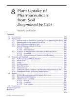
FIGURE 3.1
Subsurface zone of influence for SAT basin.
RI basin
Original water table
Profile
Unsaturated zone
of percolation
Water table
DK804X_C003.fm Page 47 Friday, July 1, 2005 3:26 PM
© 2006 by Taylor & Francis Group, LLC
48
Natural Wastewater Treatment Systems
influence for a rapid infiltration basin system or a treatment pond where significant
seepage is allowed. It is frequently necessary to determine the concentration of
a pollutant in the groundwater plume at a selected distance downgradient of the
source. Alternatively, it may be desired to determine the distance at which a given
concentration will occur at a given time or the time at which a given concentration
will reach a particular point. Figure 3.2 is a nomograph that can be used to
estimate these factors on the centerline of the downgradient plume (USEPA,
1985). The dispersion and retardation factors discussed above are included in the
solution. Data required for use of the nomograph include:
• Aquifer thickness, z (m)
• Porosity, n (%, as a decimal)
• Seepage velocity, v (m/d)
• Dispersivity factors a
x
and a
y
(m)
• Retardation factor R
d
for the contaminant of concern
•Volumetric water flow rate, Q (m
3
/d)
• Pollutant concentration at the source, C
0
(mg/L)
• Background concentration in groundwater, C
b
(mg/L)
•Mass flow rate of contaminant QC
0
(kg/d)
FIGURE 3.2 Nomograph for estimating pollutant travel.
DK804X_C003.fm Page 48 Friday, July 1, 2005 3:26 PM
© 2006 by Taylor & Francis Group, LLC
Basic Process Responses and Interactions 49
Use of the nomograph requires calculation of three scale factors:
(3.7)
(3.8)
(3.9)
The procedure is best illustrated with an example.
Example 3.1
Determine the nitrate concentration in the centerline of the plume, 600 m down-
gradient of a rapid infiltration system, 2 years after system startup. Data: aquifer
thickness = 5 m; porosity = 0.35; seepage velocity = 0.45 m/d; dispersivity, a
x
=
32 m, a
y
= 6 m; volumetric flow rate = 90 m
3
/d; nitrate concentration in percolate
= 20 mg/L; and nitrate concentration in background groundwater = 4 mg/L.
Solution
1. The downgradient volumetric flow rate combines the natural back-
ground flow plus the additional water introduced by the SAT system.
To be conservative, assume for this calculation that the total nitrate at
the origin of the plume is equal to the specified 20 mg/L. The residual
concentration determined with the nomograph is then added to the 4-
mg/L background concentration to determine the total downgradient
concentration at the point of concern. Experience has shown that nitrate
tends to be a conservative substance when the percolate has passed the
active root zone in the soil, so for this case assume that the retardation
factor R
d
is equal to 1.
2. Determine the dispersion coefficients:
D
x
= (a
x
)(v) = (32)(0.45) = 14.4 m
2
/d
D
y
= (a
y
)(v) = (6)(0.45) = 2.7 m
2
/d
3. Calculate the scale factors:
X
D
= D
x
/v = 14.4/0.45 = 32 m
t
D
= R
d
(D
x
)/(v)
2
= 1(14.4)/(0.45)
2
Q
D
= (16.02)(n)(z)[(D
x
)(D
y
)]
1/2
= (16.02)(0.35)(5)[(14.4)(2.7)]
1/2
= 174.8 kg/d
X
D
v
D
x
=
t
RD
v
D
d
x
=
()()
()
2
QnzDD
Dxy
=
()
()
[]
(.)()( )16 02
12
DK804X_C003.fm Page 49 Friday, July 1, 2005 3:26 PM
© 2006 by Taylor & Francis Group, LLC
50 Natural Wastewater Treatment Systems
4. Determine the mass flow rate of the contaminant:
(Q)(C
0
) = (90 m
3
/d)(20 mg/L)/(1000 g/kg) = 1.8 kg/d
5. Determine the entry parameters for the nomograph:
6. Enter the nomograph on the x/x
D
axis with the value of 18.8, draw a
vertical line to intersect with the t/t
D
curve = 10. From that point,
project a line horizontally to the A–A axis. Locate the calculated value
0.01 on the B–B axis and connect this with the previously determined
point on the A–A axis. Extend this line to the C–C axis and read the
concentration of concern, which is about 0.4 mg/L.
7. After 2 years, the nitrate concentration at a point 600 m downgradient
is the sum of the nomograph value and the background concentration,
or 4.4 mg/L.
Calculations must be repeated for each contaminant using the appropriate retar-
dation factor. The nomograph can also be used to estimate the distance at which
a given concentration will occur in a given time. The upper line on the figure is
the “steady-state” curve for very long time periods and, as shown in Example
3.2, can be used to evaluate conditions when equilibrium is reached.
Example 3.2
Using the data in Example 3.1, determine the distance downgradient where the
groundwater in the plume will satisfy the U.S. Environmental Protection Agency
(EPA) limits for nitrate in drinking-water supplies (10 mg/L).
Solution
1. Assuming a 4-mg/L background value, the plume concentration at the
point of concern could be as much as 6 mg/L. Locate 6 mg/L on the
C–C axis.
2. Connect the point on the C–C axis with the value 0.01 on the B–B axis
(as determined in Example 3.1). Extend this line to the A–A axis.
Project a horizontal line from this point to intersect the steady-state
line. Project a vertical line downward to the x/x
D
axis and read the
value x/x
D
= 60.
3. Calculate distance x using the previously determined value for x
D
:
x = (x
D
)(60) = (32)(60) = 1920 m
x
x
t
t
t
t
QC
Q
D
DD
D
==
== =
==
600
32
18 8
2 365
71
10 3 10
18
174 8
001
0
.
()( )
.
.
.
.
use curve
DK804X_C003.fm Page 50 Friday, July 1, 2005 3:26 PM
© 2006 by Taylor & Francis Group, LLC
Basic Process Responses and Interactions 51
3.1.3 GROUNDWATER MOUNDING
Groundwater mounding is illustrated schematically in Figure 3.1. The percolate
flow in the unsaturated zone is essentially vertical and controlled by K
v
. If a
groundwater table, impeding layer, or barrier exists at depth, a horizontal com-
ponent is introduced and flow is controlled by a combination of K
v
and K
h
within
the groundwater mound. At the margins of the mound and beyond, the flow is
typically lateral, and K
h
controls.
The capability for lateral flow away from the source will determine the extent
of mounding that will occur. The zone available for lateral flow includes the
underground aquifer plus whatever additional elevation is considered acceptable
for the particular project design. Excessive mounding will inhibit infiltration in
a SAT system. As a result, the capillary fringe above the groundwater mound
should never be closer than about 0.6 m (2 ft) to the infiltration surfaces in soil
aquifer treatment (SAT) basins. This will correspond to a water table depth of
about 1 to 2 m (3 to 7 ft), depending on the soil texture.
In many cases, the percolate or plume from a SAT system will emerge as
base flow in adjacent surface waters, so it may be necessary to estimate the
position of the groundwater table between the source and the point of emergence.
Such an analysis will reveal if seeps or springs are likely to develop in the
intervening terrain. In addition, some regulatory agencies require a specific res-
idence time in the soil to protect adjacent surface waters, so it may be necessary
to calculate the travel time from the source to the expected point of emergence.
Equation 3.10 can be used to estimate the saturated thickness of the water table
at any point downgradient of the source (USEPA, 1984). Typically, the calculation
is repeated for a number of locations, and the results are converted to an elevation
and plotted on maps and profiles to identify potential problem areas:
(3.10)
where
h=Saturated thickness of the unconfined aquifer at the point of concern
(ft; m).
h
0
= Saturated thickness of the unconfined aquifer at the source (ft; m).
d=Lateral distance from the source to the point of concern (ft; m).
K
h
= Effective horizontal permeability of the soil system, mid (ft/d).
Q
i
= Lateral discharge from the unconfined aquifer system per unit width of
the flow system (ft
3
/d·ft; m
3
/d·m):
(3.11)
hh
Qd
K
i
h
=
()
−
()
()
()
0
2
12
2
Q
K
d
hh
i
h
i
i
=−
()
2
0
22
DK804X_C003.fm Page 51 Friday, July 1, 2005 3:26 PM
© 2006 by Taylor & Francis Group, LLC
52 Natural Wastewater Treatment Systems
where
d
i
= Distance to the seepage face or outlet point (ft; m).
h
i
= Saturated thickness of the unconfined aquifer at the outlet point (ft; m).
The travel time for lateral flow is a function of the hydraulic gradient, the distance
traveled, the K
h
, and the porosity of the soil as defined by Equation 3.12:
(3.12)
where
t
D
= Travel time for lateral flow from source to the point of emergence in
surface waters (ft; m).
K
h
=Effective horizontal permeability of the soil system (ft/d; m/d).
h
0
, h
i
= Saturated thickness of the unconfined aquifer at the source and the
outlet point, respectively (ft; m).
d
i
= Distance to the seepage face or outlet point (ft; m).
n = Porosity, as a decimal fraction.
A simplified graphical method for determining groundwater mounding uses
the procedure developed by Glover
(1961) and summarized by Bianchi and Muckel
(1970). The method is valid for square or rectangular basins that lie above level,
fairly thick, homogeneous aquifers of assumed infinite extent; however, the behav-
ior of circular basins can be adequately approximated by assuming a square of
equal area. When groundwater mounding becomes a critical project issue, further
analysis using the Hantush method (Bauman, 1965) is recommended. Further
complications arise with sloped water tables or impeding subsurface layers that
induce “perched” mounds or due to the presence of a nearby outlet point. Refer-
ences by Brock (1976), Kahn and Kirkham (1976), and USEPA (1981) are sug-
gested for these conditions. The simplified method involves the graphical deter-
mination of several factors from Figure 3.3, Figure 3.4, Figure 3.5, or Figure 3.6,
depending on whether the basin is square or rectangular.
It is necessary to calculate the values of W/(4at)
0.5
and R
t
as defined in
Equations 3.13 to 3.15:
(3.13)
where W is the width of the recharge basin (ft; m), and
(3.14)
t
nd
Kh h
D
i
h
i
=
()
()
−
()
()
2
0
W
t()()()4
12
α
[]
= dimensionless scale factor
α=
()()
Kh
Y
h
s
0
DK804X_C003.fm Page 52 Friday, July 1, 2005 3:26 PM
© 2006 by Taylor & Francis Group, LLC
Basic Process Responses and Interactions 53
where
K
h
=Effective horizontal permeability of the aquifer (ft/d; m/d).
h
0
= Original saturated thickness of the aquifer beneath the center of the
recharge area (ft; m).
Y
s
= Specific yield of the soil (use Figure 2.5 or 2.6 to determine) (ft
3
/ft
3
;
m
3
/m
3
).
FIGURE 3.3 Groundwater mounding curve for center of a square recharge basin.
FIGURE 3.4 Groundwater mounding curves for center of a rectangle recharge area with
different ratios of length (L) to width (W).
W
4α t
h
m
Rt
1.0
0.8
0.6
0.4
0.2
0
0 1.0 2.0 3.0
DK804X_C003.fm Page 53 Friday, July 1, 2005 3:26 PM
© 2006 by Taylor & Francis Group, LLC
54 Natural Wastewater Treatment Systems
(R)(t) = scale factor (ft; m) (3.15)
where
R =(I)/(Y
s
) (ft/d; m/d), where I is the infiltration rate or volume of water
infiltrated per unit area of soil surface (ft
3
/ft
2
·d; m
3
/m
2
/d).
t = Period of infiltration, d.
Enter either Figure 3.3 or 3.4 with the calculated value of W/(4(αt)
1/2
to determine
the value for the ratio h
m
/(R)(t), where h
m
is the rise at the center of the mound.
Use the previously calculated value for (R)(t) to solve for h
m
. Figure 3.5 (for
square areas) and Figure 3.6 (for rectangular areas, where L = 2W) can be used
FIGURE 3.5 Rise and horizontal spread of a groundwater mound below a square recharge
area.
DK804X_C003.fm Page 54 Friday, July 1, 2005 3:26 PM
© 2006 by Taylor & Francis Group, LLC
Basic Process Responses and Interactions 55
to estimate the depth of the mound at various distances from the center of the
recharge area. The procedures involved are best illustrated with a design example.
Example 3.3
Determine the height and horizontal spread of a groundwater mound beneath a
circular SAT basin 30 m in diameter. The original aquifer thickness is 4 m, and
K
h
as determined in the field is 1.25 m/d. The top of the original groundwater
table is 6 m below the design infiltration surface of the constructed basin. The
design infiltration rate will be 0.3 m/d and the wastewater application period will
be 3 days in every cycle (3 days of flooding, 10 days for percolation and drying;
see Chapter 8 for details).
FIGURE 3.6 Rise and horizontal spread of a groudwater mound below a rectangular
recharge area with a length equal to twice its width.
DK804X_C003.fm Page 55 Friday, July 1, 2005 3:26 PM
© 2006 by Taylor & Francis Group, LLC
56 Natural Wastewater Treatment Systems
Solution
1. Determine the size of an equivalent area square basin:
Then the width (W) of an equivalent square basin is (706.5)
1/2
= 26.5 m.
2. Use Figure 2.5 to determine specific yield (Y
s
):
K
h
= 1.25 m/d = 5.21 cm/hr
Y
s
= 0.14
3. Determine the scale factors:
4. Use Figure 3.3 to determine the factor h
m
/(R)(t):
h
m
= (0.68)(R)(t) = (0.68)(2)(3) = 4.08 m
5. The original groundwater table is 6 m below the infiltration surface.
The calculated rise of 4.08 m would bring the top of the mound within
2 m of the basin infiltration surface. As discussed previously, this is
just adequate to maintain design infiltration rates. The design might
consider a shorter (say, 2-day) flooding period, as discussed in Chapter
8, to reduce the potential for mounding somewhat.
6. Use Figure 3.5 to determine the lateral spread of the mound. Use the
curve for W/(4(αt)
1/2
with the previously calculated value of 1.28, enter
the graph with selected values of x/W (where x is the lateral distance
of concern), and read values of h
m
/(R)(t). Find the depth to the top of
the mound 10 m from the centerline of basin:
x/W = 10/26.5 = 0.377
A
D
==
(. )( )
.
314
4
706 5
2
m
α
α
=
()()
==
()
=
[]
=
==
==
Kh
Y
W
t
R
Rt
h
s
0
12 12
125 4
014
35 7
4
26 5
43573
128
03
014
2
23 6
(. )()
.
.
.
()( .)( )
.
.
.
()() ()()
md
m/d
m
2
h
Rt
m
()()
.= 068
DK804X_C003.fm Page 56 Friday, July 1, 2005 3:26 PM
© 2006 by Taylor & Francis Group, LLC
Basic Process Responses and Interactions 57
Enter the x/W axis with this value, project up to W/(4αt)l
1/2
= 1.28,
then read 0.58 on the h
m
/(R)(t) axis:
h
m
= (0.58)(2)(3) = 3.48 m
The depth to the mound at the 10-m point is 6 m – 3.48 m = 2.52 m.
Similarly, at x = 13 m, the depth to the mound is 3.72 m, and at x =
26 m the depth to the mound is 5.6 m. This indicates that the water
level is almost back to the normal groundwater level at a lateral distance
about equal to two times the basin width. Changing the application
schedule to 2 days instead of 3 would reduce the peak water level to
about 3 m below the infiltration surface of the basin.
The procedure demonstrated in Example 3.3 is valid for a single basin;
however, as described in Chapter 8, SAT systems typically include multiple basins
that are loaded sequentially, and it is not appropriate to do the mounding calcu-
lation by assuming that the entire treatment area is uniformly loaded at the design
hydraulic loading rate. In many situations, this will result in the erroneous con-
clusion that mounding will interfere with system operation.
It is necessary first to calculate the rise in the mound beneath a single basin
during the flooding period. When hydraulic loading stops at time t, a uniform
hypothetical discharge is assumed starting at t and continuing for the balance of
the rest period. The algebraic sum of these two mound heights then approximates
the mound shape just prior to the start of the next flooding period. Because
adjacent basins may be flooded during this same period, it is also necessary to
determine the lateral extent of their mounds and then add any increment from
these sources to determine the total mound height beneath the basin of concern.
The procedure is illustrated by Example 3.4.
Example 3.4
Determine the groundwater mound height beneath a SAT basin at the end of the
operational cycle. Assume that the basin is square, 26.5 m on a side, and is one
in a set of four arranged in a row (26.5 m wide by 106 m long). Assume the
same site conditions as in Example 3.3. Also assume that flooding commences
in one of the adjacent basins as soon as the rest period for the basin of concern
begins. The operational cycle is 2 days flood, 12 days rest.
Solution
1. The maximum rise beneath the basin of concern would be the same
as calculated in Example 3.3 with 2-day flooding: h
m
= 3.00 m.
2. The influence from the next 2 days of flooding in the adjacent basin
would be about equal to the mound rise at the 26-m point calculated
in Example 3.3, or 0.4 m. All the other basins are beyond the zone of
influence, so the maximum potential rise beneath the basin of concern
is (3.00) + (0.4) = 3.4 m. The mound will actually not rise that high,
because during the 2 days the adjacent basin is being flooded the first
DK804X_C003.fm Page 57 Friday, July 1, 2005 3:26 PM
© 2006 by Taylor & Francis Group, LLC
58 Natural Wastewater Treatment Systems
basin is draining. However, for the purposes of this calculation, assume
that the mound will rise the entire 3.4 m above the static groundwater
table.
3. The R value for this “uniform” discharge will be the same as that
calculated in Example 3.2, but t will now be 12 days: (R)(t) = (2)(12)
= 24 m/d.
4. Calculate a new W/(4αt)
1/2
, as the “new” time is 12 days:
W/(4αt)
1
/
2
= 26.5/[(4)(35.7)(12)]
1/2
= 0.62
5. Use Figure 3.3 to determine “h
m
”/(R)(t) = 0.30: “h
m
” = (24)(0.3) = 7.2
m. This is the hypothetical drop in the mound that could occur during
the 10-day rest period; however, the water level cannot actually drop
below the static groundwater table, so the maximum possible drop
would be 3.4 m. This indicates that the mound would dissipate well
before the start of the next flooding cycle. Assuming that the drop
occurs at a uniform rate of 0.72 m/d, the 3.4-m mound will be gone
in 4.7 days.
In cases where the groundwater mounding analysis indicates potential inter-
ference with system operation, several corrective options are available. As
described in Chapter 8, the flooding and drying cycles can be adjusted or the
layout of the basin sets rearranged into a configuration with less inter-basin
interference. The final option is to underdrain the site to control mound develop-
ment physically.
Underdrainage may also be required to control shallow or seasonal natural
groundwater levels when they might interfere with the operation of either a land
or aquatic treatment system. Underdrains are also sometimes used to recover the
treated water beneath land treatment systems for beneficial use or discharge
elsewhere.
3.1.4 UNDERDRAINAGE
In order to be effective, drainage or water recovery elements must either be at or
within the natural groundwater table or just above some other flow barrier. When
drains can be installed at depths of 5 m (16 ft) or less, underdrains are more
effective and less costly than a series of wells. It is possible using modern
techniques to install semiflexible plastic drain pipe enclosed in a geotextile
membrane by means of a single machine that cuts and then closes the trench.
In some cases, underdrains are a project necessity to control a shallow ground-
water table so the site can be developed for wastewater treatment. Such drains,
if effective for groundwater control, will also collect the treated percolate from
a land treatment operation. The collected water must be discharged, so the use
of underdrains in this case converts the project to a surface-water discharge system
unless the water is otherwise used or disposed of. In a few situations, drains have
been installed to control a seasonally high water table. This type of system may
DK804X_C003.fm Page 58 Friday, July 1, 2005 3:26 PM
© 2006 by Taylor & Francis Group, LLC
Basic Process Responses and Interactions 59
require a surface-water discharge permit during the period of high groundwater
but will function as a nondischarging system for the balance of the year.
The drainage design consists of selecting the depth and spacing for placement
of the drain pipes or tiles. In the typical case, drains may be at a depth of 1 to 3
m (3 to 10 ft) and spaced 60 m (200 ft) or more apart. In sandy soils, the spacing
may approach 150 m (500 ft). The closer spacings provide better water control,
but the costs increase significantly.
The Hooghoudt method (Luthin, 1973) is the most commonly used method
for calculating drain spacing. The procedure assumes that the soil is homoge-
neous, that the drains are spaced evenly apart, that Darcy’s law is applicable, that
the hydraulic gradient at any point is equal to the slope of the water table above
that point, and that a barrier of some type underlies the drain. Figure 3.7 defines
the necessary parameters for drain design, and Equation 3.16 can be used for
design:
(3.16)
where
S = Drain spacing (ft; m).
K
h
= Horizontal permeability of the soil (ft/d; m/d).
h
m
= Height of groundwater mound above the drains (ft; m).
L
w
= Annual wastewater loading rate expressed as a daily rate (ft/d; m/d).
P =Average annual precipitation expressed as a daily rate (ft/d; m/d).
d = Distance from drain to barrier (ft; m).
FIGURE 3.7 Definition sketch for calculation of drain spacing.
S
Kh
LP
dh
h
m
w
m
=
()()
+
+
()
()
/
4
2
12
DK804X_C003.fm Page 59 Friday, July 1, 2005 3:26 PM
© 2006 by Taylor & Francis Group, LLC
60 Natural Wastewater Treatment Systems
The position of the top of the mound between the drains is established by design
or regulatory requirements for a particular project. SAT systems, for example,
require a few meters of unsaturated soil above the mound in order to maintain
the design infiltration rate; SR systems also require an unsaturated zone to provide
desirable conditions for the surface vegetation. See Chapter 8 for further detail.
Procedures and criteria for more complex drainage situations can be found in
USDI (1978) and Van Schifgaarde (1974).
3.2 BIODEGRADABLE ORGANICS
Biodegradable organic contaminants, in either dissolved or suspended form, are
characterized by the biochemical oxygen demand (BOD) of the waste. Table 1.1,
Table 1.2, and Table 1.3 present typical BOD removal expectations for the natural
treatment systems described in this book.
3.2.1 REMOVAL OF BOD
As explained in Chapters 4 through 7, the biological oxygen demand (BOD)
loading can be the limiting design factor for pond, aquatic, and wetland systems.
The basis for these limits is the maintenance of aerobic conditions within the
upper water column in the unit and the resulting control of odors. The natural
sources of dissolved oxygen (DO) in these systems are surface reaeration and
photosynthetic oxygenation. Surface reaeration can be significant under windy
conditions or if surface turbulence is created by mechanical means. Observation
has shown that the DO in unaerated wastewater ponds varies almost directly with
the level of photosynthetic activity, being low at night and early morning, and
rising to a peak in the early afternoon. The phytosynthetic responses of algae are
controlled by the presence of light, the temperature of the liquid, and the avail-
ability of nutrients and other growth factors.
Because algae are difficult to remove and can represent an unacceptable level
of suspended solids in the effluent, some pond and aquaculture processes utilize
mechanical aeration as the oxygen source. In partially mixed aerated ponds, the
increased depth of the pond and the partial mixing of the somewhat turbid contents
limit the development of algae as compared to a facultative pond. Most wetland
systems (Chapters 6 and 7) restrict algae growth, as the vegetation limits the
penetration of light to the water column.
Emergent plant species used in wetlands treatment have the unique capability
to transmit oxygen from the leaf to the plant root. These plants do not themselves
remove the BOD directly; rather, they serve as hosts for a variety of attached
growth organisms, and it is this microbial activity that is primarily responsible
for the organic decomposition. The stems, stalks, roots, and rhizomes of the
emergent varieties provide the necessary surfaces. This dependence requires a
relatively shallow reactor and a relatively low flow velocity to ensure optimum
contact opportunities between the wastewater and the attached microbial growth.
DK804X_C003.fm Page 60 Friday, July 1, 2005 3:26 PM
© 2006 by Taylor & Francis Group, LLC
Basic Process Responses and Interactions 61
Wu et al. (2001) reported that little oxygen escaped from the roots of Typha
latifolia in a constructed wetland, and in this system the major pathway of oxygen
was atmospheric diffusion. These results were reported to be species specific,
and other results for Spartina pectinata by Wu et al. (2000) indicate that the
potential oxygen release could be 15 times that for T. latifolia. They also con-
cluded that the amount of oxygen transferred to the wetlands through macrophyte
roots and atmospheric diffusion were relatively small compared to the amount of
oxygen required to oxidize ammonia.
The BOD of the wastewater or sludge is seldom the limiting design factor
for the land treatment processes described in Chapter 8. Other factors, such as
nitrogen, metals, toxics, or the hydraulic capacity of the soils, control the design
so the system almost never approaches the upper limits for successful biodegra-
dation of organics. Table 3.2 presents typical organic loadings for natural treat-
ment systems.
3.2.2 REMOVAL OF SUSPENDED SOLIDS
The suspended solids content of wastewater is not usually a limiting factor for
design, but the improper management of solids within the system can result in
process failure. One critical concern for both aquatic and terrestrial systems is
the attainment of proper distribution of solids within the treatment reactor. The
use of inlet diffusers in ponds, step feed (multiple inlets) in wetland channels,
and higher pressure sprinklers in industrial overland-flow systems is intended to
TABLE 3.2
Typical Organic Loading Rates for Natural
Treatment Systems
Process
Organic Loading
(kg/ha/d)
Oxidation pond 40–120
Facultative pond 22–67
Aerated partial-mix pond 50–200
Hyacinth pond 20–50
Constructed wetland 100
Slow rate land treatment 45–450
Rapid infiltration land treatment 130–890
Overland flow land treatment 35–100
Land application of municipal sludge 27–930
a
a
These values were determined by dividing the annual rate
by 365 days.
DK804X_C003.fm Page 61 Friday, July 1, 2005 3:26 PM
© 2006 by Taylor & Francis Group, LLC
62 Natural Wastewater Treatment Systems
achieve a more uniform distribution of solids and avoid anaerobic conditions at
the head of the process. The removal of suspended solids in pond systems depends
primarily on gravity sedimentation, and, as mentioned previously, algae can be
a concern in some situations. Sedimentation and entrapment in the microbial
growths are both contributing factors in wetland and overland-flow processes.
Filtration in the soil matrix is the principal mechanism for SR and SAT systems.
Removal expectations for the various processes are listed in Table 1.1, Table 1.2,
and Table 1.3. Removal will typically exceed secondary treatment levels, except
for some of the pond systems that contain algal solids in their effluents.
3.3 ORGANIC PRIORITY POLLUTANTS
Many organic priority pollutants are resistant to biological decomposition. Some
are almost totally resistant and may persist in the environment for considerable
periods of time; others are toxic or hazardous and require special management.
3.3.1 REMOVAL METHODS
Volatilization, adsorption, and then biodegradation are the principal methods for
removing trace organics in natural treatment systems. Volatilization can occur at
the water surface of ponds, wetlands, and SAT basins; in the water droplets from
sprinklers used in land treatment; from the liquid films in overland-flow systems;
and from the exposed surfaces of sludge. Adsorption occurs primarily on the
organic matter in the treatment system that is in contact with the waste. In many
cases, microbial activity then degrades the adsorbed materials.
3.3.1.1 Volatilization
The loss of volatile organics from a water surface can be described using first-
order kinetics, because it is assumed that the concentration in the atmosphere
above the water surface is essentially zero. Equation 3.17 is the basic kinetic
equation, and Equation 3.18 can be used to determine the “half-life” of the
contaminant of concern (see Chapter 9 for further discussion of the half-life
concept and its application to sludge organics):
(3.17)
where
C
t
= Concentration at time t (mg/L or g/L).
C
0
= Initial concentration at t = 0 (mg/L or g/L).
k
vol
=Volatilization mass transfer coefficient (cm/hr) = (k)(y).
k =Overall rate coefficient (hr
–1
).
y = Depth of liquid (cm).
C
C
e
t
kty
vol
0
=
−
()
()( )
DK804X_C003.fm Page 62 Friday, July 1, 2005 3:26 PM
© 2006 by Taylor & Francis Group, LLC
Basic Process Responses and Interactions 63
(3.18)
where t
1/2
is the time when concentration C
t
= (1/2)(C
0
) (hr), and the other terms
are as defined previously.
The volatilization mass transfer coefficient is a function of the molecular
weight of the contaminant and the air/water partition coefficient as defined by
the Henry’s law constant, as shown by Equation 3.19:
(3.19)
where
k
vol
=Volatilization coefficient (hr
–1
).
H = Henry’s law constant (10
5
atm·m
3
·mol
–1
).
M =Molecular weight of contaminant of concern (g/mol).
The coefficients B
1
and B
2
are specific to the physical system of concern. Dilling
(1977) determined values for a variety of volatile chlorinated hydrocarbons at a
well-mixed water surface:
B
1
= 2.211, B
2
= 0.01042
Jenkins et al. (1985) experimentally determined values for a number of volatile
organics on an overland flow slope:
B
1
= 0.2563, B
2
= (5.86)(10
–4
)
The coefficients for the overland-flow case are much lower because the flow of
liquid down the slope is nonturbulent and may be considered almost laminar flow
(Reynolds number = 100 – 400). The average depth of flowing liquid on this
slope was about 1.2 cm (Jenkins et al., 1985).
Using a variation of Equation 3.19, Parker and Jenkins
(1986) determined
volatilization losses from the droplets at a low-pressure, large-droplet wastewater
sprinkler. In this case, the y term in the equation is equal to the average droplet
radius; as a result, their coefficients are valid only for the particular sprinkler
system used. The approach is valid, however, and can be used for other sprinklers
and operating pressures. Equation 3.20 was developed by Parker and Jenkins for
the organic compounds listed in Table 3.3:
(3.20)
t
y
k
vol
12
0 693
/
(. )()
=
k
B
y
H
BHM
vol
=
+
()
1
2
12
()
/
ln ( . ) .
C
C
k
t
vol
0
4
4 535 11 02 10=
′
+
()
[]
−
DK804X_C003.fm Page 63 Friday, July 1, 2005 3:26 PM
© 2006 by Taylor & Francis Group, LLC
64 Natural Wastewater Treatment Systems
Volatile organics can also be removed by aeration in pond systems. Clark et al.
(1984a) developed Equation 3.21 to determine the amount of air required to strip
a given quantity of volatile organics from water via aeration:
(3.21)
where
(A/W)=Air-to-water ratio.
S = Saturated condition of the compound of concern equal to 0, for
unsaturated organics; 1, for saturated compounds).
V =Vapor pressure (mmHg).
M =Molecular weight (g/mol).
s = Solubility of organic compound (mg/L).
The values in Table 3.4 can be used in Equation 3.21 to calculate the air-to-water
ratio required for some typical volatile organics.
TABLE 3.3
Volatile Organic Removal
by Wastewater Sprinkling
Substance
Calculated k
vol
′′
′′
for
Equation 3.20 (cm/min)
Chloroform 0.188
Benzene 0.236
Toluene 0.220
Chlorobenzene 0.190
Bromoform 0.0987
m-Dichlorobenzene 0.175
Pentane 0.260
Hexane 0.239
Nitrobenzene 0.0136
m-Nitrotoluene 0.0322
PCB 1242 0.0734
Naphthalene 0.114
Phenanthrene 0.0218
Source: Parker, L.V. and Jenkins, T.F., Water Res.,
20(11), 1417–1426, 1986. With permission.
A
W
C
C
SV M
t
s
=−
−−
(.) ()() () (.)
.
.
76 4 1 0 33
0
12 44
037 045 018
DK804X_C003.fm Page 64 Friday, July 1, 2005 3:26 PM
© 2006 by Taylor & Francis Group, LLC
Basic Process Responses and Interactions 65
3.3.1.2 Adsorption
Sorption of trace organics to the organic matter present in the treatment system
is thought to be the primary physicochemical mechanism of removal (USEPA,
1982a). The concentration of the trace organic that is sorbed relative to that in
solution is defined by a partition coefficient K
p
, which is related to the solubility
of the chemical. This value can be estimated if the octanol–water partition coef-
ficient (K
ow
) and the percentage of organic carbon in the system are defined, as
shown by Equation 3.22:
log K
oc
= (1.00)(log K
ow
) – 0.21 (3.22)
where
K
oc
= Sorption coefficient expressed on an organic carbon basis equal to
K
sorb
/O
c
.
K
sorb
= Sorption mass transfer coefficient (cm/hr).
O
c
= Percentage of organic carbon present in the system.
K
ow
= Octanol–water partition coefficient.
Hutchins et al. (1985) presented other correlations and a detailed discussion of
sorption in soil systems.
Jenkins et al. (1985) determined that sorption of trace organics on an overland-
flow slope could be described with first-order kinetics with the rate constant
defined by Equation 3.23:
TABLE 3.4
Properties of Selected Volatile Organics
for Equation 3.21
Chemical MS s
Trichloroethylene 132 1000 0
1,1,1-Trichloroethane 133 5000 1
Tetrachloroethlyene 166 145 0
Carbon tetrachloride 154 800 1
cis-1,2-Dichloroethylene 97 3500 0
1,2-Dichloroethane 99 8700 1
1,1-Dichloroethylene 97 40 0
Source: Love, O.T. et al., Treatment of Volatile Organic Chemi-
cals in Drinking Water, EPA 600/8-83-019, U.S. Environmental
Protection Agency, Municipal Engineering Research Laboratory,
Cincinnati, OH, 1983.
DK804X_C003.fm Page 65 Friday, July 1, 2005 3:26 PM
© 2006 by Taylor & Francis Group, LLC
66 Natural Wastewater Treatment Systems
(3.23)
where
k
sorb
= Sorption coefficient (hr
–1
).
B
3
= Coefficient specific to the treatment system, equal to 0.7309 for the
overland-flow system studied.
y = Depth of water on the overland-flow slope (1.2 cm).
K
ow
= Octanol–water partition coefficient.
B
4
= Coefficient specific to the treatment system = 170.8 for the overland-
flow system studied.
M =Molecular weight of the organic chemical (g/mol).
In many cases, the removal of trace organics is due to a combination of sorption
and volatilization. The overall process rate constant (k
sv
) is then the sum of the
coefficients defined with Equations 3.19 and 3.23, and the combined removal is
described by Equation 3.24:
(3.24)
where
C
t
= Concentration at time t (mg/L or µg/L).
C
0
= Initial concentration at t equal to 0 (mg/L or µg/L).
k
sv
=Overall rate constant for combined volatilization and sorption equal to
k
vol
+ k
sorb
.
Table 3.5 presents the physical characteristics of a number of volatile organics
for use in the equations presented above for volatilization and sorption.
Example 3.5
Determine the removal of toluene in an overland-flow system. Assume a 30-m-
long terrace; hydraulic loading of 0.4 m
3
·hr·m (see Chapter 8 for discussion);
mean residence time on slope of 90 min; wastewater application with a low-
pressure, large-droplet sprinkler; physical characteristics for toluene (Table 3.5)
of K
w
= 490, H = 515, M = 92; depth of flowing water on the terrace = 1.5 cm;
concentration of toluene in applied wastewater = 70 µg/L.
Solution
1. Use Equation 3.20 to estimate volatilization losses during sprinkling:
k
B
y
K
BK M
sorb
ow
ow
=
+
()
3
4
12
()
/
C
C
e
tkt
sv
0
=
()
()
ln . . ( )
.
(. )(. ) . )
C
C
k
Ce
t
vol
t
0
4
4 535 0 220 0 00112
4 535 11 02 10
70 25 6
=
′
+
[]
=
[]
=
−
−+
µg/L
DK804X_C003.fm Page 66 Friday, July 1, 2005 3:26 PM
© 2006 by Taylor & Francis Group, LLC
Basic Process Responses and Interactions 67
2. Use Equation 3.19 to determine the volatilization coefficient during
flow on the overland-flow terrace:
3. Use Equation 3.23 to determine the sorption coefficient during flow
on the overland-flow terrace:
TABLE 3.5
Physical Characteristics for Selected Organic Chemicals
Substance K
ow
a
H
b
Vapor
Pressure
c
M
d
Chloroform 93.3 314 194 119
Benzene 135 435 95.2 78
Toluene 490 515 28.4 92
Chlorobenzene 692 267 12 113
Bromoform 189 63 5.68 253
m-Dichlorobenzene 2.4 × 10
3
360 2.33 147
Pentane 1.7 × 10
3
125,000 520 72
Hexane 7.1 × 10
3
170,000 154 86
Nitrobenzene 70.8 1.9 0.23 123
m-Nitrotoluene 282 5.3 0.23 137
Diethylphthalate 162 0.056 7 × 10
–4
222
PCB 1242 3.8 × 10
5
30 4 × 10
–4
26
Naphthalene 2.3 ×10
3
36 8.28 × 10
–2
128
Phenanthrene 2.2 × 10
4
3.9 2.03 × 10
–4
178
2,4-Dinitrophenol 34.7 0.001 — 184
a
Octanol-water partition coefficient.
b
Henry’s law constant, 10
5
atm-m
3
/mol at 20°C and 1 atm.
c
At 25°C.
d
Molecular weight (g/mol).
k
B
y
H
BHM
k
vol
vol
=
+
()
=
+
=
=
−
1
2
12
412
0 2563
15
515
586 10 515 92
0 17087 0 1042
0 0178
()
.
.(.)()()()
(. )(. )
.
/
/
DK804X_C003.fm Page 67 Friday, July 1, 2005 3:26 PM
© 2006 by Taylor & Francis Group, LLC