Natural Wastewater Treatment Systems - Chapter 9 ppt
Bạn đang xem bản rút gọn của tài liệu. Xem và tải ngay bản đầy đủ của tài liệu tại đây (1.12 MB, 56 trang )
437
9
Sludge Management
and Treatment
Approximately 6.9 million ton of biosolids were generated in the United States
in 1998, and about 60% of it was used beneficially in land applications, com-
posting, and landfill cover. It is estimated that, by 2010, 8.2 million tons will be
generated, and 70% of the biosolids is expected to be used beneficially (USEPA,
1999). Recycling options are described in various documents (Crites and
Tchobanoglous, 1998; Crites et al., 2000; USEPA, 1994a, 1995a,c). Sludges are
a common by-product from all waste treatment systems, including some of the
natural processes described in previous chapters. Sludges are also produced by
water treatment operations and by many industrial and commercial activities. The
economics and safety of disposal or reuse options are strongly influenced by the
water content of the sludge and the degree of stabilization with respect to patho-
gens, organic content, metals content, and other contaminants. This chapter
describes several natural methods for sludge treatment and reuse. In-plant sludge
processing methods, such as thickening, digestion, and mechanical methods for
conditioning and dewatering, are not included in this text; instead, Grady et al.
(1999), ICE (2002), Metcalf & Eddy (2003), Reynolds and Richards (1996), and
USEPA (1979, 1982) are recommended for that purpose.
9.1 SLUDGE QUANTITY AND CHARACTERISTICS
The first step in the design of a treatment or disposal process is to determine the
amount of sludge that must be managed and its characteristics. Deriving a solids
mass balance for the treatment system under consideration can produce a reliable
estimate. The solids input and output for every component in the system must be
calculated. Typical values for solids concentrations from in-plant operations and
processes are reported in Table 9.1. Detailed procedures for conducting mass
balance calculations for wastewater treatment systems can be found in Grady et
al. (1999), Metcalf & Eddy (2003), Reynolds and Richards (1996), and USEPA
(1979). The characteristics of wastewater treatment sludges are strongly depen-
dent on the composition of the untreated wastewater and on the unit operations
in the treatment process. The values reported in Table 9.2 and Table 9.3 represent
typical conditions only and are not a suitable basis for a specific project design.
The sludge characteristics must be either measured or carefully estimated from
similar experience elsewhere to provide the data for final designs.
DK804X_C009.fm Page 437 Thursday, July 21, 2005 8:10 AM
© 2006 by Taylor & Francis Group, LLC
438
Natural Wastewater Treatment Systems
TABLE 9.1
Typical Solids Content from Treatment Operations
Treatment Operation
Percent
(%)
a
Typical Dry Solids
(kg/10
3
m
3
)
b
Primary Settling
Primary only 5 150
Primary and waste-activated sludge 1.5 45
Primary and trickling-filter sludge 5 150
Secondary Reactors
Activated sludge:
Pure oxygen 2.5 130
Extended aeration 1.5 100
Trickling filters 1.5 70
Chemical Plus Primary Sludge
High lime (>800 mg/L) 10 800
Low lime (<500 mg/L) 4 300
Iron salts 7.5 600
Thickeners
Gravity type:
Primary sludge 8 140
Primary and waste-activated sludge 4 70
Primary and trickling filter 5 90
Flotation 4 70
Digestion
Anaerobic:
Primary sludge 7 210
Primary and waste-activated sludge 3.5 105
Aerobic:
Primary and waste-activated sludge 2.5 80
a
Percent solids in liquid sludge.
b
kg/10
3
m
3
= dry solids/1000 m
3
liquid sludge.
Source:
Metcalf & Eddy,
Wastewater Engineering: Treatment, Disposal, and Reuse
, 3rd
ed., McGraw-Hill, New York, 1991. With permission.
DK804X_C009.fm Page 438 Thursday, July 21, 2005 8:10 AM
© 2006 by Taylor & Francis Group, LLC
Sludge Management and Treatment
439
TABLE 9.2
Typical Composition of Wastewater Sludges
Component
Untreated
Primary Digested
Total solids (TS; %) 5 10
Volatile solids (% of TS) 65 40
pH 6 7
Alkalinity (mg/L as CaCO
3
) 600 3000
Cellulose (% of TS) 10 10
Grease and fats (ether soluble; % of TS) 6–30 5–20
Protein (% of TS) 25 18
Silica (SiO
2
; % of TS) 15 10
Source:
Metcalf & Eddy,
Wastewater Engineering: Treatment, Disposal, and
Reuse
, 3rd ed., McGraw-Hill, New York, 1991. With permission.
TABLE 9.3
Nutrients and Metals in Typical Wastewater Sludges
Component Median Mean
Total nitrogen (%) 3.3 3.9
NH
4
+
(as N; %) 0.09 0.65
NO
3
–
(as N; %) 0.01 0.05
Phosphorus (%) 2.3 2.5
Potassium (%) 0.3 0.4
Mean Standard Deviation
Copper (mg/kg) 741 962
Zinc (mg/kg) 1200 1554
Nickel (mg/kg) 43 95
Lead (mg/kg) 134 198
Cadmium (mg/kg) 7 12
PCB-1248 (mg/kg) 0.08 1586
Source:
Data from USEPA (1983, 1990) and Whiting (1975).
DK804X_C009.fm Page 439 Thursday, July 21, 2005 8:10 AM
© 2006 by Taylor & Francis Group, LLC
440
Natural Wastewater Treatment Systems
9.1.1 S
LUDGES
FROM
N
ATURAL
T
REATMENT
S
YSTEMS
A significant advantage for the natural wastewater treatment systems described
in previous chapters is the minimal sludge production in comparison to mechan-
ical treatment processes. Any major quantities of sludge are typically the result
of preliminary treatments and not the natural process itself. The pond systems
described in Chapter 4 are an exception in that, depending on the climate, sludge
will accumulate at a gradual but significant rate, and its ultimate removal and
disposal must be given consideration during design. In colder climates, studies
have established that sludge accumulation proceeds at a faster rate, so removal
may be required more than once over the design life of the pond. The results of
investigations in Alaska and Utah
(Schneiter et al., 1984) on sludge accumulation
and composition in both facultative and partial-mix aerated lagoons are reported
in Table 9.4 and Table 9.5.
A comparison of the values in Table 9.4 and Table 9.5 with those in Table
9.2 and Table 9.3 indicates that the pond sludges are similar to untreated primary
sludges. The major difference is that the solids content, both total and volatile,
is higher for most pond sludges than for primary sludge, and the fecal coliforms
are significantly lower. This is reasonable in light of the very long detention time
in ponds as compared with primary clarifiers. The long detention time allows for
significant die-off of fecal coliforms and for some consolidation of the sludge
solids. All four of the lagoons described in Table 9.4 and Table 9.5 are assumed
to be located in cold climates. Pond systems in the southern half of the United
States might expect lower accumulation rates than those indicated in Table 9.4.
TABLE 9.4
Pond Sludge Accumulation Data Summary
Facultative Ponds
(Utah)
Aerated Ponds
(Alaska)
Parameter A B C D
Flow (m
3
/d) 37,850 694 681 284
Surface (m
2
) 384,188 14,940 13,117 2520
Bottom (m
2
) 345,000 11,200 8100 1500
Operated since last cleaning (yr) 13 9 5 8
Mean sludge depth (cm) 8.9 7.6 33.5 27.7
Total solids (g/L) 58.6 76.6 85.8 9.8
Volatile solids (g/L) 40.5 61.5 59.5 4.8
Wastewater, suspended solids (mg/L) 62 69 185 170
Source:
Schneiter, R.W. et al.,
Accumulation, Characterization and Stabilization of Sludges from
Cold Regions Lagoons
, CRREL Special Report 84-8, U.S. Army Cold Regions Research and
Engineering Laboratory, Hanover, NH, 1984. With permission.
DK804X_C009.fm Page 440 Thursday, July 21, 2005 8:10 AM
© 2006 by Taylor & Francis Group, LLC
Sludge Management and Treatment
441
9.1.2 S
LUDGES
FROM
D
RINKING
-W
ATER
T
REATMENT
Sludges occur in water treatment systems as a result of turbidity removal, soft-
ening, and filter backwash. The dry weight of sludge produced per day from
softening and turbidity removal operations can be calculated using Equation 9.1
(Lang et al., 1985):
S
= 84.4
Q
(2Ca + 2.6Mg + 0.44Al + 1.9Fe +
SS
+
A
x
) (9.1)
where
S
= Sludge solids (kg/d).
Q
= Design water treatment flow (m
3
/s).
Ca = Calcium hardness removed (as CaCO
3
; mg/L).
Mg = Magnesium hardness removed (as CaCO
3
; mg/L).
Al = Alum dose (as 17.1% Al
2
O
3
; mg/L).
Fe = Iron salts dose (as Fe; mg/L).
SS
=Raw-water suspended solids (mg/L).
A
x
= Additional chemicals (e.g., polymers, clay, activated carbon) (mg/L).
The major components of most of these sludges are due to the suspended solids
(SS) from the raw water and the coagulant and coagulant aids used in treatment.
TABLE 9.5
Composition of Pond Sludges
Facultative Ponds
(Utah)
Aerated Ponds
(Alaska)
Parameter A B C D
Total solids (%) 5.9 7.7 8.6 0.89
Total solids (mg/L) 586,000 766,600 85,800 9800
Volatile solids (%) 69.1 80.3 69.3 48.9
Total organic carbon (mg/L) 5513 6009 13,315 2651
pH 6.7 6.9 6.4 6.8
Fecal coliforms
([number/100 mL]
×
10
5
)
0.7 1 0.4 2.5
Total Kjeldahl nitrogen (mg(L) 1028 1037 1674 336
Total Kjeldahl nitrogen (% of TS) 1.75 1.35 1.95 3.43
Ammonia nitrogen (as N; mg/L) 72.6 68.6 93.2 44.1
Ammonia nitrogen (as N; % of TS) 0.12 0.09 0.11 0.45
Source:
Schneiter, R.W. et al.,
Accumulation, Characterization and Stabilization of Sludges
from Cold Regions Lagoons
, CRREL Special Report 84-8, U.S. Army Cold Regions Research
and Engineering Laboratory, Hanover, NH, 1984. With permission.
DK804X_C009.fm Page 441 Thursday, July 21, 2005 8:10 AM
© 2006 by Taylor & Francis Group, LLC
442
Natural Wastewater Treatment Systems
Sludges resulting from coagulation treatment are the most common and are
typically found at all municipal water treatment works. Typical characteristics of
these sludges are reported in Table 9.6.
9.2 STABILIZATION AND DEWATERING
Stabilization of wastewater sludges and dewatering of most all types of sludge
are necessary for economic, environmental, and health reasons. Transport of
sludge from the treatment plant to the point of disposal or reuse is a major factor
in the costs of sludge management. Table 9.7 presents the desirable sludge solids
content for the major disposal and reuse options. Sludge stabilization controls
offensive odors, lessens the possibility for further decomposition, and signifi-
cantly reduces pathogens. Typical pathogen contents in unstabilized and anaero-
bically digested sludges are compared in Table 3.10. Research on the use of
various fungal strains as a means to stabilize sludges has been conducted with
mixed results but may hold promise in some cases (Alam et al., 2004).
9.2.1 M
ETHODS
FOR
P
ATHOGEN
R
EDUCTION
The pathogen content of sludge is especially critical when the sludge is to be
used in agricultural operations or when public exposure is a concern. Four pro-
cesses to significantly reduce pathogens and seven processes to further reduce
pathogens are recognized by the U.S. Environmental Protection Agency (EPA),
as described by Bastian (1993), Crites et al. (2000), and USEPA (2003a).
TABLE 9.6
Characteristics of Water Treatment Sludges
Characteristic Range of Values
Volume (as percent of water treated) <1.0
Suspended solids concentration 0.1–1000 mg/L
Solids content 0.1–3.5%
Solids content after long-term settling 10–35%
Composition, alum sludge:
Hydrated aluminum oxide 15–40%
Other inorganic materials 70–35%
Organic materials 15–25%
Source:
Lang, L.E. et al.,
Procedures for Evaluating and Improving
Water Treatment Plant Processes at Fixed Army Facilities
, Report
of the U.S. Army Construction Engineering Research Laboratory,
Champaign, IL, 1985.
DK804X_C009.fm Page 442 Thursday, July 21, 2005 8:10 AM
© 2006 by Taylor & Francis Group, LLC
Sludge Management and Treatment
443
9.3 SLUDGE FREEZING
Freezing and then thawing a sludge will convert an undrainable jelly-like mass
into a granular material that will drain immediately upon thawing. This natural
process may offer a cost-effective method for dewatering.
9.3.1 E
FFECTS
OF
F
REEZING
Freeze–thawing will have the same effect on any type of sludge but is particularly
beneficial with chemical and biochemical sludges containing alum which are
extremely slow to drain naturally. Energy costs for artificial freeze–thawing are
prohibitive, so the concept must depend on natural freezing to be cost effective.
9.3.2 P
ROCESS
R
EQUIREMENTS
The design of a freeze dewatering system must be based on worst-case conditions
to ensure successful performance at all times. If sludge freezing is to be a reliable
expectation every year, the design must be based on the warmest winter during
the period of concern (typically 20 years or longer). The second critical factor is
the thickness of the sludge layer that will freeze within a reasonable period if
freeze–thaw cycles are a normal occurrence during the winter. A common mistake
with past attempts at sludge freezing has been to apply sludge in a single deep
layer. In many locations, a large single layer may never freeze completely to the
bottom, so only the upper portion goes through alternating freezing and thawing
cycles. It is absolutely essential that the entire mass of sludge be frozen completely
for the benefits to be realized; also, when the sludge has frozen and thawed, the
change is irreversible.
TABLE 9.7
Solids Content for Sludge Disposal or Reuse
Disposal/Reuse
Method Reason To Dewater Required Solids (%)
Land application Reduce transport and other
handling costs
>3
Landfill Regulatory requirements >10
a
Incineration Process requirements to reduce
fuel required to evaporate water
>26
a
Greater than 20% in some states.
Source:
USEPA,
Process Design Manual: Land Application of Municipal Sludge
,
EPA 625/1-83-016, Center for Environmental Research Information, U.S. Envi-
ronmental Protection Agency, Cincinnati, OH, 1983.
DK804X_C009.fm Page 443 Thursday, July 21, 2005 8:10 AM
© 2006 by Taylor & Francis Group, LLC
444
Natural Wastewater Treatment Systems
9.3.2.1 General Equation
The freezing or thawing of a sludge layer can be described by Equation 9.2:
Y
=
m
(
∆
T
×
t
)
1/2
(9.2)
where
Y
= Depth of freezing or thawing (cm; in.).
m
= Proportionality coefficient (cm (°C·d)
–1/2
) = 2.04 cm (°C·d)
–1/2
=
0.60 in. (°F·d)
–1/2
.
∆
T
=Temperature difference between 0°C (32° F) and the average ambi-
ent air temperature during the period of interest (°C; °F).
t
=Time period of concern (d).
∆
T
×
t
= Freezing or thawing index (°C·d; °F·d).
Equation 9.2 has been in general use for many years to predict the depth of ice
formation on ponds and streams. The proportionality coefficient m is related to
the thermal conductivity, density, and latent heat of fusion for the material being
frozen or thawed. A median value of 2.04 was experimentally determined for
wastewater sludges in the range of 0 to 7% solids (Reed et al., 1984). The same
value is applicable to water treatment and industrial sludges in the same concen-
tration range.
The freezing or thawing index in Equation 9.2 is an environmental charac-
teristic for a particular location. It can be calculated from weather records and
can also be found directly in other sources (Whiting, 1975). The factor ∆T in
Equation 9.2 is the difference between the average air temperature during the
period of concern and 32°F (0°C). Example 9.1 illustrates the basic calculation
procedure.
Example 9.1. Determination of Freezing Index
The average daily air temperatures for a 5-d period are listed below. Calculate
the freezing index for that period.
Solution
1. The average air temperature during the period is –4°C.
2. The freezing index for the period is ∆T d = [0 – (–4)](5) = 20°C·d.
Day
Mean Temperature
(°C)
10
2–6
3–9
4+3
5–8
DK804X_C009.fm Page 444 Thursday, July 21, 2005 8:10 AM
© 2006 by Taylor & Francis Group, LLC
Sludge Management and Treatment 445
The rate of freezing decreases with time under steady-state temperatures, because
the frozen material acts as an insulating barrier between the cold ambient air and
the remaining unfrozen sludge. As a result, it is possible to freeze a greater total
depth of sludge in a given time if the sludge is applied in thin layers.
9.3.2.2 Design Sludge Depth
In very cold climates with prolonged winters, the thickness of the sludge layer
is not critical; however, in more temperate regions, particularly those that expe-
rience alternating freeze–thaw periods, the layer thickness can be very important.
Calculations by Equation 9.2 tend to converge on a 3-in. (8-cm) layer as a practical
value for almost all locations where freezing conditions occur. At 23°F (–5°C),
a 3-in. (8-cm) layer should freeze in about 3 days; at 30°F (–1°C) it would take
about 2 weeks. A greater depth should be feasible in colder climates. Duluth,
Minnesota, for example, successfully freezes sludges from a water treatment plant
in 9-in. (23-cm) layers (Schleppenbach, 1983). It is suggested that a 3-in. (8-cm)
depth may be used for feasibility assessment and preliminary designs. A larger
increment may then be justified by a detailed evaluation during final design.
9.3.3 DESIGN PROCEDURES
The process design for sludge freezing must be based on the warmest winter of
record to ensure reliable performance at all times. The most accurate approach
is to examine the weather records for a particular location and determine how
many 3-in. (8-cm) layers could be frozen each winter. The winter with the lowest
total depth is then the design year. This approach might assume, for example,
that the first layer is applied to the bed on November 1 each year. Equation 9.2
is rearranged and used with the weather data to determine the number of days
required to freeze the layer:
(9.3)
With an 8-cm layer and m = 2.04, the equation becomes:
In U.S. customary units (3-in. layer, m = 0.6 in. [°F·d]
–1/2
):
t
Ym
T
=
()
/
2
∆
t
T
=
15 38.
∆
t
T
=
25 0.
∆
DK804X_C009.fm Page 445 Thursday, July 21, 2005 8:10 AM
© 2006 by Taylor & Francis Group, LLC
446 Natural Wastewater Treatment Systems
9.3.3.1 Calculation Methods
The mean daily air temperatures are used to calculate the ∆T value. The calcu-
lations take account of thaw periods, and a new sludge application is not made
until the previous layer has frozen completely. One day is then allowed for a new
sludge application and cooling, and calculations with Equation 9.3 are repeated
to again determine the freezing time. The procedure is repeated through the end
of the winter season. A tabular summary is recommended for the data and
calculation results. This procedure can be easily programmed for rapid calcula-
tions with a spreadsheet or desktop calculator.
9.3.3.2 Effect of Thawing
Thawing of previously frozen layers during a warm period is not a major concern,
as these solids will retain their transformed characteristics. Mixing of a new
deposit of sludge with thawed solids from a previously frozen layer will extend
the time required to refreeze the combined layer (solve Equation 9.3 for the
combined thickness). If an extended thaw period occurs, removal of the thawed
sludge cake is recommended.
9.3.3.3 Preliminary Designs
A rapid method, useful for feasibility assessment and preliminary design, relates
the potential depth of frozen sludge to the maximum depth of frost penetration
into the soil at a particular location. The depth of frost penetration is also depen-
dent on the freezing index for a particular location; published values can be found
in the literature (e.g., Penner, 1962; Whiting, 1975). Equation 9.4 correlates the
total depth of sludge that could be frozen if applied in 3-in. (8-cm) increments
with the maximum depth of frost penetration:
(9.4a)
(9.4b)
where ΣY is the total depth of sludge that can be frozen in 3-in. (8-cm) layers
during the warmest design year, in inches or centimeters, and F
p
is the maximum
depth of frost penetration, in inches or centimeters. The maximum depths of frost
penetration for selected locations in the northern United States and Canada are
reported in Table 9.8.
9.3.3.4 Design Limits
It can be demonstrated using Equation 9.4 that sludge freezing will not be feasible
unless the maximum depth of frost penetration is at least 22 in. (57 cm) for a
particular location. In general, that will begin to occur above the 38th parallel of
∑=
()
−YF
p
176 101.(metric units)
∑=
()
−YF
p
176.40(U.S. units)
DK804X_C009.fm Page 446 Thursday, July 21, 2005 8:10 AM
© 2006 by Taylor & Francis Group, LLC
Sludge Management and Treatment 447
latitude and will include most of the northern half of the United States, with the
exception of the west coast; however, sludge freezing will not be cost effective
if only one or two layers can be frozen in the design year. A maximum frost
penetration of about 39 in. (100 cm) would allow sludge freezing for a total depth
of 30 in. (75 cm). The process should be cost effective at that stage, depending
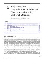
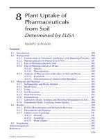
on land and construction costs. The results of calculations using Equation 9.4 are
plotted in Figure 9.1, which indicate the potential depth of sludge that could be
frozen at all locations in the United States. This figure or Equation 9.3 can be
TABLE 9.8
Maximum Depth of Frost Penetration and Potential Depth
of Frozen Sludge
Location
Maximum Frost
Penetration (cm)
Potential Depth of
Frozen Sludge (cm)
Bangor, Maine 183 221
Concord, New Hampshire 152 166
Hartford, Connecticut 124 117
Pittsburgh, Pennsylvania 97 70
Chicago, Illinois 122 113
Duluth, Minnesota 206 261
Minneapolis, Minnesota 190 233
Montreal, Quebec 203 256
FIGURE 9.1 Potential depth of sludge that could be frozen when applied in 8-cm layers.
DK804X_C009.fm Page 447 Thursday, July 21, 2005 8:10 AM
© 2006 by Taylor & Francis Group, LLC
448 Natural Wastewater Treatment Systems
used for preliminary estimates, but the final design should be based on actual
weather records for the site and the calculation procedure described earlier.
9.3.3.5 Thaw Period
The time required to thaw the frozen sludge can be calculated using Equation
9.2 and the appropriate thawing index. Frozen sludge will drain quite rapidly. In
field trials with wastewater sludges in New Hampshire, solids concentrations
approached 25% as soon as the material was completely thawed (Reed et al.,
1984). An additional 2 weeks of drying produced a solids concentration of 54%.
The sludge particles retain their transformed characteristics, and subsequent rain-
fall on the bed will drain immediately, as indicated by the fact that the solids
concentration was still about 40% 12 hours after an intense rainfall (4 cm) at the
New Hampshire field trial (Reed et al., 1984). The effects for a variety of different
sludge types are reported in Table 9.9.
9.3.4 SLUDGE FREEZING FACILITIES AND PROCEDURES
The same basic facility can be used for water treatment sludges and wastewater
sludges. The area can be designed as either a series of underdrained beds, similar
TABLE 9.9
Effects of Sludge Freezing
Percent Solids Content
Location and Sludge Type
Before
Freezing
After
Freezing
Cincinnati, Ohio
Wastewater sludge, with alum 0.7 18
Water treatment, with iron salts 7.6 36
Water treatment, with alum 3.3 27
Ontario, Canada
Waste-activated sludge 0.6 17
Anaerobically digested 5.1 26
Aerobically digested 2.2 21
Hanover, New Hampshire
Digested, wastewater sludge, with alum 2–7 25–35
Digested primary 3–8 30–35
Source: Data from Farrell(1970), Reed et al. (1984), Rush and Strickland
(1979), and Schleppenbach (1983).
DK804X_C009.fm Page 448 Thursday, July 21, 2005 8:10 AM
© 2006 by Taylor & Francis Group, LLC
Sludge Management and Treatment 449
in detail to conventional sand drying beds, or deep, lined, and underdrained
trenches. The Duluth, Minnesota, water treatment plant uses the trench concept
(Schleppenbach, 1983). The sludges are pumped to the trenches on a routine basis
throughout the year. Any supernatant is drawn off just prior to the onset of winter.
After an initial ice layer has formed, sludge is pumped up from beneath the ice,
spread in repeated layers on the ice surface, and allowed to freeze. The sand bed
approach requires sludge storage elsewhere and application to the bed after the
freezing season has begun.
9.3.4.1 Effect of Snow
Neither beds nor trenches require a roof or a cover. A light snowfall (less than 4
cm) will not interfere with the freezing, and the contribution of the meltwater to
the total mass will be negligible. What must be avoided is application of sludge
under a deep snow layer. The snow in this case will act as an insulator and retard
freezing of the sludge. Any deep snow layers should be removed prior to a new
sludge application.
9.3.4.2 Combined Systems
If freezing is the only method used to dewater wastewater sludges, then storage
is required during warm periods. A more cost-effective alternative is to combine
winter freezing with polymer-assisted summer dewatering on the same bed. In a
typical case, winter sludge application might start in November and continue in
layers until about 3 ft (1 m) of frozen material has accumulated. In most locations,
this will thaw and drain by early summer. Polymer-assisted dewatering can then
continue on the same beds during the summer and early fall. Sludge storage in
deep trenches during the warm months is better suited for water treatment oper-
ations where putrefaction and odors are not a problem.
9.3.4.3 Sludge Removal
It is recommended that the drained wastewater sludges be removed each year.
Inert chemical sludges from water treatment and industrial operations can remain
in place for several years. In these cases, a trench 7 to 10 ft (2 to 3 m) deep can
be constructed, so the dried solids residue remains on the bottom. In addition to
new construction, the sludge freezing concept can allow the use of existing
conventional sand beds, which are not now used in the winter months.
Example 9.2
A community near Pittsburgh, Pennsylvania, is considering freezing as the dew-
atering method for their estimated annual wastewater sludge production of 0.4
million gallons (1500 m
3
, 7% solids). Maximum frost penetration (from Table
9.8) is 38 in. (97 cm).
DK804X_C009.fm Page 449 Thursday, July 21, 2005 8:10 AM
© 2006 by Taylor & Francis Group, LLC
450 Natural Wastewater Treatment Systems
Solution
1. Use Equation 9.4 to determine potential design depth of frozen sludge:
ΣY = 1.76(F
p
) – 101 = 1.76(97) – 101 = 70 cm
2. Then, determine the bed area required for freezing:
This area could be provided by 16 freezing beds, each 7 m by 20 m.
Allow 30 cm for freeboard. Constructed depth = 0.70 + 0.30 = 1.0 m.
3. Determine the time required to thaw the 0.70-m sludge layer, if average
temperatures are 10°C in March, 17°C in April, and 21°C in May. Use
Equation 9.3 with a sludge depth of 70 cm:
(March) + (April) + (May 1–17)
∆T · t = (31)(10) + (30)(17) + (17)(21) = 1177°C·d
Therefore, the sludge layer should be completely thawed by May 18
under the assumed conditions.
9.3.4.4 Sludge Quality
Although the detention time for sludge on the freezing beds may be several
months, the low temperatures involved will preserve the pathogens rather than
destroy them. As a result, the process can be considered only as a conditioning
and dewatering operation, with little additional stabilization provided; however,
wastewater sludges treated in this way may be “cleaner” than sludges that are air
dried on typical sand beds. This is due to the rapid drainage of sludge liquid after
thawing, which carries away a significant portion of the dissolved contaminants.
In contrast, air-dried sludges will still contain most of the metal salts and other
evaporation residues.
9.4 REED BEDS
Reed bed systems are similar in some ways to the vertical flow constructed
wetlands described in Chapter 7. In this case, the bed is composed of selected
media supporting emergent vegetation, and the flow path for liquid is vertical
rather than horizontal. These systems have been used for wastewater treatment,
Area
1500 m
0.70 m
2143 m
3
2
==
∆Tt
Y
m
⋅=
=°⋅
2
1177 C d
DK804X_C009.fm Page 450 Thursday, July 21, 2005 8:10 AM
© 2006 by Taylor & Francis Group, LLC
Sludge Management and Treatment 451
landfill leachate treatment, and sludge dewatering. This section describes the
sludge dewatering use, where the bed is typically underdrained and the percolate
is returned to the basic process for further treatment. These beds are similar in
concept and function to conventional sand drying beds.
In conventional sand beds, each layer of sludge must be removed when it
reaches the desired moisture content, prior to application of the next sludge layer.
In the reed bed concept, the sludge layers remain on the bed and accumulate over
a period of many years before removal is necessary. The significant cost savings
from this infrequent cleaning are the major advantage of reed beds. Frequent
sludge removal is necessary on conventional sand beds, as the sludge layer
develops a crust and becomes relatively impermeable, with the result that subse-
quent layers do not drain properly and the new crust prevents complete evapora-
tion. When reeds are used on the bed, the penetration of the stems through the
previous layers of sludge maintains adequate drainage pathways and the plant
contributes directly to dewatering through evapotranspiration.
This sludge dewatering method is in use in Europe, and approximately 50
operational systems are located in the United States. All of the operational beds
have been planted with the common reed Phragmites. Experience has shown that
it is necessary to apply well-stabilized wastewater sludges to these beds. Aero-
bically or anaerobically digested sludges are acceptable, but untreated raw sludges
with a high organic content will overwhelm the oxygen-transfer capability of the
plants and may kill the vegetation. The concept will also work successfully with
inorganic water treatment plant sludges and high-pH lime sludges.
The structural facility for a reed bed is similar in construction to an open,
underdrained sand drying bed. Typically, either concrete or a heavy membrane
liner is used to prevent groundwater contamination. The bottom medium layer is
usually 10 in. (25 cm) of washed gravel (20 mm) and contains the underdrain
piping for percolate collection. An intermediate layer of pea gravel about 3 in.
(8 cm) thick prevents intrusion of sand into the lower gravel. The top layer is 4
in. (10 cm) of filter sand (0.3 to 0.6 mm). The Phragmites rhizomes are planted
at the interface between the sand and gravel layers. At least 3 ft (1 m) of freeboard
is provided for long-term sludge accumulation. The Phragmites are planted on
about 12-in. (30-cm) centers, and the vegetation is allowed to become well
established before the first sludge application (Banks and Davis, 1983b).
9.4.1 FUNCTION OF VEGETATION
The root system of the vegetation absorbs water from the sludge, which is then
lost to the atmosphere via evapotranspiration. It is estimated that during the warm
growing season this evapotranspiration pathway can account for up to 40% of
the liquid applied to the bed. As described in Chapter 7, these plants are capable
of transmitting oxygen from the leaf to the roots; thus, aerobic microsites (on the
root surfaces) exist in an otherwise anaerobic environment that can assist in sludge
stabilization and mineralization.
DK804X_C009.fm Page 451 Thursday, July 21, 2005 8:10 AM
© 2006 by Taylor & Francis Group, LLC
452 Natural Wastewater Treatment Systems
9.4.2 DESIGN REQUIREMENTS
Sludge application to these reed beds is similar to the freezing process previously
described, in that sequential layers of sludge are applied during the operational
season. The solids content of the sludge can range up to 4%, but 1.5 to 2% is
preferred (Banks and Davis, 1983a). Solids content greater than 4% will not allow
uniform distribution of the sludge on the densely vegetated bed. The annual
loading rate is a function of the solids content and whether the sludge has been
digested anaerobically or aerobically. Aerobically digested sludges impose less
stress on the plants and can be applied at slightly higher rates. At 2% solids,
anaerobically digested sludges can be applied at a hydraulic loading of about 25
gal/ft
2
·yr (1 m
3
/m
2
·yr) and aerobically digested sludges at 50 gal/ft
2
·yr (2
m
3
/m
2
·yr). The corresponding solids loadings would be 4.2 lb/ft
2
·yr (20 kg/m
2
·yr)
for anaerobic sludges and 8.3 lb/ft
2
·yr (40 kg/m
2
·yr) for aerobic sludges. For each
1% increase in solids content (up to 4%), the hydraulic loading should be reduced
by about 10% (for example, for aerobic sludge at 4% solids, the hydraulic loading
is 1.6 m
3
/m
2
·yr). For comparison, the recommended solids loading on conven-
tional sand beds would be about 16.4 lb/ft
2
·yr (80 kg/m
2
·yr) for typical activated
sludges. This suggests that the total surface area required for these reed beds will
be larger than for conventional sand beds.
The typical operational cycle allows a sludge application every 10 d during
the warm months and every 20 to 24 d during the winter. This schedule allows
28 sludge applications per year; for 2% solids aerobic sludges, each layer of
sludge would be about 4 in. (10.7 cm). It is recommended that during the first
year of operation the loadings be limited to one half the design values to limit
stress on the developing plants.
An annual harvest of the Phragmites plants is typically recommended. This
usually occurs during the winter months, after the top of the sludge has frozen.
Electrical or gasoline-powered hedge clippers can be used. The plant stems are
cut at a point that will still be above the top of the sludge layers expected during
the remainder of the winter. This allows the continued transfer of air to the roots
and rhizomes. In the spring, the new growth will push up through the accumulated
sludge layers without trouble. The harvest produces about 25 ton/ac, dry solids
2.5 ton/ac (56 mt, wet weight per hectare). The major purpose of the harvest is
to physically remove this annual plant production and thereby allow the maximum
sludge accumulation on the bed. The harvested material can be composted or
burned.
Sludge applications on a bed are stopped about 6 months before the time
selected for cleaning. This allows additional undisturbed residence time for the
pathogen content of the upper layer to be reduced. Typically, sludge application
is stopped in early spring, and the bed is cleaned out in late fall. The cleaning
operation removes all of the accumulated sludge in addition to the upper portion
of the sand layer. New sand is then placed to restore the original depth. New
plant growth occurs from the roots and rhizomes that are present in the gravel
layer.
DK804X_C009.fm Page 452 Thursday, July 21, 2005 8:10 AM
© 2006 by Taylor & Francis Group, LLC
Sludge Management and Treatment 453
The number of separate reed beds at a facility will depend on the frequency
of sludge wasting and the volume wasted during each event. Typically, the winter
period controls the design because of the less frequent sludge applications (21
to 24 d of resting) permitted. For example, assume that a facility wastes aerobi-
cally digested sludge on a daily basis at a rate of 10 m
3
/d (2% solids). The
minimum total bed area required is (10 m
3
/d)(365 d/yr)/(2 m
3
/m
2
·yr) = 1825 m
2
.
Try 12 beds, each 152 m
2
in area; assume that each is loaded for 2 d in sequence
to produce a 24-d resting cycle during the winter months. The unit loading is
then (10 m
3
/d)(2 d)/(152 m
2
) = 0.13 m = 13 cm. This is close to the recommended
10.7-cm layer depth for a single application; therefore, in this case, a minimum
of 12 cells would be acceptable.
9.4.3 PERFORMANCE
It is estimated that 75 to 80% of the volatile solids (VSS) in the sludge will be
reduced during the long detention time on the bed. As a result of this reduction
and the moisture loss, a 10-ft-deep (3-m) annual application will be reduced to
2.4 to 4 in. (6 to 10 cm) of residual sludge. The useful life of the bed is therefore
6 to 10 yr between cleaning cycles. With one exception, all the reed bed systems
in the United States are located where some freezing weather occurs each winter.
The exception is the reed bed system at Fort Campbell, Kentucky. Observations
at these systems indicate that the volume reduction experienced at Fort Campbell
is significantly less than that experienced at systems in colder climates. The reason
is believed to be the freezing and thawing of the sludge that occurs in the colder
climates, which results in much more effective drainage of water from the accu-
mulated sludge layers. This suggests that reed beds in cold climates should follow
the criteria described in a previous section for freezing rather than the arbitrary
21-d cycle for winter sludge applications. This should result in a more effective
process and, in colder climates, more frequent sludge application.
The loss of volatile solids during the long detention time on these reed beds
raises the concern that the metals concentration of the residual sludges could
increase to the point where beneficial uses of the material or normal disposal
options are limited. Table 9.10 summarizes data from the reed bed system serving
the community of Beverly, New Jersey. The reed bed system in Beverly has been
in operation for 7 yr; therefore, the average age of the accumulated sludge was
3.5 yr. The applied sludges sampled from 1990 to 1992 are believed to be
representative of the entire period. The tabulated data on accumulated sludge
represents a core sample of the entire 7-yr sludge accumulation on the bed. The
total volatile solids experienced a 71% reduction, and the total solids demonstrate
a 251% increase due to the effective dewatering. All of the metals concentrations
show an increase. If beneficial use of the removed sludge is a project goal, it is
suggested that the critical metals in the accumulated sludge be measured on an
annual basis. These data will provide the basis for following the trend of increas-
ing concentration and can be used to decide when to remove the sludge from the
bed prior to developing unacceptable metal concentrations.
DK804X_C009.fm Page 453 Thursday, July 21, 2005 8:10 AM
© 2006 by Taylor & Francis Group, LLC
454 Natural Wastewater Treatment Systems
Another issue of concern in some states is the use of Phragmites on these
systems. The Phragmites plant has little habitat value and has been known to
crowd out more beneficial vegetation species in marshes. The risk of seeds or
other plant material escaping from the operational reed bed and infesting a natural
marsh is negligible; however, when the sludge is cleaned out of the bed, some
root and rhizome material may also be removed with the sludge. The final sludge
disposal site may have to be considered if regrowth of the Phragmites at that site
would pose a problem. Disposal in landfills or utilization in normal agricultural
applications should not create problems. If it is absolutely necessary, the removed
sludges can be screened and the root and rhizome stock separated. It also should
be possible to stockpile the removed sludge and cover it with dark plastic for
several additional months to kill the rhizome material.
9.4.4 BENEFITS
The major advantage of the reed bed concept is the ease of operation and main-
tenance and the very high final solids content (suitable for landfill disposal). This
significantly reduces the cost for sludge removal and transport. A 6- to 7-yr
cleaning cycle for the beds seems to be a reasonable assumption. One disadvantage
TABLE 9.10
Comparison of Applied vs. Accumulated Sludge
Parameter
Applied
Sludges
a
Accumulated
Sludge
b
Total solids (%) 7.1 17.8
Volatile solids (%) 81.14 56
pH 5.3 6
Arsenic (mg/kg) 0.64 1
Cadmium (mg/kg) 6 8.3
Chromium (mg/kg) 16.3 62.3
Copper (mg/kg) 996.5 2120
Lead (mg/kg) 510 1130
Mercury (mg/kg) 10.2 28.3
Nickel (mg/kg) 29.8 45.7
Zinc (mg/kg) 4150 6400
a
Digested primary sludges applied to the bed from 1990 to 1992.
b
Accumulated dewatered sludge on the bed March 12, 1992.
Source: Costic & Associates, Engineers Report: Washington Town-
ship Utilities Authority Sludge Treatment Facility, Costic & Asso-
ciates, Long Valley, NJ, 1983. With permission.
DK804X_C009.fm Page 454 Thursday, July 21, 2005 8:10 AM
© 2006 by Taylor & Francis Group, LLC
Sludge Management and Treatment 455
is the requirement for an annual harvest of the vegetation and disposal of that
material; however, over a 7-yr cycle, the total mass of sludge residue and vegetation
requiring disposal will be less than the sludge requiring disposal from sand drying
beds or other forms of mechanical dewatering.
Example 9.3
A community near Pittsburgh, Pennsylvania (see Example 9.2), produces 3000
m
3
of sludge (at 3.5% solids) per year. Compare reed beds for dewatering with
a combination reed–freezing bed system.
Solution
Assume a 4-month freezing season, a design loading for reeds of 2.0 m
3
/m
2
, and
a design depth for freezing of 70 cm (satisfactory value; Example 9.2 indicates
a maximum potential depth of 70 cm as feasible). Use 12 beds:
1. Calculate bed area if reed dewatering is used alone:
The schedule allows 28 sludge applications per year to the reed beds.
Then, 3000 m
3
/12 beds/28 applications/125 m
2
/bed = 0.07 m/applica-
tion = 7 cm.
2. 21 warm-weather applications = 21 × 7 cm = 147 cm.
7 winter applications using reed bed criteria = 7 × 7 = 49 cm.
3. Freeze–thaw criteria allow a total winter application of 70 cm; there-
fore, an additional 21 cm or three additional applications are allowed,
for a total of 10, and an annual total of 31. At 31 annual applications,
the allowable loading is 2.17 m
3
/m
2
·yr, and the required bed area is
3000 m
3
/2.17 m
3
/m
2
·yr = 1382 m
2
, so each of the individual beds can
be reduced in area to 115 m
2
. This savings in area might be very
significant in climates colder than in New Jersey.
9.4.5 SLUDGE QUALITY
The dewatered material removed from the reed beds will be similar in character
to composted sludge with respect to pathogen content and stabilization of organ-
ics. The long detention times combined with the final 6-month rest period prior
to sludge removal ensure a stable final product for reuse or disposal. If metals
are a concern, then a routine monitoring program can track the metals content of
the accumulating sludge. In some cases, the metal content may be the basis for
sludge removal rather than the volumetric capacity of the bed.
Total area
3000 m
2m /m yr
1500 m
Individual bed
1500 m
12
125 m
3
32
2
2
2
=
−
=
==
DK804X_C009.fm Page 455 Thursday, July 21, 2005 8:10 AM
© 2006 by Taylor & Francis Group, LLC
456 Natural Wastewater Treatment Systems
9.5 VERMISTABILIZATION
Vermistabilization (i.e., sludge stabilization and dewatering using earthworms)
has been investigated in numerous locations and has been successfully tested full
scale on a pilot basis (Donovan, 1981; Eastman et al., 2001). A potential cost
advantage for the concept in wastewater treatment systems is the capability for
stabilization and dewatering in one step as compared to thickening, digestion,
conditioning, and dewatering in a conventional process. Vermistabilization has
also been used successfully with dewatered sludges and solid wastes. The concept
is feasible only for sludges that contain sufficient organic matter and nutrients to
support the worm population.
9.5.1 WORM SPECIES
In most locations, the facilities required for the vermistabilization procedure will
be similar to an underdrained sand drying bed enclosed in a heated shelter. Studies
at Cornell University evaluated four earthworm species: Eisenia foetida, Eudrilus
eugeniae, Pheretima hawayana, and Perionyx excavatus. E. foetida showed the
best growth and reproductive responses, with temperatures in the range of 68 to
77°F (20 to 25°C). Temperatures near the upper end of the range are necessary
for optimum growth of the other species. Worms are placed on the bed in a single
initial application of about 0.4 lb/ft
2
(2 kg/m
2
) (live weight). Sludge loading rates
of about 0.2 lb/ft
3
/wk (1000 g of sludge volatile solids per m
2
per wk) were
recommended for liquid primary and liquid waste-activated sludge (Loehr et al.,
1984). Liquid sludges used in the Cornell University tests ranged from 0.6 to
1.3% solids, and the final stabilized solids ranged from 14 to 24% total solids
(Loehr et al., 1984). The final stabilized sludge had about the same characteristics
regardless of the type of liquid sludge initially applied. Typical values were as
follows:
•Total solids (TS) = 14–24%
•Volatile solids = 460–550 g per kg TS
• Chemical oxygen demand = 606–730 g per kg TS
•Organic nitrogen = 27–35 g per kg TS
• pH = 6.6–7.1
Thickened and dewatered sludges have also been used in operations in Texas with
essentially the same results (Donovan, 1981). Application of very liquid sludges
(<1%) is feasible as long as the liquid drains rapidly so aerobic conditions can
be maintained in the unit. Final sludge removal from the unit is required only at
long intervals, about 12 months.
9.5.2 LOADING CRITERIA
The recommended loading of 0.2 lb/ft
2
·wk (1000 g/m
2
·wk) is equivalent, for
typical sludges, to a design area requirement of 4.5 ft
2
/capita (0.417 m
2
/capita).
DK804X_C009.fm Page 456 Thursday, July 21, 2005 8:10 AM
© 2006 by Taylor & Francis Group, LLC
Sludge Management and Treatment 457
This is about 2.5 times larger than a conventional sand drying bed. The construc-
tion cost difference will be even greater, as the vermistabilization bed must be
covered and possibly heated; however, major cost savings are possible for the
overall system, because thickening, digestion, and dewatering units may not be
required if vermistabilization is used with liquid sludges.
9.5.3 PROCEDURES AND PERFORMANCE
At an operation in Lufkin, Texas, thickened (3.5 to 4% solids) primary and waste-
activated sludge are sprayed at a rate of 0.05 lb/ft
2
·d (0.24 kg/m
2
·d) dry solids
over beds containing worms and sawdust. The latter acts as a bulking agent and
absorbs some of the liquid, assisting in maintaining aerobic conditions. An addi-
tional layer of sawdust, 1 to 2 in. (2.5 to 5 cm) thick, is added to the bed after
about 2 months. The original sawdust depth was about 8 in. (20 cm) when the
beds were placed in operation. The mixture of earthworms, castings, and sawdust
is removed every 6 to 12 months. A small front-end loader is driven into the bed
to move the material into windrows. A food source is spread adjacent to the
windrows, and within 2 days essentially all the worms have migrated to the new
material. The concentrated worms are collected and used to inoculate a new bed.
The castings and sawdust residue are removed, and the bed is prepared for the
next cycles.
Human pathogen reduction in a field experiment with vermiculture (vermi-
composting) was found to reduce fecal coliforms, Salmonella spp., enteric
viruses, and helminth ova more effectively than composting (Eastman et al.,
2001). The ratio of earthworms (Eisenia foetida) to biosolids was 1:1.5 wet
weight. After 144 hr, fecal coliforms showed a 6.4-log reduction, while a control
experiment showed only a 1.6-log reduction. Salmonella spp. reduction was 8.6
log, and the control reduction was 4.9 log. Enteric viruses were reduced by 4.6
log as compared to 1.8 log reduction in the control. Helminth ova reduction was
1.9 log vs. 0.6 log in the control.
Example 9.4
Determine the bed area required to utilize vermistabilization for a municipal
wastewater treatment facility serving 10,000 to 15,000 people. Compare the
advantages of liquid vs. thickened sludge.
Solution:
1. Assuming an activated sludge system or the equivalent, the daily sludge
production will be about 1 mt dry solids per day. If the sludge contains
about 65% volatile solids (see Table 9.2), the Cornell loading rate of
1 kg /m
2
·wk is equal to 1.54 kg/m
2
·wk of total solids. Assume downtime
of 2 wk per year for bed cleaning and general maintenance. The Lufkin,
Texas, loading rate for thickened sludge is equal to 1.78 kg/m
2
·wk of
total solids.
2. Calculate the bed area for liquid (1% solids or less) and for thickened
(3 to 4% solids) sludges.
DK804X_C009.fm Page 457 Thursday, July 21, 2005 8:10 AM
© 2006 by Taylor & Francis Group, LLC
458 Natural Wastewater Treatment Systems
For liquid sludge:
Bed area = (1000 kg/d)(365 d/yr)/(1.54 kg/m
2
·wk)(50 wk) = 4740 m
2
For thickened sludge:
Bed area = (1000 kg/d)(365 d/yr)/(1.78 kg(m
2
·wk)(50 wk) = 4101 m
2
3. A cost analysis is required to identify the most cost-effective alterna-
tive. The smaller bed area for the second case is offset by the added
costs required to build and operate a sludge thickener.
9.5.4 SLUDGE QUALITY
The sludge organics pass through the gut of the worm and emerge as dry, virtually
odorless castings. These are suitable for use as a soil amendment or low-order
fertilizer if metal and organic chemical content are within acceptable limits (see
Table 9.16 for metals criteria). Only limited quantitative data are available with
regard to removal of pathogens with this process. The Texas Department of Health
found no Salmonella in either the castings or the earthworms at a vermistabili-
zation operation in Shelbyville, Texas, that received raw sludge (Donovan, 1981).
A market may exist for the excess earthworms harvested from the system. The
major prospect is as bait for freshwater sport fishing. Use as animal or fish food
in commercial operations has also been suggested, but numerous studies have
shown that earthworms accumulate very significant quantities of cadmium, cop-
per, and zinc from wastewater sludges and sludge-amended soils; therefore,
worms from a sludge operation should not be the major food source for animals
or fish in the commercial production of food for human consumption.
9.6 COMPARISON OF BED-TYPE OPERATIONS
The physical plants for freezing systems, reed systems, and vermistabilization
systems are similar in appearance and function. In all cases, a bed is required to
contain the sand or other support medium, the bed must be underdrained, and a
method for uniform distribution of sludge is essential. Vermistabilization beds
must be covered and probably heated during the winter months in most of the
United States. The other two concepts require neither heat nor covers. Table 9.11
summarizes the criteria and the performance expectations for these three concepts.
The annual loading rate for the vermistabilization process is much less than for
the other concepts discussed in this section; however, vermistabilization may still
be cost effective in small to moderate-sized operations, as thickening, digestion,
conditioning, and dewatering can all be eliminated from the basic process design.
Freezing sludge does not provide any further stabilization. Digestion or other
stabilization of wastewater sludges is strongly recommended prior to application
on freezing or reed beds to avoid odor problems.
DK804X_C009.fm Page 458 Thursday, July 21, 2005 8:10 AM
© 2006 by Taylor & Francis Group, LLC
Sludge Management and Treatment 459
9.7 COMPOSTING
Composting is a biological process for the concurrent stabilization and dewatering
of sludges. If temperature and reaction time satisfy the required criteria, the final
product should meet the class A pathogen and vector attraction reduction require-
ments (see Chapter 3). The three basic types of compost systems are (USEPA,
1981a):
• Windrow — The material to be composted is placed in long rows,
which are periodically turned and mixed to expose new surfaces to the
air.
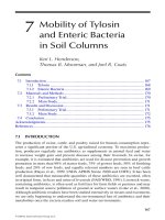
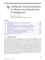
• Static pile — The material to be composted is placed in a pile, and air
is either blown or drawn through the pile by mechanical means. Figure
9.2 illustrates the various configurations of static pile systems.
• Enclosed reactors — These can range from complete, self-contained
reactor units to structures that partially or completely enclose static
pile or windrow-type operations. The enclosure in these latter cases is
usually for odor and climate control.
TABLE 9.11
Comparison of Bed-Type Operations
Factor
Sludge Types Freezing (All)
Reeds
(Nontoxic)
a
Freezing
and Reeds
(Nontoxic)
Worms
(Organic
Nontoxic)
Bed enclosure None None None Yes
Heat required No No No Yes
Initial solids (%) 1–8 3–4 3–8 1–4
Typical loading rate
(kg/m
2
/yr)
b
40
c
60 50 <20
Final solids (%) 20–50
d
50–90
d
20–90
d
15–25
Further stabilization
provided
No Some Some Yes
Sludge removal
frequency (yr)
110
e
10
e
1
a
Assumes year-round operation in a warm climate.
b
Annual loading in terms of dry solids.
c
Includes use of bed for conventional drying in summer.
d
Final solids amount depends on length of final drying period.
e
The vegetation is typically harvested annually.
DK804X_C009.fm Page 459 Thursday, July 21, 2005 8:10 AM
© 2006 by Taylor & Francis Group, LLC
460 Natural Wastewater Treatment Systems
The process does not require digestion or stabilization of sludge prior to
composting, although there may be increased odor production issues to deal with
when composting raw sludges. Composting projects are frequently designed
based on 20% solids, but many operating projects are starting with 12 to 18%
solids and as a result end up using more bulking agent to absorb moisture to get
to approximately 40% solids in the mix of sludge and bulking agent. The end
product is useful as a soil conditioner (and is sold for that purpose in many
locations) and has good storage characteristics.
The major process requirements include: oxygen at 10 to 15%, a carbon-to-
nitrogen ratio of 26:1 to 30:1, volatile solids over 30%, water content 50 to 60%,
and pH 6 to 11. High concentrations of metals, salts, or toxic substances may
affect the process as well as the end use of the final product. Ambient site
temperatures and precipitation can have a direct influence on the operation. Most
municipal sludges are too wet and too dense to be effectively composted alone,
so the use of a bulking agent is necessary. Bulking agents that have been used
successfully include wood chips, bark, leaves, corncobs, paper, straw, peanut and
FIGURE 9.2
Static pile composting systems: (a) single static pile; (b) extended aerated pile.
Screened
compost
Screened
compost
Wood chips
and sludge
Wood chips
and sludge
Porous base:
Wood chips
or compost
Porous base:
Wood chips
or compost
Nonperforated pipe
except for water
condensate drain
holes
Nonperforated pipe
except for water
condensate drain holes
Perforated pipe
Perforated pipe
Exhaust fan
Exhaust fan
Filter pile
screened
compost
Filter pile
screened
compost
(a)
(b)
DK804X_C009.fm Page 460 Thursday, July 21, 2005 8:10 AM
© 2006 by Taylor & Francis Group, LLC
Sludge Management and Treatment 461
rice hulls, shredded tires, sawdust, dried sludge, and finished compost. Wood
chips have been the most common agent and are often separated from the finished
compost mixture and used again. The amount of bulking agent required is a
function of sludge moisture content. The mixture of sludge and bulking agent
should have a moisture content between 50 and 60% for effective composting.
Sludges with 15 to 25% solids might require a ratio of between 2:1 and a 3:1 of
wood chips to sludge to attain the desired moisture content in the mixture
(USDA/USEPA, 1980).
Mixing of the sludge and the bulking agent can be accomplished with a front-
end loader for small operations. Pugmill mixers, rototillers, and special compost-
ing machines are more effective and better suited for larger operations (USEPA,
1984). Similar equipment is also used to build, turn, and tear down the piles or
windrows. Vibratory-deck, rotary, and trommel screens have all been used when
separation and recovery of the bulking agent are process requirements. The pad
area for either windrow or aerated pile composting should be paved. Concrete
has been the most successful paving material. Asphalt may be suitable, but it may
soften at higher composting temperatures and may itself be susceptible to com-
posting reactions.
Outdoor composting operations have been somewhat successful in Maine and
in other locations with severe winter conditions. The labor and other operational
requirements are more costly for such conditions. Covering the composting pads
with a simple shed roof will provide greater control and flexibility and is recom-
mended for sites that will be exposed to subfreezing temperatures and significant
precipitation. If odor control is a concern, it may be necessary to add walls to
the structure and include odor control devices in the ventilation system.
For static pile systems, the aeration piping shown in Figure 9.2 is typically
surrounded by a base of wood chips or unscreened compost about 12 to 18 in.
(30 to 45 cm) deep. This base ensures uniform air distribution and also absorbs
excess moisture. In some cases, permanent air ducts are cast into the concrete
base pad. The mixture of sludge and bulking agent is then placed on the porous
base material. Experience has shown that the total pile height should not exceed
13 ft (4 m) to avoid aeration problems. Typically, the height is limited by the
capabilities of most front-end loaders. A blanket of screened or unscreened
compost is used to cover the pile for thermal insulation and to adsorb odors.
About 18 in. (45 cm) of unscreened or about 10 in. (25 cm) of screened compost
is used. Where the extended pile configuration is used, an insulating layer only
3 in. (8 cm) thick is applied to the side that will support the next composting
addition. Wood chips or other coarse material are not recommended, as the loose
structure will promote heat loss and odors.
The configuration shown in Figure 9.2 draws air into the pile and exhausts
it through a filter pile of screened compost. This pile should contain about 35 ft
3
(1 m
3
) of screened compost for every 3.3 ton (3 mt) of sludge dry solids in the
compost pile. To be effective, this filter pile must remain dry; when the moisture
content reaches 70%, the pile should be replaced.
DK804X_C009.fm Page 461 Thursday, July 21, 2005 8:10 AM
© 2006 by Taylor & Francis Group, LLC