Tribology Handbook 2 2010 Part 8 pot
Bạn đang xem bản rút gọn của tài liệu. Xem và tải ngay bản đầy đủ của tài liệu tại đây (1.37 MB, 40 trang )
625
Packed
glands
The main applications of packed glands are for sealing the stems of valves, the shafts
of
rotary pumps and the plungers
of
reciprocating pumps. With a correct choice ofgland design and packing material they can operate for extended periods with
the minimum need for adjustment.
VALVE STEMS
Valve stem packings use up
to
5 rings of packing material
as in Figure 25.1. For high temperature/high pressure
steam, moulded rings of expanded graphite foil material
are
commonly used. This gives low valve stem friction.
To reduce the risk of extrusion of the lamellar graphite
during frequent valve operation, the end rings of the
packing can be made from graphite/yarn filament.
Materials of this type only compress in service by a
small amount and can provide a virtually maintenance
free valve packing if used with live loading as shown in
Figure 25.2.
ROTARY
PUMPS
Rotary pump glands commonly use up to 5 rings of
packing material. For most applications up to
a
PV
of
150 bar m/sec (sealed pressure
X
shaft surface speed) a
simple design
as
in Figure
25.3
is adequate.
In
most
pumps the pressure at the gland will be 5 bar
or
less and
those with pressures over
10
bar will be exceptional.
At
PV
values over 150 bar m/sec direct water cooling
or
jacket cooling are usually necessary and typical arrange-
ments are shown in Figure 25.4 and 25.5.
When pumping abrasive or toxic fluids there may be a
need to provide a flushing fluid entry
at
the fluid end
of
the
glands, as in Figure 25.6,
or
a
high pressure barrier fluid
which is usually injected near the centre of the gland as in
Figure 25.7.
Figure 25.1
A
typical valve stem packing
DISC
SPRING
STACK
STUD
SPACER
SLEEVE
BRAIDED
GRAPHITE
EXPANDED
GRAPHITE
BRAIDED
GRAPH
IT€
Figure 25.2
A
valve stem packing using spring
loading to maintain compression
of
the valve
packing and avoid leakage
LIQUID
GLAND
FOLLOWER
Figure 25.3
A
general duty rotary pump gland
625.1
Packed
glands
B25
LANTERN
RING
COOLING
WATER
IN
LET
Figure 25.4
,A
gland packing with direct cooling via
a lantern ring
FLUSHING
FLUID
Figure 25.6
A
packing gland with a flushing fluid
system
RECIPROCATING
PUMPS
Reciprocating pumps
also
use typically
5
packing rings.
However due
to
the increased risk
of
extrusion
of
the
packing due
ito
the combination
of
high pressure and
reciprocating movement, an1 i extrusion elements are
usually incorporated in the gland.
Self adjusting glands can be used on reciprocating
pumps but the spring loading
for
compression take up
must act in the same direction as the fluid pressure
loading, as shown
in
Figure
25.10.
JACKET
COOLING
JACKET
COOLING
PTF
E
ANTI-EXTRUSION
RING
uI
f
u
Figure
25.5
A
gland packing with a cooling jacket
for high temperature applications
BARRIER
FLUID
I
Figure
25.7
A
packed gland with a barrier fluid
system
Figure
25.8
A
reciprocating pump gland with
PTFE
anti-extrusion washers between the packing rings
Figure 25.10
A
reciprocating pump gland with
internal spring loading to maintain compression
of
the packing
Figure
25.9
A
reciprocating pump gland with an
anti-extrusion moulded hard fabric lip seal
B25.2
B25
Packed glands
PACKING MATERIALS
Table
25.1
Materials for
use
in packed glands
Material
Maximum operating
temperature
“C
Special properties Typical application5
Expanded graphite foil 550°C Low friction, self lubrication, Valve stems
2500°C in non-oxidising low compression set and
constituents. Available as
rings
environments contains no volatile
Graphite/yarn filament 550°C Available as cross plaited
square section lengths.
Resistant to extrusion
Valve stems
Aramid (Kevlar) fibre 250°C Tough and abrasion resistant Valve stems and pumps
PTFE filament 250°C
Low friction and good
chemical resistance
Valve stems
Pumps at surface speeds below
10
m/s
Hybrid graphite/PTFE yarn 250°C Particularly suitable for high
speed rotary shafts.
Close bush clearances needed
to reduce risk of extrusion.
Good resistance to abrasives.
Pump shafts for speeds of the
order
of
25 m/s
Ramie
120°C Good water resistance
~~~ ~
__
Rotary and reciprocating
water pumps
Note:
Many
of
these packings can be provided with a central rubber core which can increase their elasticity and thus assist in
maintaining the gland compression. Their application depends on the temperature and chemical resistance of the type of rubber used.
PACKING DIMENSIONS AND
FITTING
Typical gland dimensions are shown
in
Figure
25.1
1
and packing sizes in Table
25.2.
Table
25.2
Typical radial housing widths in relation to shaft diameters. All dimensions in mm
All packings except expanded graphite Exponded graphite
Shajl
diameter Housing radial width Shaft diameter Housing radial width
up to 12
above 12
to
18
18
to
25
25
to
50
50
to
90
90
to
150
150
3
5
6.5
8
10
12.5
15
up to
18
3
above 18 to 75 5
150 and above
10
75 to 150 7.5
825.3
Packed glands
B25
A=7W
r
FIRST OBSTRUCTION
/
P-
ROTATING SHAFT
(DEPTH
7W
APPLIES WHEN LANTERN GLAND
IS
USED)
RECIPROCATING SHAFT
Figure
25.11
Typical gland dimensions for rotating and reciprocating shafts
Pump
shafts, valve stems and reciprocating rams should have a surface finish of better than
0.4
pm
Ra.
Their hardness
should not be less than
250
Brinell.
Rings should be cut with square butt joins and each fitted individually with joins staggered at a minimum of
90".
After
applying a small degree
of
compression to the complete set, gland nuts must be slackened
off
to finger tight prior
to
start up.
Once running, any excessive leakage can then be gradually reduced by repeated small degrees of adjustment. The major
cause of packing failure
is
excessive compression, particularly at the initial fitting stage.
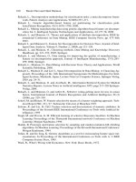
Further advice may be obtained from packing manufacturers.
B25.4
_______~
B26
Mechanical
piston
rod
packinqs
The figure shows a typical general arrangement of a
FLANGE STUD
mechanical rod packing assembly. The packing (sealing)
rings are free to move radially in the cups and are given an
axial clearance appropriate to the materials used (see
Table
26.2).
The back clearance is in the range of
1
to
5
mm.
(&
to in). The diametral clearance of the cups is
chosen to prevent contact with the rod; it lies typically in
the range
1
to
5
mm
(A
to
6
in). The sealing faces on the
rings and cups are accurately ground
or
lapped.
The case material can be cast iron, carbon steel, stain-
less steel or bronze to suit the chemical conditions. It may
be drilled to provide lubricant feed to the packing, to vent
leakage gas
or
to provide water cooling.
The rings are held in contact with the rod by spring
pressure; sealing action however, depends
on
gas forces
which hold the rings radially in contact with the rod and
axially against the next cup.
PRESS
END
CONNECTION
GASKE
Figure
26.1
General arrangement
of
a typical
mechanical piston rod packing assembly
SELECTION
OF
TYPE
OF
PACKING
1
Pressure breaker
Description
Three-piece ring with bore matching rod. Total circumfe-
rential clearance
0.25
mm. Garter spring to ensure contact
with rod.
Applications
Used in first one
or
two compartments next to high
pressure, when sealing pressure above
35
bar
(500
psi)
to reduce pressure and pressure fluctuations on sealing
rings.
2
Radial cut/Tangential cut pair
Description
The radial cut ring
is
mounted on the high pressure side.
(Two tangential cut rings can be used when there
is
a
reversing pressure drop.) The rings are pegged
to
prevent
the radial slots from lining up. Garter springs are fitted
to
ensure rod contact. Ring bores match the rod.
Applications
The standard design of segmental packing. Used for both
metallic and filled
PTFE
packings.
_~._______.
.
TANGENT
'IAL
OR
RADIAL CUT RING
B26.1
Mechanical
piston
rod
packings
B26
3
Unequal segment ring
Description
The rings are pegged to prevent the gaps lining
up.
Garter
springs are fitted
to
ensure rod contact. The bore of the
larger segment matches the rod.
Applications
Rather more robust than tangentially cut rings
(2)
and
hence more suitable for carbon-graphite packings.
4
Contracting rod packing
Description
Cast iron L-ring with bronze
or
white metal inner ring or
three piece packing with filled PTFE and metallic back-up
ring. Contact with rod maintained by ring tension. Rings
pegged to prevent the gaps from lining
up.
Note:
this style
of packing has to be assembled over the end of the rod.
Applications
Used for both metallic and filled PTFE packings.
5
Cone ring
Description
Three ring seal-each ring in three segments with bore,
matching rod. Cone angle ranging from
75"
at pressure
end to
45"
at atmosphere end.
Applications
Used
for
both metallic and filled
PTFE
packings.
B26.2
B26
Mechanical piston
rod
packings
DESIGN
OF
PACKING ARRANGEMENT
Number
of
sealing rings
There
is
no
theoretical basis
for
determining the number of
sealing
rings. Table
26.1
gives values that are typical of
good
practice:
Table 26.1 The number of sealing rings for
various pressures
Pressure
No.
of
sets
of
sealing rings
up to 10 bar (150 p.s.i.) 3
10-20 bar (150-250 p.s.i.) 4
20-35 bar (250-500 psi.) 5
35-70
bar (500-1000 p.s.i.)
6
70-1
50 bar (1OOC-2000 p.s.i.)
8
above 150 bar (2000 p.s.i.)
9-12
Piston rods
Rod
material
is
chosen
for
strength
or
chemical resistance.
Carbon,
low
alloy and
high
chromium
steels are suitable.
For
the harder
packings
(lead
bronze
and
cast iron)
hardened rods should
be
used;
treatment can be flame
or
induction hardening,
or
nitriding. Chrome plating
or
high
chromium steel
is
used
for
chemical resistance.
Surface finish
Metal and filled
PTFE
packing
0.2-0.4
pm
R,
(8-16
pin
cla)
.
Carbodgraphite and metal/graphite sinters 0.1-0.2 pm
R,
(4-8
pin cla)
Dimensional tolerances
Diameter
Taper over stroked length
*
0.01
mm
(0.0005
in)’
Out-of-roundness
0.025
mm
(0.001
in)
f0.05
mm
(+0.002
in)
-0.05
mm
(-0.002
in)
Notes:
1 With Type 4 packings increase number of sealing rings
by
50-100%.
be adequate.
breakers (Type
1)
in addition, on the pressure side.
‘2
With Type 5 packings
four
sets
of
sealing rings should
3
Above 35 bar (500 psi) use one
or
two pressure
Packing materials
Table
26.2
The types of packing material and their applications
Material
Rod
hardness
Axial
clearance
Applications
(1)
Lead-bronze 250 BHN min 0.08-0.12
mm
Optimum material with high thermal conductivity and good
(0.003-0.005 in)
lubricated bearing properties. Used where chemical
conditions allow. Suitable for pressures up to
3000
bar
(50
000
psi.)
(2)
Flake graphite
400
BHN min 0.08-0.12 mm
(0.003-0.005 in)
Cheaper alternative to
(1);
bore may be tin coated to assist
grey cast
iron
running in. Suitable
up
to
70
bar (1000 p.s.i.)
for
lubricated
operation
(3)
White metal not critical 0.08-0.12 mm
(0.003-0.005 in)
Used where (1) and
(2)
not suitable because
of
chemical
(Babbitt)
conditions. Preferred material for high chromium steel and
chrome-plated rods. Max. pressure
350
bar (5000 psi).
Max. temperature 120°C
(4) Filled
PTFE
400
BHN
min 0.4-0.5 mm Suitable
for
unlubricated and marginally lubricated operation
(0.015-0.020 in)
as well as fully lubricated. Very good chemical resistance.
Above
25
bar
(400
psi.)
a
lead bronze backing
ring
(0.1/0.2 mm) clear of rod should be used to give support
and improved heat removal
(5) Reinforced p.f. not critical
0.25-0.4 mm
Used with
sour
hydrocarbon gases and where lubricant may
resin (0.010-0.015 in) be thinned by solvents in gas stream
(6)
Carbon-graphite
400
BHN min
0.03-0.06
mm
(0.0014.002 in)
Used with carbon-graphite piston rings. Must be kept
oil
free.
Suitable up to 350°C
(7)
Graphite/metal 250 BHN min
0.08-0.
12
mm Alternative to (4) and
(6)
sinter (0.003-0.005 in)
B26.3
Mechanical piston
rod
packings
B26
FllTilNG AND RUNNING
IN
1.
Cleanliness
is
essential
so
that cups bear squarely
together
and to prevent scuffing or damage at start
up.
2.
Handle segments carefully to avoid damage during
assembly.
3.
Check packings float freely in cups.
4.
With lubricated packings, check that plenty
of
oil is
present before starting
to
run-in. Oil line must have a
check valve between the lubricator and the packing.
Manually fill the oil lines before starting.
Use
maxi-
mum lubrication feed rate during run-in.
5.
If the temperature of the rod rises excessively (say
above
100°C)
during run-in,
stop
and allow
to
cool and
then re-start run-in.
6.
Run
in with
short
no-load period.
B26.4
B27
Soft
piston
seals
SELECTION AND DESIGN
Table
27.1
Guidance on the selection
of
basic types
l&e
name
Distributor
‘u’
CUP
‘0’
rinz
External-fitted to piston, sealing in bore
COMPRESSION
Internal-fitted in housing, sealing on piston
or
rod
Simple housing design Good
Good
Poor
Very good
Low
wear rate
Very good Good Good
Poor
High stability (resistance to roll) Good Fair Very good
Po01
Low
friction
Fair Fair Fair
Good
Resistance to extrusion Good Good Good Fair
Availability in small sizes
Fair Good
Poor
Very good
Availability in large sizes
Good Fair Good Good
Bidirectional sealing Single-acting only. Use in pairs back-to-back for
double-acting. ‘Non-return’ valve action can
be useful pairs
Effective but
usually used in
Remarks
Do
not
allow heel to touch mating surface
Use correct fits and guided piston, etc.
Avoid parting
line flash on
the sealing
except under high pressure.
If seal
too
soft for
pressure,
lip may curl away
Unsuitable for
from surface rotational
movement
Application
notes
acetal resin, nylon, PTFE, glass fibre/PTFE
or
metal
bearings.
To
prevent mixing of unlike fluids, e.g. aeration
of
oil,
use
two
seals and vent the space in between to atmosphere.
Long lips take up wear better and improve stability but
increase friction. Use plastic back-up rings to reduce
extrusion at high pressures. The use
of
a thin oil will
reduce wear but may increase friction.
For
pneumatic
assemblies use light grease which may contain colloidal
graphite
or
MoS2.
Choose light hydraulic oil
for
mist
lubrication.
Avoid metal-to-metal contact due to side loading
or
piston weight.
If
seals will not maintain concentricity use
B27.1
VENT
TO
ATMOSPHERE
Soft
piston
seals
B27
Table
27.2
Seals derived from basic
types
Table
27.3
Special
seals
~~
Double-acting, one-piece, narrow width,
but preswre can be trapped between
lips and seal may jam. Needs
composire piston
Similar, but no pressure trap and can be
fitted to one-piece piston
Derived from
‘0’
ring. Less tendency to
roll.
Improved and multiple sealing
surfaces. Sealing forces reduced and
parting line flash removed from
working surface
Multiple sealing lips to obviate leakage
due
to
curl
_.
.
~
e~
‘W’
section. Good
for
hydraulic
applications and high pressures. Can
be used internally
or
externally
Material
Rubber
Dynamic seal
on
piston
‘\“‘
Register between body Polyethylene
sections
Static seal
in
body
sections
Dynamic seal
on
piston
Piston head seal Polyethylene
SPRING
Fits
‘0’
ring groove. Usually
Use internally
or
F’TFE
externally. Suitable for
rotational movement.
Table
27.4
Mating surface materials
Materials
ryPe
Finish
Remarks
0.6
pm max.
0.2
to
0.4
pm
(8
to
16
pin) preferred
0.2
pm rnax.
0.05
to
0.1
prn
(2
to
4
,pin)
preferred
Best untreated materials. Improve
High cost.
J
with use.
Brass
As
drawn
Copper As drawn
J
Liable to
SCUE
and corrode.
J
Low cost
Aluminium
As
drawn
alloy
Polished
J
Anodised
/
/
J
Low
cost.
Short life
Abrasive, therefore polish
Hard
anodised
Corrodes.
Mild steel
As
drawn
Corrodes readily
Very abrasive, polish before and
Honed
Hard chrome
J
after plating. High cost.
plated
Used mostly for piston
rods
Ground
d
J
~~
Stainless steel
Ground
Notes:
Anodising
and plating can be
porous
to
air
causing apparent seal leakage. The
finish
on the seal housing can
be
0.8
pm.
Use
rust
prevention treatment for
mild
steel in storage.
B27.2
B27
Soft
piston
seals
INSTALLAT1BN
Table
27.5
Assembly hazards
Problem
Suggested
solution
Multiple seal grooves
External grooves
Internal grooves
Crossing
ports
Crossing threads
Crossing
edges and circlip grooves
Fitting piston assemblies to bores
M
plastic
blade
-use
light
greasc
Tilt
Deburr, chamfer, use assembly sleeve
or
temporary plug in port
Use
thin
wall sleeve
Deburr
or
chamfer
B
B27.3
Soft
piston
seals
627
Table
27.6
‘0‘
ring
fits
Hydraulic
Pneumatic
INTERFERENCE
LARGE
CLEARANCE
SMALL
SMALL
INTERFERENCE
LARGE
CLEARANCE
Dimensions
tQ
BS
1806
High friction Low friction
No
standard available
Rapid wear Slow wear
Extrudes
into
ports
Will pass small ports
Small radial clearance
Seal supports piston Piston unsupported
Large clearance possible
Moderate bore and housing tolerances
Close tolerances
on
‘0’
ring
dimensions,
bore
and groove width
-~
Tolerant to material swell and shrinkage
Seals at zero pressure drop
Sensitive to swell and shrinkage
Seals gas
at
low pressure-under 1 p.s.i. with
0.003
in
Unsuitable for liquids at any pressure
clearance
on
width
FAILURE
Table
27.7
Types and
causes
of
failure
TVpe
Usual
symptom
Cause
~
~~~
Channelling (fluid cutting)
Small, straight grooves across the sealing Fluid leaking across seal at high velocity
surface
Abrasive wear
~ ~~
Flat on
‘0’
ring
Circumferential groove
on
lip seal
Sharp sealing edge on lip
seal
Pressure too
high
or
abrasive mating surface
~-
Extrusion
Surface broken
Slivers
of
rubber
Pressure
too
high
or
too
much clearance
-~
Chemical
attack
Softening
or
hardening-may break up Incompatible fluid
Temperature effects
Hardening and breaking up
Breaking
up
Too
coId
Too
hot
and/or excess friction
~~~
~___
Notes:
Symptoms ofcontamination by solid particles are similar
to
channelling but the grooves are less regular.
Uneven
distribution of wear
suggests eccentricity or side loading.
‘0’
ring rolling produces variation in shape and size
of
section.
B27.4
Selection
of
lubricant
twe
c1
Table
1.
P
importance
of
lubricant properties in relation to bearing type
?jpe
of
component
Plain journal
Open
gears,
Clock
and
Hinges,
slides,
Lubricant
propeirty
\
bearing
bearing
closed
gear'
ropes,
chainr,
etc.
inrtrument
piuots
latches,
etc.
~~ ~ ~~
1.
Boundary lubricating
properties
2.
Cooling
3.
Friction
or
torque
4.
Ability to
remain
in
bearing
5.
Ability to
seal
out contaminants,
6.
Temperature range
7.
Protection
against
corrosion
8.
Voiatility
+
++
+
+
-
+
+
+
++
++
++
++
++
++
++
+
+++
++
+++
++
-
-
+
+
++
+
-
-
++
++
-
-
~
++
-
++
+++
-
++
+
+
+
+
+
Note:
The relative importance
of
each lubricant property in
a
particular class
of
component
is
indicated on a scale
from
+
+
+
=
highly important
to
-
=
quite unimportant.
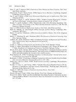
2
10
Speed,
ft/min
-
100
1000
10000
100
000
7
00
(330
10000
E
.
5
1000
100
Speed
at
bearing
contact,
mm/s
-t
Figure
1.1
SpeedAoad limitations
for
different types
of
lubricant
c1.1
c1
Selection
of
lubricant
type
0
LIFE,
h
Figure
1.2
Temperature limits for mineral oils
.LPOUR
POINT'
LIMIT
'FOR
SILICONES
AND
ESTERS
I
I
-1
00
1
2
345
10
20
30
40
50
100
200
300
400
500
1000
2000
3000
4000
5000
10 000
LIFE,
h
Figure
7.3
Temperature limits for some synthetic oils
c1.2
Selection
of
lubricant twe
CI
3
2
345
10
20
30
40
50
100
200
300
400500
1000
2000
300040005000
10000
LIFE,
h
Figure
1.4
liemperature limits for
greases.
In
many
cases the grease life will be controlled by volatility
or
migration. This cannot be depicted simply, as it varies
with pressure and the degree
of
ventilation,
but
in
general the
hnits
may
be
slightly
below
the oxidation
limits
30
20
10
0
10
2030405060708090100 120
Temperature,
'C
Figure
1.5
Viscosit y/temperature characteristics
of
various
oils
The effective viscosity
of
a lubricant in a bearing may be
different from the quoted viscosity measured
by
a standard
test method, and the difference depends
on
the shear rate
in the bearing.
bearings
may
-
2
-
Shear
rate
in
Shear rate
in
-5
200
-
standard test
._
methods
is
low
I
be
high
al
W
c
W
I
i
r
r
!
I
I
1
1
Typical
SA€
20/50
mineral oil at
10OoC
.Typical
SA€
30
mineral
oil at
100°C
1-
I
I
\I
100
1000
10000
100000
lO0OC
Shear rate
(s-'
)
0
Hgure
1.6
Variation
of
ViSMIsity
with
shear rate
C1.3
CI
Selection
of
lubricant type
Table
7.2
Examples of specific mechanisms and possible lubricants and systems
Lubricating
Lubricant
system
Journal bearings
Oil By hand
Circulating
system
Ring
lubrication
Porous
bearings
~ ~
Maintenance Inuestment Rate
of
heat
cost cost removal
ty
lubricant
Remarks
High
Low
Small Only for light duty
Low
High High Necessary oil
flow
must be ensured
Low
Low
Moderate Only for moderate circumferential speeds
Low Low
Small
Only for moderate circumferential speeds and
low
specific pressures
Grease By hand High
Low
Nil
Centralised
Low
High Nil
system
Only for light duty
Good pumpahility of grease required if long
lines to bearings
Rolling hearings
Oil Oil mist
Low
High Small If compressed air in necessary quantity and
cleanliness available, investment costs are
moderate
Circulating Low High High
system
Bath
Low Low
Small
Oil feed jets must
be
properly designed and
positioned to ensure optimum lubrication
and heat removal
Careful design and filling required to avoid
excessive churning
Splash
Low Low
Moderate Careful design of housing and other
components (e.g. gears) necessary
to
ensure
adequate
oil
supply
Greas Packed
Low Low
Nil Overfilling must be avoided. Maintenance
costs are only low if re-lubrication period
not
too
short
Centralised
Low
High Nil Possibility for used grease
to
escape must be
system
provided. Shield delivery lines from heat
Gears
Oil Bath
Low Low
Moderate Careful design of housing required to ensure
adequate oil supply to all gears and to avoid
excessive churning
Circulating
Low
High High Jets have to be properly designed and placed
to ensure even oil distribution and heat
removal
system
Grease
By
hand High
Low
Nil Only for light duty
Housing
Low Low
Nil Principally for small, low-speed gears,
filled otherwise,
use
stiffer greases to avoid
slumping and overheating
C1.4
Mineral
oils
c2
CLASS1
FI
CAT10
N
Mineral oils are basically hydrocarbons, but
all
contain
thousands of different types of varying structure, molecular
weight and volatility, as well as minor but important
amounts
of
hydrocarbon derivatives containing one or
more of the elements nitrogen, oxygen and sulphur. They
are classified
in
various ways as follows.
'Types
of
crude petroleum
Parafinic
Naphthenic
Mixed base
Contains significant amounts of waxy hydro-
carbons and has 'wax'
pour
point (see below)
but little
or
no asphaltic matter. Their naph-
thenes have long side-chains.
Contains asphaltic matter in least volatile
fractions, but little
or
no wax. Their naph-
thenes have short side-chains. Has 'viscosity'
pour point.
Clontains both waxy and asphaltic materials.
Their naphthenes have moderate to long side-
chains.
Has
'wax'
pour
point.
Viscosity
index
Lubricating oils are also commonly classified by their
change in kinematic viscosity with temperature, i.e. by
their kinematic viscosity index
or
KVI. Formerly,
KVIs
ranged between
0
and
100
only, the higher figures repre-
senting lower degrees
of
viscosity change with temperature,
but nowadays oils may be obtained with
KVIs
outside
these limits. They are generally grouped into high, medium
and low,
as
in
Table 2.1.
Table
2,9
Classification by viscosity index
Group
Kinematic uiscosity
index
Low
viscosity index
(LVI)
Below
35
Medium
viscosity
index
(MVI)
35-80
High
viscosity
index
(HVI)
80-1
10
~
Very high viscosity
index
(VHVI)
Over
110
Traditional
use
Dating from before viscosity could be measured accur-
ately, mineral oils were roughly classified into viscosity
grades by their typical uses
as
follows:
Spindle oils
Low viscosity
oils
(e.g. below about 0.01
Ns/m2
at
60DC,) suitable for thelubrica-
tion of high-speed bearings such as
textile spindles.
Medium viscosity oils (e.g. 0.01-0.02
Ns/mZ) at 60°C, suitable for machinery
running at moderate speeds.
Heavy rnachine
oils
Higher viscosity
oils
(e.g.
0.02-0.10
Ns/mZ) at 60DC, suitable
for slow-moving
machinery.
Suitable for the lubrication
of
steam
engine cylinder; viscosities from 0.12 to
0.3
Ns/m2 at
60°C
Light machine
oils
Cylinder
oils
Hydrocarbon types
The various hydrocarbon types are classified as follows:
(a)
Chemically saturated (i.e.
no
doubie valence
bonds) straight and branched chain. (Paraffins
or alkanes.)
(b)
Saturated
5-
and 6-membered rings with attached
side-chains
of
various lengths
up
to
20
carbon
atoms long. (Naphthenes.)
(E)
As
(b)
but also containing
1,2
or more 6-membered
unsaturated ring groups, i.e. containing double
valence bonds, e.g. mono-aromatics, di-aromatics,
polynuclear aromatics, respectively.
A
typical paraffinic lubricating oil may have these
hydrocarbon
types
in
the
proportions
given
in
Table
2.2.
Table
2.1
Hydrocarbon types in Venezuelan
95
VI
solvent extracted and dewaxed distillate
yo
Volume
Hydrocarbon
types
Paraffins
15
Naphthenes
60
Saturates
(KVI
=
105)
It
should be noted, however, that in Table 2.5 viscosity
index has been determined from dynamic viscosities by
the method
of
Roelands,
Blok
and Vlugter,' since this
is
a more fundamental system and allows truer comparison
between mineral
oils.
Except for
low
viscosity oils, when
DVIs are higher than KVIs, there is little difference
between KVI and DVI for mineral oils.
Mono-aromatics
18
Di-aromatics
6
Poly-aromatics
1
Aromatics
The VI
of
the saturates has a predominant influence
on the
VI
of
the oil. In paraffinic oils the
VI
of
the saturates
may be 105-120 and 60-80 in naphthenic
oils.
c2.1
c2
Mineral
oils
Structural group analyses
This is a useful way of accurately characterising mineral
oils and of obtaining
a
general picture of their structure
which is particularly relevant to physical properties, e.g.
increase of viscosity with pressure. From certain other
physical properties the statistical distribution of carbon
atoms in aromatic groups
(%eA),
in naphthenic groups
(%
CN),
in paraffinic groups
(%
Cp),
and the total number
(RT)
of naphthenic and aromatic rings
(RN
and
RA)
joined together. Table
2.3
presents examples on
a
number
of typical oils.
Table
2.3
Typical structural group analyses
(courtesy: Institution
of
Mechanical Engineers)
Spec@
grauip
at
15~6°C
%%%
cA
cN
cP
RA
RN
RT
Viscosip
Mean
Ns/m2 molecular
at
100°C
weighf
Oil
pppc
LVI spindle oil 0.926 0.0027 280
22
32
46
0.8 1.4 2.2
~~~~ ~ ~~
LVI heavy machine oil
0.943
0.0074 370
23 26 51 1.1 1.6 2.7
MVI light machine oil 0.882
0.0039 385
4 37 59 0.2
2.1
2.3
MVI heavy machine oil 0.910
0.0075
440
8 37
54
0.4
2.7
3.1
HVI light machine
oil
0.871
0.0043
405 6
26
68 0.3 1.4 1.7
HVI heavy machine oil 0.883
0.0091 520
7
23
70 0.4 1.8 2.2
~~
HVI cylinder
oil
0.899 0.0268 685
Medicinal white oil
0.890
0.0065 445
0
42 58
0
2.8 2.8
R
EFl
Nl
NG
Distillation
Lubricants
are
produced from crude petroleum by dis-
tillation according to the outline scheme given in Figure
2.1.
DISTILLATE
{GASOLINE]
-(KEROSINE
I
I
OR
LONG
RESIDUE
BASE
OILS)
Figure
2.1
(courtesy:
Institution
of
Mechanical
Engineers)
The
second distillation is carried out under vacuum
to
avoid subjecting the oil to temperatures over about
370°C,
which would rapidly crack the oil.
The vacuum residues
of
naphthenic crudes are bitu-
mens. These are not usually classified
as
lubricants but
are used
as
such
on
some plain bearings subject to
high
temperatures
and
as
blending components in oils and
greases to form very viscous lubricants for open gears,
etc.
Refining processes
Table
2.4
Refining processes
(courtesy:
Institution
of
Mechanical Engineers)
Proccss
Purpose
De-waxing Removes waxy materials from paraf-
finic and mixed-base oils
to
prevent
early solidification when the oil is
cooled to low temperatures, i.e.
to
reduce
pour
point
De-asphal ting Removes asphaltic matter, particu-
lady from mixed-base short residues,
which would separate
out
at
hig5
and low temperatures and block
oil-ways
Solvent extraction
Removes more highly aromatic mat-
erials, chiefly the polyaromatics,
in order
to
improve oxidation
stability
Hydrotreating
Reduces sulphur content, and accord-
ing
to
severity, reduces aromatic
content
by
conversion
to
naphthenes
Acid treatment Now mainly used
as
additional
to
other treatments
to
produce special
qualities such
as
transformer oils,
white
oils
and medicinal oils
Earth treatment
Mainly
to
obtain rapid separation
of
oil from water, i.e.
good
demulsi-
bility
c2.2
Mineral
oils
c2
The distillates and residues are used to a minor extent
as such, but generally they are treated or refined both
before and after vacuum distillation to fit them for the
more stringent requirement!;. The principal processes
listed in Table
2.4
are selected
to
suit the type
of
crude oil
and the properties required.
Elimination of aromatics increases the VI of an oil. A
lightly refined naphthenic oil may be LVI but MVI if
highly refined. Similarly
a
lightly refined mixed-base
oil
may be
MVI
but HVI if highly refined. Elimination of
aromatics also reduces nitrogen, oxygen and sulphur
contents.
The distillates and residues may be used alone
or
blended
together. Additionally, minor amounts of fatty oils or
of
special oil-soluble chemicals (additives) are blended in
to
form additive engine
oils,
cutting oils, gear oils, hydraulic
oils, turbine oils, and
so
on, with superior properties to
plain oils, as discussed below.
The tolerance in blend
viscosity for commercial branded oils is typically
*4y0
but official standards usually have wider limits, e.g.
&
10%
for
IS0
3448.
PHYSICAL
PROPERTIES
Viscosity Temperature
Figure
2.4
illustrates the variation
of
viscosity with
temperature for a series of
oils
with kinematic viscosity
index of
95
(dynamic viscosity index
93).
Figure
2.2
shows
the difference between
150
Grade
IS0
3448
oils with
KVIs
of
0
and
95.
Vi
scosity P ressu re
The viscosity of oils increases significantly under pres-
sure. Naphthtenic oils are more affected than paraffinic
but, very roughly, both double their viscosity for every
35
MN/m2
increase
of
pressure. Figure
2.3
gives an
impression
of
the variation
in
viscosity
of
an
SAE
20LY
IS0
3448
or medium machine oil,
HVI
type, with both
temperature and pressure.
In elastohydrodynamic (e hl) formulae it is usually
assumed that the viscosity increases exponentially with
pressure. Though in fact considerable deviations from an
exponential increase may occur at high pressures, the
assumption is valid up to pressures which control ehl
behaviour, i.e. about
35
MN/m2.
Typical pressure viscosity
coefficients are given in Table
2.5,
together with other
physical properties~
Pour
point
De-waxed paraffinic oils still contain
1%
or
so
of waxy
hydrocarbons, whereas naphthenic oils only have traces
of them. At about
O"C,
according to the degree
of
de-
waxing, the waxes in paraffinic oils crystallise out of
solution and at about
-IOo@
the crystals grow to the
extent that
the
remaining
oil
can no longer
flow.
This
temperature, or close
to
it, when determined under
specified conditions
is
known as the pour point. Naph-
thenic
oils,
in
contrast, simply become
so
viscous with
decreasing temperature that they
fail
to flow, although no
wax crystal structure develops. Paraffinic oils are therefore
said to have 'wax' pour points while naphthenic oils are
said
to
have 'viscosity' pour points.
50
000
20
000
10
000
2000
1000
500
10.0
8.0'
6.0
5.0
4.0
3.0
-20
-
Temperature,
"C
Figure
2.2
150
grade
IS0
3448
oils
of
0
and
95
KW
Figure
2.3
Variation
of
viscosity with temperature
and pressure
of
an
SAE
2OW
(HVI) oil
(courtesy.
Institution
of
Mechanical Engineers)
C2.3
3Q
3L
39
41
01
9
0
9-
0
L-
Mineral
oils
62
Thermal
properties
Table
25
Typical physical properties
of
highly refined mineral oils
(courtesy:
institution
of
Mechanical Engineers)
Naphthenic oils Parajinic
oils
Light Heavy Light Heauy
machine machine machine machine
cy1inde'
Density (kg/m3) at 25°C 862 880 897 862 875 89
1
Viscositv (rnNs/mZ) at 30°C 18.6 45.0
171
42.0 153 810
60°C 6.3 12.0
31
13.5 34 135
100°C 2.4 3.9 7.5 4.3 9.1
27
Dynamic viscosity index 92 68 38 109
96
96
Kinematic viscositv index 45 45 43
98
95 95
Pour point,
"G
-
43
-40
-
29 -9 -9 -9
Pressure-viscosity coefficient (,mZ/N
x
lo8) at 30°C 2.1 2.6
2.8
2.2
2.4 3.4
Isentropic secant bulk modulus at 35
MN/mz
and 30°C
- -
-
198 206
-
60°C
1.6 2.0 2.3
I
.9
2.1
2.8
100°C
1.3 1.6
1
.a
1.4 1.6
2.2
60°C
-
-
-
172
177
-
100°C
-
-
-
141
149
-
Thermal capacity
(J/kg
"C)
at 30°C 1880 1860 1850 I960 1910 1880
60°C 1990 1960 1910 2020 2010 1990
100°C 2120 2100 2080 2170 2150 2120
Thermal conductivity (Wm/m2 "C) at 30°C 0.132 0.130 0.128 0.133 0.131 0.128
60°C 0.131 0.128 0.126 0.131 0.129 0.126
100°C 0.127 0.125 0.123 0.127 0.126 0.123
Temperature
("C)
for vapour pressure
of
0.001 mmHg 35
60
95
95
110 125
Flash point, open, "C 163 175 210
227
257 300
D
ETE
R
IO
RATIO
N
Factors influencing oxidation
Lubricating
oils
can become unfit for further service by:
Temperature
Oxygen access
Rate doubles for every
8-10°C
temperature
rise.
Degree of agitation
of
the
oil
with air.
oxidation, thermal decomposition, and contamination.
Oxidation
Cutalysb
Particularly iron and copper in finely
divided or soluble form.
Mineral
oils
are
very stable relative to fatty oils and pure
hydrocarbons. This stability is ascribed to the combination
TOP-@
rate
Replenishment
of
inhibition (natural or
of saturated
and
unsaturated hydrocarbons and to certain
added).
of
the hydrocarbon derivatives, Le. compounds containing
Oil
ope
Proportions and type of aromatics and
oxygen, nitrogen and sulphur atoms-the so-called 'natural
especially on the compounds containing
inhibitors'. nitrogen, oxygen, sulphur.
Table
2.6
Effects of oxidation and methods of test
Type5
of
product produced oxidation Factors involved Methods
gtest
Organic acids,which are liable to corrode
Total acid number or neutralisation value,
cadmium, lead and zinc and thereby
to
types
of products depend
on
the condi- which assesses the Concentration
of
uromoee the formation of emulsions organic acids, and is therefore an in-
The relative proportions of the various
tions
of
oxidation and the type
of
oil
-
dication
of
the concentration
of
the
usually materials, more
is
the
deleterious
convenient
polymerised
and
precise test
to
carry out. Limits vary
between
0.2
mg
KOH/g
and
4.0
or
Lightly polymerised materials which in-
crease the viscosity
of
the
oil
Moderately polymerised materials which
become insoluble in the oil, especially
The degree of oxidation which can be
tolerated depends on the lubrication
System: more can
be
tolerated in simple
easily cleaned bath systems without
when cold. When dispersed these also
sensitive metals, less in complex circu-
mnre
__ _
-
promote emulsification and increase
of
viscosity. When settled out they clog
filter
screens and block oil-ways
formed
locally
on very hot surfaces
where they may remain
lation systems
With many additive
oils
proof
of
the
con-
tinued effective presence
of
the neces-
Highly polymerised coke-like materials sary additives, e.g. anti-oxidant,
is
more important
C2.5
c2
Mineral
oils
Thermal decomposition
Mineral oils are also relatively stable to thermal decom-
position in the absence of oxygen, but at temperatures
over about 330°C, dependent on time, mineral oils will
decompose into fragments, some of which polymerise to
form
hard
insoluble products.
Table
2.7
Thermal decomposition products
Product
Effect
Light hydrocarbons
Flash point is reduced; viscosity
is
reduced
Carbonaceous residues
Hard deposits on heater surfaces
reduce flow rates and accentu-
ate overheating
Some additives are more liable to thermal decom-
position than the base oils, e.g. extreme pressure additives;
and surface temperature may have to be limited to tem-
peratures
as
low as 130°C.
Con$amination
Contamination is probably the most common reason for
changing
an
oil. Contaminants may be classified as shown
in Table
2.8.
Table
2.8
Contaminants
7ype Example
Gaseous
Air,
ammonia
Liquid
Water, oil of another type
or
viscosity grade
or
both
Solid
Fuel soot, road dust,
fly
ash, wear products
Where appropriate, oils are formulated to cope with
likely contaminants, for example turbine oils are designed
to separate water and air rapidly, diesel engine oils are
designed to suspend fuel soot in harmless finely divided
form and to neutralise acids formed from combustion of
the fuel.
Solid contaminants may be coptrolled by appropriate
filtering
or
centrifuging
or
both. Limits depend on the
abrasiveness of the contaminant and the sensitivity
of
the
system.
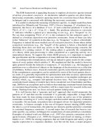
Oil
life
Summarising the data given under the headings Oxida-
tion
and
Thermal decomposition, above, Figure
2.5
gives an
indication
of
the time/temperature limits imposed by
thermal and oxidation stability on the life of
a
well-refined
HVI
paraffinic oil.
ADDITIVE
OILS
Plain mineral oils are used in many units and systems
for the lubrication of bearings, gears and other mechan-
isms where their oxidation stability, operating temperature
range, ability to prevent wear, etc., are adequate. Now-
adays, however, the requirements are often greater than
plain oils are able to provide, and special chemicals
or
additives are ‘added’
to
many oils to improve their
pro-
perties. The functions required of these ‘additives’ gives
them their common names listed in Table
2.9.
Table
2.9
Types
of
additives
Main
tvpc
Function
and
sub-lypes
Acid Neutralise contaminating strong acids
formed, for example, by combustion
of high sulphur fuels
or,
less often, by
decomposition
of
active EP additives
neutralisers
Anti-foam Reduces surface foam
Anti-oxidants Reduce oxidation. Various types are:
oxidation inhibitors, retarders; anti-
catalyst metal deactivators, metal pass-
ivators
Anti-rust
Reduces rusting of ferrous surfaces swept
by oil
Anti-wear
agents
Reduce wear and prevent scuffing of
rubbing surfaces under steady load
operating conditions; the nature of the
film is uncertain
Corrosion
Type
(a)
reduces corrosion
of
lead; type
(b)
reduces corrosion of cuprous metals inhibitors
Detergents Reduce or prevent deposits formed
at
high temperatures, e.g.
in
ic
engines
Dispersants
Prevent deposition
of
sludge
by
dispersing
a
finely divided suspension
of
the in-
soluble material formed
at
low
tem-
perature
Emulsifier Forms emulsions; either water-in-oil
or
oil-in-water according to type
Extreme Prevents scuffing of rubbing surfaces
under severe operating conditions, e.g.
heavy
shock
load, by formation of a
mainly inorganic surface film
pressure
Oiliness Reduces friction under boundary lubrica-
tion conditions
;
increases load-carrying
capacity
where
limited
by
temperature
rise by formation of mainly organic
surface
films
Pour point Reduces
pour
point of paraffinic oils
depressant
Tackiness
Reduces
loss
of oil by gravity,
e.g.
from
vertical sliding surfaces,
or
by centri-
fugal force
Viscosity index
Reduce the decrease in viscosity due
tc
improvers increase of temperature
C2.6
Mineral
oils
c2
Table
2.10
Types
of
additive oil required for various types of machinery
~~
Type
cf
machinery
Usual
base
oil
tyfe
Usual additives
Special
requirements
Food processing
Medicinal white
None Safety in case of ingestion
oil
Oil hydraulic Paraffinic down Anti-oxidant Minimum viscosity change with temperature;
to about Anti-rust minimum wear ofsteel/steel
-
20"C, Anti-wear
naphthenic Pour point
below depressant
VI improver
Anti-foam
Steam and gas turbines Paraffinic
or
Anti-oxidant Ready separation from water, good oxidation
naphthenic Anti-rust stability
distillates
Steam engine cylinders Unrefined
or
re-
fined residual
or
high-viscosity
distillates
None or fatty oil Maintenance of oil film on hot surfaces; re-
sistance to washing away by wet steam
Air
compressor cylinders Paraffinic
or
Anti-oxidant Low deposit formation tendency
naphthenic Anti-rust
distillates
Gears (steel/steel)
Paraffinic
or
Anti-wear, EP Protections against abrasion and scuffikg
naphthenic Anti-oxidant
Anti-foam
Pour point
depressant
Gears (steel
/
bronze)
Paraffinic Oiliness Reduce friction, temperature rise, wear and
Anti-oxidant oxidation
Machine tool slideways Paraffinic or Oiliness
;
Maintains smooth sliding at very low speeds.
naphthenic tackiness Keeps film on vertical surfaces
Hermetically sealed refrigerators Naphthenic None Good thermal stability, miscibility with re-
frigerant, low flow point
Diesel engines
Paraffinic
or
Detergent
Vary with type of engine thus affecting additive
naphthenic Dispersant combination
An ti-oxidan
t
Acid neutraliser
An ti-foam
Anti-wear
Corrosion
inhibitor
400
350
U
330
LIFE
IN
THIS
'REGION
DEPE~DS
UPON
2
250
OXYGEN ACCESS CATALYSIS, AND TOP-UP
z
w
;
200
+
150
100
50
OXYGEN STABILITY LIMIT
(UNLIMITED OXYGEN ACCESS
1 2
345
10
100
1000
10
000
LIFE,
h
Select
ion
of
add
it
ive
combinations
Additives and oils are combined
in
various ways to
provide the performance required.
It
must
be
emphasised,
however, that indiscriminate mixing
can
produce unde-
sired interactions, e.g. neutralisation
of
the effect
of
other
additives, corrosivity
and
the formation of insoluble
materials.
Indeed,
some additives may
be
included
In
a
blend
simply
to
overcome problems caused
by
other
additives.
The more properties
that
are
required
of
a
lubricant, and
the
more
additives
that
have
to
be
used
to
achieve the
result, the
greater
the
amount
of
testing
that
has
to
be
carried
out
to
ensure
satisfactory performance.
Figure
2.5
Approximate life of well-refined mineral
oils
(courtesy:
Institution
of
Mechanical Engineers)
C2.7
c3
Synthetic
oils
Application data
for
a variety
of
synthetic
oils
are given in
the
table below. The list is not complete, but most readily
available synthetic oils are included.
Table
3.1
Typical Chlorinated
Phenyl Phenyl
Methyl
Mcfhyl (inhibifcd)
Pohethm
Siliconc
Siliconc
Polyglycol Pe$uorinated
Qpical
Typical
Di-ester Phosphate Methyl
Proper@
Esk?
Silicone
Inhibited
~
Maximum temperature
250 300
I
IO
220 320 305 260
370
in absence ofoxygen ("C)
Maximum temperature
210 240
I10
180
250 230 200
310
in presence ofoxygen ("C)
Maximum temperature due I50 180
100
200 250 280
to decrease in viscosity
("C)
__
Minimum temperature due
-35 -65
-
55
-
50
-
30
-
65
-
20
-
60
to increase in viscosity ("C)
Density (g/ml)
0.91
1.01
1.12 0.97
1.06
I
.04 1.02
1.88
Viscosity index
145
140
0
200
175 195
160 100-300
Flash point ("C)
230
255 200 310 290 270
180
Spontaneous ignition Low Medium Very high High High Very high Medium
Very
&$
temperature
Thermal conductivity
0.15
0.14
0.13
0.16
0.15 0.15 0.15
WtM
"C)
Thermal capacity fJ/kg"C)
2000 1700
1600
1550 1550 1550
ZOO0
Bulk modulus Medium Medium Medium Very low
LOW
Low Medium
Low
Boundary lubrication Good Good Very good Fair but
poor
Fair but
poor
Good
for
steel on
steel steel
for
steel on
Verygood
Poor
Toxicity Slight Slight Some Non-toxic Non-toxic Non-toxic Believed to
Low
toxicity be
low
Suitable rubbers Nitrile, Silicone Butyl, Neoprene, Neoprene, Viton,
fluoro-
Nitrile
>[an\
silicone EPR viton viton silicone
Effect on plastics
May act
as
plasticisen Powerful Slight, but may Slight, but may Slight, but may Generally hiild
solvent leach out leach out leach out mild
plasticisers plasticisen plasticisers
~ ~~
Resistance to attack Good Good Fair Very good Very good Good Good
Very
good
by water
Resistance
to
chemicals Attacked by Attacked by Attacked by Attacked by Attacked by Attacked by Attacked by
Very
good
alkali alkali many strong alkali strong alkali alkali oxidants
chemicals
Effect on metals
~~
Slightly Corrosive to Enhance Non-corrosive Non-corrosive Corrosive in
Non-
Removes
oxic
corrosive
some
non- corrosion presence
of
corrosive films
at
to
non- ferrous in presence water to elevated
ferrous metals
of
water ferrous metals temperatur
metals when hot
Cost (relative to
4
6
6
15
25
40
4
500
mineral oil)
C3.1