Theory and Design of CNC Systems Part 1 pps
Bạn đang xem bản rút gọn của tài liệu. Xem và tải ngay bản đầy đủ của tài liệu tại đây (1.77 MB, 35 trang )
Springer Series in Advanced Manufacturing
Series Editor
Professor D.T. Pham
Manufacturing Engineering Centre
Cardiff University
Queen’s Building
Newport Road
Cardiff CF24 3AA
UK
Other titles in this series
Assembly Line Design
B. Rekiek and A. Delchambre
Advances in Design
H.A. ElMaraghy and W.H. ElMaraghy (Eds.)
Effective Resource Management in Manufacturing Systems:
Optimization Algorithms in Production Planning
M. Caramia and P. Dell’Olmo
Condition Monitoring and Control for Intelligent Manufacturing
L. Wang and R.X. Gao (Eds.)
Optimal Production Planning for PCB Assembly
W. Ho and P. Ji
Trends in Supply Chain Design and Management: Technologies and Methodologies
H. Jung, F.F. Chen and B. Jeong (Eds.)
Process Planning and Scheduling for Distributed Manufacturing
L. Wang and W. Shen (Eds.)
Collaborative Product Design and Manufacturing Methodologies and Applications
W.D. Li, S.K. Ong, A.Y.C. Nee and C. McMahon (Eds.)
Decision Making in the Manufacturing Environment
R. Venkata Rao
Frontiers in Computing Technologies for Manufacturing Applications
Y. Shimizu, Z. Zhang and R. Batres
Reverse Engineering: An Industrial Perspective
V. Raja and K.J. Fernandes (Eds.)
Automated Nanohandling by Microrobots
S. Fatikow
A Distributed Coordination Approach to Reconfigurable Process Control
N.N. Chokshi and D.C. McFarlane
ERP Systems and Organisational Change
B. Grabot, A. Mayère and I. Bazet (Eds.)
Machining Dynamics
K. Cheng (Ed.)
ANEMONA
V. Botti and A. Giret
Suk-Hwan Suh • Seong-Kyoon Kang
Dae-Hyuk Chung • Ian Stroud
Theory and Design
of CNC Systems
123
Suk-Hwan Suh, PhD
School of Mechanical & Industrial
Engineering
POSTECH, San 31, Pohang, 790-784
Republic of Korea
Seong-Kyoon Kang, PhD
K&S International Patent and Law Firm
3F, Hanjin Bldg., 607-12 Yeoksam-dong,
Kangnam-gu, Seoul, 135-907
Republic of Korea
Dae-Hyuk Chung, PhD
Doosan Infracore Co., Ltd.
601-3, Namsan-dong, Changwon-Si,
Gyeongnam-Do
Republic of Korea
Ian Stroud, PhD
École Polytechnique Fédérale
de Lausanne (EPFL)
STI-IGM-LICP, Station 9,
1015 Lausanne
Switzerland
ISBN 978-1-84800-335-4 e-ISBN 978-1-84800-336-1
DOI 10.1007/978-1-84800-336-1
Springer Series in Advanced Manufacturing ISSN 1860-5168
British Library Cataloguing in Publication Data
Theory and design of CNC systems. - (Springer series in
advanced manufacturing)
1. Machine-tools - Numerical control 2. Machine-tools -
Numerical control - Programming
I. Suh, Suk-Hwan
621.9'023'0285
ISBN-13: 9781848003354
Library of Congress Control Number: 2008928587
© 2008 Springer-Verlag London Limited
Apart from any fair dealing for the purposes of research or private study, or criticism or review, as permitte
d
under the Copyright, Designs and Patents Act 1988, this publication may only be reproduced, stored o
r
transmitted, in any form or by any means, with the prior permission in writing of the publishers, or in the cas
e
of reprographic reproduction in accordance with the terms of licences issued by the Copyright Licensing
Agency. Enquiries concerning reproduction outside those terms should be sent to the publishers.
The use of registered names, trademarks, etc. in this publication does not imply, even in the absence of
a
specific statement, that such names are exempt from the relevant laws and regulations and therefore free fo
r
general use.
The publisher makes no representation, express or implied, with regard to the accuracy of the informatio
n
contained in this book and cannot accept
any legal responsibility or liability for any errors or omissions tha
t
may be made.
Cover design: eStudio Calamar S.L., Girona, Spain
Printed on acid-free paper
9 8 7 6 5 4 3 2 1
springer.com
This book is dedicated to:
Eun-Sook Choi,
Hyeon-Jeong Lee,
Hye-Jung Kim,
and Hildegarde Nagy-Stroud
and to the rest of our families
for their endurance of this headlong task.
Preface
CNC controllers, working as a brain for manufacturing automation, are high value-
added products accounting for over 30% of the price of machine tools. CNC technol-
ogy is generally considered as a measure of the level of manufacturing technology of
a nation, and is currently led by major advanced countries such as USA, Japan, and
Germany. CNC technology, which cannot be developed with one single technology
but needs to integrate computer technology, hardware technology, machining tech-
nology, and so on, is often referred to as “The Flower of Industrial Technology”, and
requires a strategic long-term support, mostly on a governmental level.
Despite its significant role, textbooks on CNC controllers are quite rare world-
wide, with a few published in the 1970s and some later. However, the earlier ones
mostly deal with conventionaltechnologies, while the later ones deal with fragmental
contents, mostly focusing on part programming and machine operation. This book
is written by several authors in collaboration who have long experience in CNC de-
velopment, education, and research, and is designed as a highly focused textbook
to provide knowledge on the principles and development technologies of CNC con-
trollers. Therefore, this book can be used as a main textbook for courses related to
CNC in such departments as mechanical engineering, precision engineering and con-
trol engineering, and as a guide for those working on CNC development in industry.
If highly descriptive portions are taken out, it can also be used as lecture material in
technical colleges.
The framework of industrial CNC controllers has been established by integrat-
ing the structure and element technologies of CNC controllers under research and
development by the authors in their respective field of industry and academia over
the years. Furthermore, this book intends to encourage the spirit of development by
introducing actual realization cases.
This book is composed of two parts with a total of 11 chapters: Part I is composed
of Chapters 1–6 on the principle and design of CNC, and Part II is composed of an
open-architectural soft CNC system. Specifically, Chapter 1 provides general con-
cepts and mechanisms of numerically controlled machines, while Chapters 2 through
5 cover the element technologies of NCK in charge of controlling the transfer axis,
including interpreter, interpolator, control of acceleration and deceleration, and po-
vii
viii Preface
sition control system. In Chapter 6, NCK development cases are described together
with source code. Therefore, those who are interested in motion controllers can de-
velop independent control devices by referring to the contents of Chapters 2 through
6.
Part II describes the open-architectural soft CNC system, including the principles
of major modules of numerically controlled machines, except the NCK (dealt with in
Part 1), and the system design process for the composition of the overall system from
the perspective of open-architectural soft CNC systems. Specifically, Chapter 7 ex-
plains the PLC, controlling most mechanical motions except the transfer axis, while
Chapter 8 presents the principles of the Man-Machine Interface (MMI) and the ma-
jor modules for the development of conversational programming methods. Real-time
operation concepts and methods necessary for designing real-time controllers are de-
scribed in Chapter 9, Chapter 10 describes the architecture design of CNC systems
based on personal computers. This is discussed from the perspective of soft CNC,
including several approaches to the architecture of open-style CNC system with free
external interfaces, and the design process of those approaches. The concept and pri-
mary elements of STEP-NC are introduced in Chapter 11, which has recently come
under the spotlight as a method of realizing intelligent CNC machines. Therefore,
those who are interested in designing and realizing open-style soft CNC devices can
refer to the topics covered in Chapters 7 through 11 to materialize intelligent open-
style NC devices.
As authors of this book, we recommend that instructors have their students ac-
tually code the NCK technologies (Chapters 2 through 5), which are the core ele-
ments, and finish a computer simulation system, one similar to the development case
covered in Chapter 6, and verify the performance. One step further, if the interface
board (encoder signal and PLC signal processing) and the XY-table can actually be
connected by the students, the effect of learning can be doubled.
Those students who want to learn the general technologies related with CNC sys-
tems can achieve their goals by studying the PLC, conversational programming sys-
tem, particularly actual cases of system programming methods to realize soft CNC,
as covered in Part 2, Chapters 7 through 11.
To complete this book it took over three years to collect and organize all sorts of
material accumulated over a period of many years, including technical papers and
patent data materials. However, we feel there are many shortcomings. Some of the
excuses we can offer could include the fact that CNC technology has been developed
by industry itself and that each element technology derives from a completely dif-
ferent domain of knowledge. Therefore, for integrating them under the umbrella of
CNC for academic purposes, many problems are posed such as un- or mis-defined
technical terminologies and lack of systematic knowledge bases. However, despite
this, the authors decided to publish this book in the hope that it will contribute to the
advancement of CNC technology both at home and abroad, in consideration of the
sheer reality that no proper textbooks are available for education or training in CNC
technology. With lots of input from the readers, we hope this book can improve its
contents in the future.
Preface ix
This book was originally published in Korean and has now been translated into
English. We would like to take this opportunity to express our appreciation to Ms.
Eunsook Choi, who encouraged preparation of the English version of the original
Korean text book, Mr. Suho Jung and students of the Center for ubiquitous manu-
facturing at POSTECH for help in the editing, and Springer who willingly accepted
publication of it.
We would also like to express our appreciation to Dae-Jung Seong of Doosan
Infracore in charge of CNC development for providing contemporary industrial per-
spectives.
Postech, Suk-Hwan Suh, Seong-Kyoon Kang,
March 2008 Dae-Hyuk Chung, Ian Stroud
Contents
Abbreviations xvii
Part I Principles and NCK Design of CNC Systems
1 Introduction to NC Systems 3
1.1 Introduction . . 3
1.2 TheHistoryofNCandNCMachineTools 6
1.3 CNC Driving System Components . . . 8
1.3.1 DrivingMotorandSensor 9
1.3.2 LinearMovementGuide 15
1.3.3 Coupling 16
1.4 CNCControlLoop 17
1.4.1 Semi-closedLoop 18
1.4.2 ClosedLoop 18
1.4.3 HybridLoop 19
1.4.4 OpenLoop 19
1.5 The Components of the CNC system . 19
1.5.1 MMIFunction 22
1.5.2 NCKFunction 23
1.5.3 PLCFunction 25
1.5.4 Real-timeControlSystem 28
1.6 TheProgressDirectionoftheCNCSystem 29
1.7 Summary 31
2 Interpreter 33
2.1 Introduction . . 33
2.2 PartProgram 34
2.2.1 ProgramStructure 35
2.2.2 Main Programs and Subprograms . 39
2.3 MainCNCSystemFunctions 40
2.3.1 CoordinateSystems 40
xi
xii Contents
2.3.2 InterpolationFunctions 42
2.3.3 FeedFunction 48
2.3.4 ToolsandToolFunctions 50
2.3.5 SpindleFunctions 53
2.3.6 Fixed-cycleFunction 53
2.3.7 SkipFunction 56
2.3.8 Program Verification 56
2.3.9 AdvancedFunctions 57
2.4 G&M-codeInterpreter 62
2.5 Summary 66
3 Interpolator 69
3.1 Introduction . . 69
3.2 HardwareInterpolator 70
3.2.1 HardwareInterpolationDDA 71
3.2.2 DDAInterpolation 73
3.3 SoftwareInterpolator 75
3.3.1 Software Interpolation Methods 78
3.3.2 Sampled-DataInterpolation 86
3.4 FineInterpolation 96
3.5 NURBSInterpolation 98
3.5.1 NURBSEquationForm 99
3.5.2 NURBSGeometricCharacteristics 100
3.5.3 NURBSInterpolationAlgorithm 101
3.6 Summary 106
4 Acceleration and Deceleration 107
4.1 Introduction . . 107
4.2 Acc/DecControlAfterInterpolation 108
4.2.1 Acc/Dec Control by Digital Filter . . 109
4.2.2 Acc/DecControlbyDigitalCircuit 112
4.2.3 Acc/DecControlMachiningErrors 121
4.2.4 BlockOverlapinADCAI 126
4.3 Acc/DecControlBeforeInterpolation 128
4.3.1 Speed-profileGeneration 129
4.3.2 BlockOverlapControl 132
4.3.3 Corner Speed of Two Blocks Connected by an Acute Angle 142
4.3.4 Corner Speed Considering Speed Difference of Each Axis . . 144
4.4 LookAhead 145
4.4.1 Look-Ahead Algorithm . 147
4.4.2 SimulationResults 152
4.5 Summary 155
Contents xiii
5PIDControlSystem 157
5.1 Introduction . . 157
5.2 TheServoController 158
5.3 ServoControlforPositioning 160
5.4 Position Control . . . . 161
5.4.1 PIDController 162
5.4.2 PIDGainTuning 166
5.4.3 FeedforwardControl 171
5.5 AnalysisoftheFollowingError 179
5.5.1 TheFollowingErroroftheFeedbackController 179
5.5.2 TheFollowingErroroftheFeedforwardController 182
5.5.3 ComparisonofFollowingErrors 183
5.6 Summary 185
6 Numerical Control Kernel 187
6.1 Introduction . . 187
6.2 ArchitectureofACDAI-typeNCK 187
6.2.1 ImplementationoftheInterpolator 188
6.2.2 Implementation of the Rough Interpolator. 193
6.2.3 ImplementationofanAcc/DecController 199
6.2.4 ImplementationofFineInterpolator 203
6.2.5 Implementation of the Position Controller. 208
6.3 ArchitectureofanADCBI-typeNCK 211
6.3.1 Implementation of the Look-Ahead Module 213
6.3.2 ImplementationofanAcc/DecController 215
6.3.3 Implementation of the Rough Interpolator. 222
6.3.4 The Mapping Module . . 225
6.4 Summary 226
Part II Open-architectural Soft CNC Systems
7 Programmable Logic Control 229
7.1 Introduction . . 229
7.2 PLCElements 230
7.3 PLCProgramming 234
7.4 MachineToolPLCProgramming 235
7.5 PLCSystemFunctions 240
7.5.1 SoftwareModelandCommunicationModel 242
7.5.2 ProgrammingModel 244
7.5.3 User Programming Languages 245
7.6 SoftPLC 247
7.7 PLC ConfigurationElements 248
7.7.1 PLCSystemFunctions 249
7.7.2 ExecutorProgrammingSequence 253
7.7.3 ExecutorImplementationExample 254
xiv Contents
7.8 Summary 268
8 Man–Machine Interface 271
8.1 MMIFunction 271
8.1.1 AreaforStatusDisplay 271
8.1.2 Area for Data Input 273
8.1.3 AreaforMPGHandling 273
8.1.4 AreaforMachineOperation 273
8.2 StructureoftheMMISystem 275
8.3 CNCProgramming 278
8.3.1 TheSequenceofPartProgramming 278
8.3.2 ManualPartProgramming 279
8.3.3 AutomaticPartProgramming 280
8.4 Mazatrol Conversational System 289
8.4.1 TurningConversationalSystem 289
8.4.2 ProgrammingProcedure 292
8.5 ConversationalProgrammingSystemDesign 294
8.5.1 MainSequenceforDesign 294
8.5.2 KeyDesignFactors 296
8.6 DevelopmentoftheMachiningCycle 305
8.6.1 TurningFixedCycle 305
8.6.2 TurningCycleforArbitraryShape 306
8.6.3 CornerMachiningCycle 310
8.6.4 Drilling Sequence . 312
8.7 Summary 314
9 CNC Architecture Design 315
9.1 Introduction . . 315
9.2 OperatingSystems 317
9.3 Real-timeProgramming 319
9.4 StructureofaReal-timeOS 321
9.5 ProcessManagement 323
9.5.1 ProcessCreationandTermination 324
9.5.2 Process State Transition . 324
9.5.3 ProcessScheduling 325
9.6 ProcessSynchronization 330
9.6.1 Semaphores . 330
9.6.2 Using Semaphores 331
9.6.3 EventsandSignals 331
9.7 Resources 334
9.7.1 SystemResources 334
9.7.2 MutualExclusion 335
9.7.3 Deadlock 336
9.8 Inter-processCommunication 337
9.8.1 SharedMemory 337
Contents xv
9.8.2 MessageSystem 338
9.9 KeyPerformanceIndices 340
9.9.1 TaskSwitchingTime 340
9.9.2 ContextSwitchingTime 341
9.9.3 Semaphore ShufflingTime 341
9.9.4 TaskDispatchLatencyTime 341
9.10 HardwareandOperatingSystems 344
9.10.1 Architecture of Multi-processing Hardware 344
9.10.2 Operating System Configuration 347
9.10.3 CNCSystemArchitecture 348
9.11 Summary 350
10 Design of PC-NC and Open CNC 353
10.1 Introduction . . 353
10.2 DesignofSoftwareArchitecture 356
10.2.1 CNCSystemModeling 356
10.3 DesignofSoft-NCSystem 359
10.3.1 Design of Task Module . 359
10.3.2 DesignoftheSystemKernel 361
10.3.3 PLCProgramScanningandScheduling 362
10.3.4 TaskSynchronizationMechanism 365
10.3.5 Inter-TaskCommunication 369
10.4 MotionControlSystemProgrammingExample 376
10.4.1 DesignofSystemArchitecture 377
10.4.2 CreatingTasks 378
10.4.3 TaskSynchronization 378
10.4.4 TaskPriority 381
10.4.5 Inter-TaskCommunication 381
10.4.6 CreateEventService 384
10.5 Open-CNCSystems 387
10.5.1 Closed-typeCNCSystems 387
10.5.2 OpenCNCSystems 389
10.6 Summary 393
11 STEP-NC System 395
11.1 Introduction . . 395
11.2 Background of STEP-NC . 397
11.2.1 ProblemswithG&MCodes 397
11.2.2 Historical Background . . 398
11.3 STEP-NC:ANewCNCInterfaceBasedonSTEP 399
11.3.1 Contents 399
11.3.3 ObjectivesandImpacts 401
11.4 STEP-NCDataModel 402
11.4.1 Part 1: Overview and Fundamental Principles. . . 403
11.3.2 RelationshipBetweenSTEPandSTEP-NC 399
xvi Contents
11.4.2 Part10:GeneralProcessData 405
11.4.3 Part 11: Process Data for Milling . . . 407
11.4.4 Part12:ProcessDataforTurning 407
11.4.5 Tools for Milling and Turning . 408
11.5 PartProgramming 410
11.5.1 Part Programming for the Milling Operation . . . 411
11.5.2 PartProgrammingfortheTurningOperation 414
11.6 STEP-CNCSystem 415
11.6.1 TypesofSTEP-CNC 417
11.6.2 Intelligent STEP-CNC Systems 418
11.7 WorldwideResearchandDevelopment 422
11.7.1 WZL-AachenUniversity(Germany) 422
11.7.2 ISW-UniversityofStuttgart(Germany) 424
11.7.3 POSTECH(SouthKorea) 425
11.7.4 Ecole Polytechnic F´ed´eraleofLausanne(Switzerland) 426
11.7.5 UniversityofBath(UK) 427
11.7.6 NIST(USA) 427
11.8 FutureProspects 428
A Turning and Milling G-code System 431
A.1 Turning 431
A.2 Milling . 434
A.3 Classification of G-code Groups 437
Bibliography 439
Index 447
Abbreviations
AAM – Application Activity Model
AC – Alternating Current
Acc/Dec – Acceleration and Deceleration
ACS – Autonomous Control System
ADCAI – Acc/Dec Control After Interpolation
ADCBI – Acc/Dec Control Before Interpolation
AGV – Autonomous Guided Vehicle
AIM – Application Interpreted Model
AP – Application Protocol
API – Application Programming Interface
APT – Automatically Programmed Tool
ARM – Application Reference Model
ASCII – American Standard Code for Information Interchange
BCD – Binary Coded Decimal
BLU – Basic Length Unit
CAD – Computer-Aided Design
CAI – Computer-Aided Inspection
CAM – Computer-Aided Manufacturing
CAPP – Computer-Aided Process Planning
CAPS – Conversational Automatic Programming System
CCW – Counter Clock Wise
CD – Committee Draft
CES – Code Editing System
CGS – Code Generating System
CMM – Coordinate Measurement Machine
CNC – Computerized Numerical Control
CORBA – Common Object Request Broker Architecture
CPU – Central Processing Unit
xvii
xviii Abbreviations
CW – Clock Wise
D – Derivative, as in Derivative Control
D/A – Digital to Analog
DA-BA-SA – Design-Anywhere, Build-Anywhere,
Support-Anywhere
DB – DataBase
DC – Direct Current
DDA – Digital Differential Analyzer
DNC – Direct Numerical Control
DPM – Dual Port Memory
DPR – Dual Port RAM
DRV – Drives
DRV – DRiVe
DSP – Digital Signal Processing
EDM – Electrical Discharge Machining
EH – chord Height Error
EIA – Electronic Industries Association
EISA – Extended Industry Standard Architecture
EOB – End Of Block
ER – Radial Error
FA – Flexible Automation
FBD – Function Block Diagram
FDIS – Final Draft International Standard
FIFO – First In, First Out
FIR – Finite Impulse Response
FMS – Flexible Manufacturing System
FPLC – Fast PLC
F/V – Frequency to Voltage
GPMC – General Purpose Motion Control
GUI – Graphical User Interface
HAL – Hardware Abstract Layer
HMI – Human Machine Interface
H/W – Hardware
I – Integral, as in Integral Control
ICS – Information Contents and Semantics
IEC – International Electrotechnical Commission
IKF – Inverse Compensation Filter
IL – Instruction List
Abbreviations xix
IMS – Intelligent Manufacturing Systems
IO – Interrupt Overhead
IPC – Inter Process Communication
IPO – InterPOlation
IPR – InterPReter
IS – International Standard
ISA – Industry Standard Architecture
ISO – International Organization for Standardization
ISR – Interrupt Service Routine
LD – Ladder Diagram
LED – Light Emitting Diode
LM – Linear Movement
LSI – Large Scale Integrated Circuit
MDI – Multiple Document Interface
MES – Manufacturing Execution System
MMC – Man Machine Control
MMI – Man Machine Interface
MPG – Manual Pulse Generator
MRR – Material Removal Rate
MTB – Machine Tool Builder
NC – Numerical Control
NCK – Numerical Control Kernel
NPLC – Normal PLC
NURBS – Non Uniform Rational B-Spline
NWIP – New Work Item Proposal
OAC – Open Architecture Controller
OMM – On Machine Measurement
OS – Operating System
OSI – Open Standard Interface
OT – Over Travel
P – Proportional, as in Proportional Control
PC – Personal Computer
PCI – Peripheral Component Interconnect
PID – Proportional Integral Derivative
PLC – Programmable Logic Control
PMSMs – Permanent Magnet Synchronous Motors
POS – POSition
RAM – Random Access Memory
xx Abbreviations
RM – Rate Monotonic
RMS – Rate Monotonic Scheduling
ROM – Read Only Memory
RPM – Revolutions Per Minute
RS – Recommended Standard
RTOS – Real Time Operating System
RTX – RealTime eXtension
SC – Sub Committee
SERCOS – SErial Realtime COmmunication System
SFC – Sequential Function Chart
SFP – Shop Floor Programming
SISO – Single Input Single Output
SOP – Shop floor Oriented Programming
ST – Structured Text
STEP – STandard for the Exchange of Product model data
S/W – Software
TC – Technical Committee
TPG – Tool Path Generation
VME – Virtual Machine Environment
WD – Working Draft
WOP – Workshop Oriented Programming
XML – eXtensible Markup Language
YACC – Yet Another Compiler Compiler
ZPETC – Zero Phase Error Tracking Control
Part I
Principles and NCK Design of CNC
Systems
Chapter 1
Introduction to NC Systems
NC machines, being typical mechatronics products, comprise machine tools that
have a mechanical component and a numerical control system that is an electrical
component. In this chapter, the history, the constituent units, the functions, and future
directions of NC systems, being the intelligence of NC machines, will be addressed.
Through studying this chapter, you will obtain a comprehensive understanding and
fundamental knowledge about NC systems.
1.1 Introduction
The machine tool is called “mother machine” in the sense that it is a machine that
makes machines. In particular, as machine tools haveadvanced from manual machine
tools to NC machines, these have become perfect in the role of mother machines with
the improvement of accuracy and machining speed.
NC machine tools can be classified as “cutting machines” and “non-cutting ma-
chines”. A cutting machine means a machine that performs a removal process to
make a finished part; milling machines, turning machines and EDM machines being
good examples. Non-cutting machine tools change the shape of the blank material by
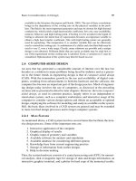
applying force and press machines are good examples of this. In addition, robot sys-
tems (Fig. 1.1a) for welding, cutting, and painting can be included in a broad sense.
When NC machines were developed, the purpose of the NC machine was to ma-
chine parts with complex shape in a precise manner. Therefore, the numerical con-
troller was primarily applied to milling machines (Fig. 1.1b) and boring machines.
However, recently it has become popular to apply NC for increased productivity and
the kinds of machine with NC have been varied to include machines such as turning
machines (Fig. 1.1c), machining centers (Fig. 1.1d), and drill/tapping machines. Par-
ticularly, the application of NC has extended to non-conventionalmachine tools such
as wire electro-discharge machines (Fig. 1.1e) and laser cutting machines in addition
to conventional metal-cutting machines.
3
4 1 Introduction to NC Systems
Also, as factory automation has progressed, NC machine technology has also pro-
gressed to allow construction of Flexible Automation(FA) or Flexible Manufacturing
Systems (FMS) (Fig. 1.1f) by connecting machines with production equipment such
as robots, AutonomousGuided Vehicles (AGV), automated warehouses and comput-
ers. NC systems are used not only for machine tools but also all machines that need
motion controlled by servo systems, such as cutting machines, drawing instruments,
woodworking machines, Coordinate Measurement Machines (CMM) and embroi-
dering machines and NC is the fundamental technology for factory automation.
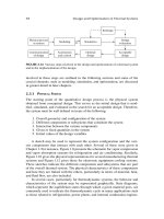
The task flow that is needed for producing a part using an NC machine can be
summarized as Fig. 1.2. The tasks can be classified as the following three types:
1. Offline tasks: CAD, CAPP, CAM
2. Online tasks: NC machining, monitoring and On-Machine Measurement.
3. Post-line tasks: Computer-Aided Inspection (CAI), post-operation
Offline tasks are the tasks that are needed to generate a part program for control-
ling an NC machine. In the offline stage, after the shape of a part has been decided,
a geometry model of this part is created by 2D or 3D CAD. In general, CAD means
Computer Aided Design but CAD in this book is regarded as a modeling stage in
which both design and analysis are included because engineering analysis of a part
cannot be carried out on the shopfloor.
After finishing geometric modeling, Computer Aided Process Planning, CAPP, is
carried out where necessary information for machining is generated. In this stage, the
selection of machine tools, tools, jig and fixture, decisions about cutting conditions,
scheduling and machining sequences are created. Because process planning is very
complicated and CAPP is immature with respect to technology, process planning
generally depends on the know-how of a process planner.
CAM (Computer Aided Manufacturing) is executed in the final stage for gen-
erating a part program. In this stage, tool paths are generated based on geometry
information from CAD and machining information from CAPP. During tool path
generation, interferences between tool and workpiece, minimization of machining
time and tool change, and machine performance are considered. In particular, CAM
is an essential tool to generate 2.5D or 3D toolpaths for machine tools with more
than three axes.
Online tasks are those that are needed to machine parts using NC machines. A
part program, being the machine-understandable instructions, can be generated in
the above-mentioned offline stage and part programs for a simple part can be di-
rectly edited in NC by the user. In this stage, the NC system reads and interprets part
programs from memory and controls the movement of axes. The NC system gen-
erates instructions for position and velocity control based on the part program and
servo motors are controlled based on the instructions generated. As the rotation of
a servo motor is transformed into linear movement via ball-screw mechanisms, the
workpiece or tool is moved and, finally, the part is machined by these movements.
To increase the machining accuracy, not only the accuracy of the servo motor,
table guide, ball screw and spindle but also the rigidity of the machine construc-
1.1 Introduction 5
(c)
(d)
(e)
(f)
Fig. 1.1 Types of NC machine (a) Robot, (b) Milling Machine (c) Turning machine (d) Machining
Center (e) Wire EDM (f) FMS Line
(b)
(a)
6 1 Introduction to NC Systems
tion should be high. The construction of the machine and the machine components
should also be designed to be insensitive to vibration and temperature. In addition,
the performance of the encoder and sensors that are included in the NC system and
the control mechanism influences the machining accuracy. The control mechanism
will be addressed in more detail in the following section.
In the online stage, the status of the machine and machining process may be mon-
itored during machining. Actually, tool-breakage detection, compensation of thermal
deformation, adaptive control, and compensation of tool deflection based on moni-
toring of cutting force, heat, and electric current are applied during machining. On-
Machine Measurement is also used to calculate machining error by inspecting the
finished part on the machine, returning machining errors to NC to carry out compen-
sation.
The post-line task is to carry out CAI (Computer Aided Inspection), inspecting
the finished part. In this stage, inspection using a CMM (Coordinate Measurement
Machine) is used to make a comparison between the result and the geometry model
in order to perform compensation. The compensation is executed by modifying tool
compensation or by doing post-operations such as re-machining and grinding. Re-
verse engineering, meaning that the shape of the part is measured and a geometric
model based on the measured data is generated, is included in this stage.
As mentioned above, through three stages, it is possible for machine tools not
only to satisfy high accuracy and productivitybut also to machine parts with complex
shape as well as simple shapes. Because NC machines can machine a variety of parts
by changing the part program and repetitively machine the same part shape by storing
part programs, NC machines can be used for general purposes.
In this book, the functionalities and the components of NC in the online stage
will mainly be addressed. However, considering that part of the CAM function has
recently been included in the online stage, WOP (Workshop Oriented Programming)
or SFP (Shop Floor Programming), which are types of online CAM systems, will be
described in detail.
1.2 The History of NC and NC Machine Tools
As mentioned in the previous section, the NC is the system that enables machine
tools to machine parts with various shapes rapidly and precisely. In NC, the servo
motor is used for controlling the machine tool according to the operation of a user
and a servo motor drive mechanism for activating the servo motor. That is, NC means
a control device that machines a target part by activating the servo motor according to
commands. The NC combined with computer technology is called computerized NC
or CNC (Computer Numerical Control). An NC machine which consists of vacuum
tubes, transistors, circuits, logic elements such as large-scale integrated circuits (LSI)
is called “Hardwired NC”, and performs NC functions through connecting elements
by electrical wiring. Instead of elements and circuits, NC functions are implemented
based on software in CNC. That is, this change from hardwired NC to CNC was
1.2 The History of NC and NC Machine Tools 7
Desired
shape
CAD
What to make
(Desired shape)
1. Computer
2. 2D Draft
3. Clay model
CAPP
How to make
(Which)
1. Machine
2. Tool
3. Process
4. Cutting condition
CAM
Tool-path
generation
Part P/G
NC Code
CNC board
Driver
Full-closed loop
Semi-closed loop
Motor
Encoder
Encoder
Linear
scale
Tool
Touch
probe
On-machine
measurement
Machine table
On-line
= ?
CMM
Post-line
Finishing
Off-line
Workpiece
Final
product
Ball
screw
Fig. 1.2 The architecture of NC machine tools and machining operation flow
driven by the advance in capacity and availability of microprocessors and memory.
Such CNC is called “Softwired NC”.
Through observing the advancement of NC, the fact that NC has the same devel-
opment history as its components can be seen. In the beginning, the pulse division
circuit was made from the computer with tens of thousands of vacuum tubes and
the machine tool was controlled by activating an oil-pressure motor and controlling
a relay according to the result of logical processing. However, as semiconductors
appeared and were applied to NC during the 1960s, electrical motors and power el-
ements during the 1970s and PC components during the 1980s, so Hardwired NC
evolved into a Softwired NC machine based on micro processors, electric power and
electronic technology, and software technology.
Now, NC and CNC mean Numerical Controller and there is no difference between
them. Therefore, NC machine means a machine tool with a CNC system.
It is known that the general-purposemanual machine tool was introduced after the
steam engine was developed in the late 18th century. Thereafter, Jacquard invented
the method of automatic control of the weaving of fabrics with a loom machine by
using punch cards and this method was the beginning of the concept of NC. The
concept of NC was actually applied to machine tools after World War II and in 1947,
the United States Air force and the Parsons company developed the method almost
simultaneously for moving two axes by using punch cards including coordinate data
to machine aircraft parts. Since then, this technology was transferred to the servo