Theory and Design of CNC Systems Part 8 ppsx
Bạn đang xem bản rút gọn của tài liệu. Xem và tải ngay bản đầy đủ của tài liệu tại đây (1.26 MB, 35 trang )
232 7 Programmable Logic Control
Output Unit, and the output signal converter amplifies the output signal of the CPU to
activate the external device. Further, the output signal terminal is used for connecting
the PLC system and external devices. In addition, the Output Unit includes a circuit
to prevent excessive current due to short circuits in the output signal terminal.
The CPU Unit is the core module of the PLC system, executing logic calculation
and arithmetic calculation by interpreting the PLC program and the final results are
sent to the Output Unit. In other words, the CPU Unit handles the serial or parallel
sequence logic operations (e.g. AND, OR, and NOT), timer or counter operations that
are used for controlling the elapsed time based on an internal pulse counter, the four
arithmetical operations, the comparison operation, junction operations (e.g. JUMP
and CALL), mathematical function operations (e.g. COS, SIN, TAN, and Square
root), data transmission, and code conversion.
Program Memory, which stores the user programs, and System Memory, which
stores system data, OS, and application S/W, can be rewritable and can keep the data
using an internal battery even in the case of power failure.
In addition, auxiliary units such as the programming tool and interface units for
RS-232C serial communication and ethernet communication are included in the PLC
system.
Therefore, the maximum input/output contact points, the speed of the CPU Unit
(in FANUC, this is defined as the time consumption per step), the size of the Program
Memory (in FANUC, this is defined as the maximum number of steps.), the kinds
of commands, and the kinds of allowable external communications are specified to
represent the performance of the PLC system.
The method of executing the command specified in a program is as follows.
A PLC programmer creates, edits and saves the PLC program by utilizing a pro-
gramming language such as the ladder diagram, instruction list, etc.
After saving the PLC program, the PLC system scans and executes the steps from
first to last. Accordingly, the PLC system generates the output signal by execution of
the program sequence every specified time period.
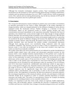
As shown in Fig. 7.2, an internal interpreter takes one command from the part pro-
gram in Program Memory and interprets the command. The interpreted command is
executed by calling the appropriate built-in function. In the process of interpretation,
bits of an address in the PLC program are read, and the corresponding address bits
are set to ON or OFF.
The above-mentioned method is an interpretative method whereby the interpre-
tation and execution of steps is repeated one by one while logic control is per-
formed. Because an interpreter-type PLC system reads and interprets the individ-
ual native code of a program sequence and performs the pre-specified macro routine
related with the native code, reduction of execution speed cannot be avoided. Fur-
thermore, because various subroutines for handling internal commands are included
in an interpreter-type PLC system, calling subroutines and returning results occur
frequently during the execution of a sequence program.
In general, the elapsed time for one scan is very important for the performance of
PLC system. Therefore, in order to overcome the slow speed and inefficiency of the
interpretative method, a more efficient and faster method is required.
7.2 PLC Elements 233
Program memory
Input memory
RD X0.0
AND R25.0
OR X7.1
ANDN R27.0
WRT Y48.0
END
Decoder
Executing
Internal
Command
X0.0
X7.1
Output memory
Y48.0
R25.0
R27.0
Intern Relay
Fig. 7.2 Operation of internal interpreter
The compiling method was introduced to overcome the disadvantages of the inter-
pretative method and the behavior of the compiling method is shown in Fig. 7.3. In
the compiling method, a program sequence is interpreted in advance and the internal
commands are replaced with pre-specified routines. Jumps and returns are omitted
during logic control and the execution speed can be increased.
PLC
Program
Internal
Command
Converter
Compiler
Assembler
PLC
Memory
Fig. 7.3 Behavior of compiling method
The workflow of the compiling method can be summarized as follows:
1. The PLC programmer edits a sequence program using a programming tool, which
can exist outside or inside the PLC system.
2. The sequence program is converted to a native program with internal commands
by the Internal Command Converter.
234 7 Programmable Logic Control
3. The compiler replaces the internal commands with the appropriate pre-defined
assembly codes.
4. The assembler converts the assembly code into the machine language (binary
code) which can be executed by the CPU. Because the majority of commands
in a PLC program are independent from each other it is possible to save mem-
ory and increase interpretation speed if commands are handled one by one in the
assembler after the labels and variables relevant to multiple steps (blocks) have
been handled.
5. Finally, the native code is transmitted to the internal memory when the PLC is
idle. It is then executed sequentially.
In consequence, the PLC program edited by a programmer is converted to an
executable binary code by a compiler and is sent to the PLC memory. Fast scanning
becomes possible compared with the interpretation method.
7.3 PLC Programming
There are a variety of the programming languages to represent logic sequences and
the IEC (International Electrical Committee) classifies the programming language
into the statement list representation and the graphical representation.
As the graphical language, there is the ladder logic that is a method of draw-
ing electrical logic schematics. As the statement list (textual) language, there are
mnemonic language, Boolean language, and machine language. In practice, the lad-
der logic, which can be easily mapped with a sequence logic drawing, has been
widely used. Figure 7.4 shows a ladder diagram and a mnemonic program that has
same meaning as the ladder diagram.
Because the symbols and commands used in ladder logic and mnemonic language
are slightly different, depending on the makers, it is essential to edit new programs
when the PLC system is changed.
Table 7.2 shows the mnemonic symbols of the basic and advanced command sets
(e.g. timer/counter function, control function and register manipulation function) for
Yasnac’s PLC programming.
In a typical PLC program, basic commands such as LD, LD-NOT, AND, AND-
NOT, OR, OR-NOT, and OUT are widely used. The Timer function, which sets the
output port as ON or OFF after a pre-determined time, is widely used. Basically,
the Timer measures the specified time by counting the time-based pulses generated
every constant time interval and multiplying the number of pulses counted by the
sampling time for pulse generation. The Timer sets the output port as ON of OFF
after the specified time. According to the PLC system, the sampling time of pulse
generation can be set as 10 ms, 100 ms, and 1 s. The Timer can be classified as one
of two types: an UP-timer, which counts the incremental time to the specified time, or
a DOWN-timer, which counts downwards with decremental time from the specified
time.
7.4 Machine Tool PLC Programming 235
Ladder diagram
Mnemonic langeuage
1
2
3
4
5
6
7
8
9
10
RD
ANDN
RDS
AND
ORS
WR
RD
ANDN
WRN
END
X0.1 Y2.1
Y4.3
Y0.1
X1.1
F0.1
X7.7
G0.1
END
X0.1
Y2.1
Y0.1
X1.1
Y4.3
F0.1
X7.7
G0.1
Fig. 7.4 Ladder diagram and mnemonic program
A Counter is used for counting time like the Timer. However, unlike the Timer,
the Counter uses an external input signal, whereas the Timer uses the internal time
base pulse for counting time.
Unlike the initial PLC systems, which enabled the fundamental logical opera-
tions, a modern PLC system can perform the four arithmetical operations of BCD
values, conversion between decimal and hexadecimal values, branching operations
(e.g. JUMP and CALL), and trigonometrical functions and special functions for ad-
vanced control.
Editing PLC programs is outside the scope of this book. If you want more infor-
mation about PLCs, refer to the related books on PLC.
7.4 Machine Tool PLC Programming
The PLC system of a CNC machine tool executes not only M-, T- and S-codes spec-
ified in a part program but also activates or inactivates external switches, executing
the PLC program together with input signals from the sensors in machine tools.
Therefore, when we create a PLC program for a CNC machine tool, special con-
siderations are necessary compared with the general PLC system. However, from a
functional point of view, the two types of PLC system are not different.
The role and characteristics of a PLC program in a machine tool are summarized
as follows:
1. The PLC program sends the status of the operation panel to the NCK and shows
the status of the NCK to the operator via the operation panel.
236 7 Programmable Logic Control
Table 7.2 Basic commands and functional commands for PLC programming
Type Instruction Meaning
LD Regular contact used in beginning of step.
LD-NOT ‘Not’ contact used in beginning of step.
AND Regular contact that represents the serial
connection in Ladder diagram.
AND-NOT ‘Not’ contact that represents the serial
connection.
OR Regular contact that represents the
parallel connection.
OR-NOT ‘Not’ contact that represents the
parallel connection.
Basic XOR Exclusive OR.
command XNR Exclusive AND.
STR After storing the operation result on
stack, perform LD command.
STR-NOT After storing the operation result on
stack, perform LD-NOT command.
AND-STR Operation result AND the value on stack.
OR-STR Operation result OR the value on stack.
OUT Ouput the operation result.
Timer TIM Fixed timer.
TMR Variable timer.
NOP No action.
Control MCR If input condition is ON, the program
is performed until END.
command END Represents the end of MCR command.
RET Represents the end of PLC program.
RTI If input condition is ON, perform RET
command.
SET Set ON.
RTH Rep. end of high-speed PLC program.
JMP Jump to the number specified by ADR.
ADR Specify the number to which is jumped
by the JMP command.
INR Increase the value in register by one.
Register DCR Decrease the value in register by one.
command CLR Reset the register.
CMR Reverse the register
ADI Add value of register to the specified
value.
i. The operator changes the machine operation mode (e.g. Auto mode, MDI
mode, and Zero Return mode) by turning on or off switches on the operation
panel. The change of machine operation mode is sent to the NCK by a PLC
program.
ii. The operator controls the axis’ movement, such as JOG, cycle start, or
emergency stop by turning on or off switches on the operation panel.
iii. By turning on or off the LEDs and lamps on the operation panel, the PLC
program displays the execution status of a part program.
7.4 Machine Tool PLC Programming 237
2. Through interaction with the NCK, a PLC program helps the execution of a part
program.
i. A PLC program prevents execution of the next block until the execution of
an M-code is completed.
ii. PLC program prevents execution of the next block until the spindle speed
reaches the value specified by an S-code.
iii. The PLC program prevents execution of the next block until the tool spec-
ified by a T-code has been attached to the spindle.
3. A PLC program provides various interlock functions to prevent the operator and
the workpiece being damaged.
i. It prohibits rotation of the spindle in the case of the chuck being unclamped.
ii. It stops axis movement as soon as the spindle is stopped.
iii. It changes operation mode to single block mode when the coolant’s motor
is overheated.
The general procedure for editing a PLC program is follows:
1. Assign addresses to the input and output ports,
2. Assign addresses to the internal relays and counters,
3. Design the sequence circuit to enable the intended logical operation based on the
assigned addresses,
4. Select the appropriate programming language and edit the PLC program in the
selected language,
5. Load the PLC program to the CPU module and carry out debugging.
The first step for editing a PLC program for a machine tool is to assign addresses
to the input and output ports. The address means the connection point for transmitting
the signal from/to the machine tool, CNC, relay, timer, counter, and data table. The
type, transmitting direction, and reserved address for PLC programming are shown
in Fig. 7.5. In the PLC shown in Fig. 7.5, the X address denotes the input signal
transmitted from the machine to the PLC and the Y address denotes the output signal
transmitted from the PLC to the machine. It is assumed that the number of input
signals and output signals are both 64. ‘G’, ‘F’, and ‘R’ are used to represent the
signal output from the PLC to the CNC, the input from the CNC to the PLC, and
the internal relay. In addition, 16 32-bit timers and counters are defined and the 2048
bytes are allocated to the internal memory.
According to the addresses assigned in Fig. 7.5, the address definition for PLC
programming is partially shown in Fig. 7.6.
After assigning the addresses, the sequence flow is designed and programming
is performed as described in the sequence flow. Figure 7.7 shows an example of a
typical sequence flow for a 3-axis machining center. The following addresses how to
design the sequence flow of a PLC program.
1. The first thing at the beginning of a program is to check the condition of the
emergency stop.
238 7 Programmable Logic Control
Internal Data Memory
Internal Timer
Internal Counter
Internal Relay
CNC
PLC
M/C
Signal Address and Directions
G
D
X
F
Y
T, C, R
Add.
X
Y
G
F
R
T
C
D
Signal
Direction
Example
Notation
Input from M/C to PLC
Output from PLC to M/C
Output from PLC to CNC
Input from CNC to PLC
Internal Relay
Internal Timer
Internal Counter
Internal Memory
64 points
64 points
256 points
256 points
512 points
512 byte
512 byte
2048 byte
(X0.0 ~ X7.7)
(Y0.0 ~ Y7.7))
(G0.0 ~ G31.7)
(F0.0 ~ F31.7)
(R0.0 ~ R73.7)
(32bit timer * 16)
(32bit counter * 16)
(32bit data * 64)
Fig. 7.5 Type, transmitting direction, and reserved address for PLC programming
2. Next is to design a sequence flow to handle an axis operation and transformation
mode input from the user interface panel.
3. After step 2, the processes for handling T, S, and M codes are designed. For the T-
code operation, the control flow related to the tool magazine rotation, tool change
mechanism, spare tool management, turret rotation of a lathe, etc. should be con-
sidered. Several subroutines are essential for magazine operation of the machining
center, as examples are 1) a rotational direction decision for the shortest distance
based on the current tool position, 2) an ACC/DEC control for smooth rotation of
the magazine, and 3) interrupt handling for high-speed rotation of the magazine,
etc.
4. In the case of an S-code, the essential subroutines for spindle operation are rela-
tively simple. Examples of necessary subroutines are 1) generation of a spindle-
enable signal, 2) generation of a rotation direction (CCW or CW) signal, and 3)
checking whether rotational speed is as commanded by communication with the
NCK system, etc.
5. For handling of M-codes, the machine-specific sequence flow should be designed
including M03 (Spindle CW), M04 (Spindle CCW), M05 (Spindle stop), M08
(Supply the cutting fluid), M09 (Stop supplying the cutting fluid). However, it is
not necessary to design the conventional M-codes commonly interpreted by all
types of machine, such as M00 (Program stop temporarily), M01 (Program stop
if an optional stop button is pressed), M02 (Program end), and M30 (Program end
and repeat) because the NCK system is handled in the normal CNC system.
6. Finally, the processes for turning on the ramps and displaying the messages for
the user interface are designed.
7.4 Machine Tool PLC Programming 239
X00.0 MPG Selection
F05.0
CNC Ready
X00.1
X00.2
X00.3
X00.4
X00.5
X00.6
X00.7
X01.0
X01.1
X01.2
X01.3
X01.4
X01.5
X01.6
X01.7
X02.0
X02.1
X02.2
X02.3
X02.4
X02.5
X02.6
X02.7
+X axis Jog
- X axis Jog
+Y axis Jog
- Y axis Jog
+Z axis Jog
- Z axis Jog
Rapid
Emergency Stop
+X axis Limit
- X axis Limit
+Y axis Limit
- Y axis Limit
+Z axis Jog
- Z axis Jog
Over-travel Cancel
Edit Lock
Cycle Start
Feed Hold
Chuck Switch
Auto Door
Bar Feeder FW
Bar Feeder BW
Door Interlock
Y00.0
Y00.1
Y00.2
Y00.3
Y00.4
Y00.5
Y00.6
Y00.7
Y01.0
Y01.1
Y01.2
Y01.3
Y01.4
Y01.5
Y01.6
Y01.7
Y02.0
Y02.1
Y02.2
Y02.3
Y02.4
Y02.5
Y02.6
Y02.7
Spindle CW
Spindle CCW
Chuck Clamp
Chuck Unlamp
Servo(on/off)
Hybraulic Motor
Lubrication Motor
Work Light
Program End
+X axis Lamp
- X axis Lamp
+Y axis Lamp
- Y axis Lamp
+Z axis Lamp
- Z axis Lamp
Cycle Start Lamp
Feed Hold Lamp
Machine Lock
Coolant Auto Lamp
Coolant Run Lamp
Coolnat Stop Lamp
Run Lamp
Alarm Lamp
Spindle CW Lamp
F05.1
F05.2
F05.3
F05.4
F05.5
F05.6
F05.7
F07.0
F07.1
F07.2
F07.3
F07.4
F07.5v
G03.0
G03.1
G03.2
G03.3
G03.4
G03.5
G03.6
G03.7
G04.0
G04.1
CNC Mode Auto
CNC Mode Manual
CNC Mode MDI
Reset
CNC Alarm
Ref retrun-X axis
Ref return-Y axis
Ref return-Z axis
Dry Run
Machine Lock
Optional Stop
Optional Block Skip
Spindle Orient
PLC Ready
Emergency Stop
MPG Selection
PLC Alarm
Rapid
Overtravel Cancel
Cycle Start
Free Hold
Spindle CW
Spindle CW
*
*
*
Fig. 7.6 PLC programming signal definition (partial)
As can be seen from the above programming procedure, third parties have diffi-
culty in understanding the PLC program without detailed descriptions and sequence
charts. Also, re-programming is needed to add and modify other functions. Due to
the absence of a standardized programming language, a programmer must know a
variety of languages depending on different PLC systems and makers. This makes
the training of a programmer and the maintenance of the PLC system difficult.
240 7 Programmable Logic Control
Start
Check E-Sstop
condition
Set operation
mode
Set feed mode
Read T code
Read magazine
position
Check rotational
direction of
magazine
Set deceleration
range of
magazine
Stop rotating
magazine
Check the
rotation
condition of
spindle
Command
spindle
Check
commanded
speed of spindle
Read M code
Process M code
Check the end
of M/S/T
process
Turn on lamps
in MMI panel
Display
messages
End
Additioanl
interrupt
subroutine is
programmed, if
high speed
rotation of
magazine is
required
Fig. 7.7 Typical 3-axis machining center sequence flow
7.5 PLC System Functions
In order to establish Factory Automation, enabling cost reduction, unmanned oper-
ation, and quality improvement, it is essential to build a network system to connect
various automation units (e.g. CNC machine tools, FA robots, PLCs, sensors and
actuators) and the production management system (e.g., MRP system and POP sys-
tem).
Among these, the importance of the PLC, which is applied to various areas, has
been emphasized, not only as the logic controller but also as the core technology for
building FA systems. Therefore, as functions of the PLC, advanced control functions,
a user-friendly interface, and network interface functions for communication with
sensors and management systems are required.
However, the PLC system is generally a closed system and depends highly on the
maker’s own technology. This means that the user can use only the functions pro-
vided by the maker and the user’s own technology and functions cannot be applied.
Because of this, whenever the PLC system is changed, the user should be re-trained
and the PLC program should be re-programmed. To solve the above-mentionedprob-
lem, compatibility and openness of PLC system are necessary. For this, the PLC
7.5 PLC System Functions 241
system has advanced to become an open PLC system that can meet the following
requirements:
1. Portability: The PLC program can be operated and is reusable regardless of PLC
system and maker.
2. Connectivity: Communication (data transmission) between PLC systems whose
makers are different should be guaranteed.
3. Standardization: The user interface and programming language are unified regard-
less of system and maker.
For example, the PLC systems and programming languages mentioned in previ-
ous sections are not compatible with other systems and languages that other makers
provide. Therefore, users should learn the maker’s own programming languages. It
is also very difficult for third parties to understand and modify PLC programs. In ad-
dition, when a new function is added, it is almost impossible to guarantee successful
execution within a specified time.
To overcome these problems, the activity for standardizing programming envi-
ronments for industrial automation equipment was started and the IEC, (Interna-
tional Electrotechnical Commission), established IEC1131-3 in 1993. The standard
IEC1131, is the international standard for PLC, consisting of five parts and IEC1131-
3 is one of the parts of which IEC1131 is composed.
1. IEC1131-1: PLC General information.
2. IEC1131-2: Equipment and test requirements
3. IEC1131-3: PLC programming language
4. IEC1131-4: User guidelines
5. IEC1131-5: Communications
IEC1131-3 is the international standard for programmable controller program-
ming languages. It specifies the syntax, semantics and display for the following suite
of PLC programming languages: 1) Ladder diagram (LD), 2) Sequential Function
Charts (SFC), 3) Function Block Diagram (FBD), 4) Structured Text (ST), and 5)
Instruction List (IL).
If we use IEC1131-3 to edit a PLC program, it is possible to obtain the following
advantages:
1. Because syntax and semantics are unified, it is possible to generate a program
that can be operated on all makers’ systems and the program can be executed
regardless of maker.
2. It is easy to maintain the program.
3. Because the standard supports the structured programming method, any complex
program can be edited in easily understandable and structured format and can
easily be maintained.
4. Due to the rigorous syntax and semantics it is possible to reduce program error.
5. The standard makes modularization of a program easy and it is possible to in-
crease the efficiency of programming using program modules.
242 7 Programmable Logic Control
However, the following disadvantages have been identified:
1. Compared with the sequence programming method, the programming procedure
is complex due to computer programming.
2. Much effort is needed to understand and know the grammar of the programming
language.
3. Due to the rigorous grammar, the flexibility of programming is restricted.
4. Because IEC1131-3 is heavy, it is not appropriate for application in small-sized
PLC systems.
IEC1131-3 consists of the configuration model of a PLC system, five program-
ming languages, and the common generality of programming languages.
The software model and communication model address the name and definition
of the parts from which a PLC system is composed and the data transmission mecha-
nism between running programs. In the Programming model, not only basic elements
such as identifiers, keywords, data types, and variables but also program elements
such as functions, function blocks, programs, resources, and tasks are described as
the common factors of the programming language.
To understand IEC1131-3, it is necessary to undertake a study of the configuration
model, which represents the design concept of a PLC system and includes a software
model, communication model, and programming model.
7.5.1 Software Model and Communication Model
In the introductory part of IEC1131-3 the software model is described and represents
the PLC system as a controller with multitasking-enabled architecture, as shown in
Fig. 7.8.
In the software model,
1. Configuration is the top-most concept that represents the PLC system and includes
all the software that is contained in one PLC system.
2. Resource is the element that makes up the configuration and means the functions
that a processor board provides. It consists of the software that is needed to exe-
cute a PLC program.
3. Program means the logical management unit of a user program and is edited by
one of the languages specified by IEC1131-3.
4. Function block is a key concept of IEC1131-3 and makes a program structured
and modularized. It is the logical management unit for data transmission and con-
sists of the data for defining input/output parameters and the algorithms for per-
forming specific functions.
5. Task represents how a program or function block works. It begins iteratively or
by a specific trigger.
7.5 PLC System Functions 243
Configuration
Resource
Task
Task
Program
Program
FB
FB
Resource
Task
Task
Program
Program
FB
FB
Access Paths
Global and Direct Variables
Variables FB Runction Blocks Access paths
Fig. 7.8 IEC1131-3 Software Model
6. Function is one of the elements of which a program is composed. It is different
from the function block, and it denotes the software that generates a single output
from a specific input.
7. Access path does not exist in a single resource system. In multiple resource sys-
tems it manages the data of elements and the communication between elements.
There are various ways to transmit data in a PLC system. In a program, internal
variables are used. To input and output the data to the program, function, and
function block, input variables and output variables are used. To share resource
or configuration information between programs, external variables that specify
them are used. In addition, data transmission between configurations is done by
the communication object defined by an access path. Using the access path, it is
possible to exchange data between the functions and the programs that are located
in different resources or configurations.
Comparing PLC systems with the software model in IEC-1131-3, we can regard
the controlled system as configuration. Configuration exchanges data or information
with other configurations via Access paths (only specific variables can be transmitted
via access paths and extended communication functions, as specified in IEC1131-5).
This configuration consists of one or multiple resources and each resource con-
sists of one or multiple tasks. Because of the high functionality of PLC systems,
multiple processing is required and the CPU board can be regarded as a resource.
Each task executes a program or function block based on regular interrupts or irreg-
ular triggers. Consequently, this systematic structure makes it possible to execute a
244 7 Programmable Logic Control
lot of individual programs synchronously. In addition, resource has a function for
supporting the interface between I/O channel and a program.
Furthermore, small-sized PLC systems consist of one processor and one piece
of software that controls single operations. A single configuration is formed, even
in the case of large-sized PLC systems with multiple processors, a variety of re-
sources (multiple processors) are controlled in real-time. In the case of complicated
distributed systems, a system is composed of more than one configuration connected
by a network and each configuration can include any resource or program on the
network.
As is known from the software model, the key concept of IEC1131-3 is to sup-
port the structured programming concept. Actually, by using the task, function, and
function block mentioned in the software model, it is possible to change the pro-
gramming style of the user. Therefore, by using IEC1131-3 it is possible to design
a PLC system by distinguishing an iterative task and an interrupt-driven task (or
event-driven task). Furthermore, it is possible to divide the iterative tasks into tasks
with the same iteration time. In addition, by implementing common tasks or pro-
grams as functions or function blocks, it is possible to decrease the program size.
Consequently, this structured programming method enables the modularization of
programs and this modularization increases the productivity and maintainability of
large-sized PLC systems.
7.5.2 Programming Model
The programming model describes the relationship between the common elements
of the programming language specified in IEC1131-3. The programming model is
based on the concept of derivation and reuse. In other words, the programmer can
define new data types from basic data types, new functions or function blocks from
basic functions (or standard functions) and can make libraries using them. These li-
braries can be used not only in an identical system but also in other non-identical sys-
tems. The reusability of programs enables advanced programming techniques such
as libraries, functions, and function blocks and provides ease and reliability of pro-
gramming.
As mentioned above, as IEC1131 is the international standard for PLC, it consists
of a configuration model and a programming model. To build the standard and open
system, it is necessary for the PLC system developer to design the system and the
functions based on IEC1131. It is also necessary to design the interpreter for the
standard programming language. As well as programmers or system designers, it
is also necessary for system users (operators) to understand the key concepts and
functions.
7.5 PLC System Functions 245
7.5.3 User Programming Languages
In IEC1131-3, five programming languages (actually, four languages and one com-
mon element) are specified; LD (Ladder Diagram), IL (Instruction List), ST (Struc-
tured Text), FBD (Function Block Diagram), and SFC (Sequential Function Chart).
The user can select the appropriate language depending on the characteristics of the
program.
Actually, SFC is not a programming language for implementing the control pro-
gram, but the representation tool to depict all sequences of a control program. As
shown in Fig. 7.9, SFC classifies continuous tasks into Steps as well as Transitions,
which are the conditions for shifting between steps, and Actions, being the job to be
performed at a step.
In other words, SFC is composed of multiple steps, the module of a program, an
action block associated with a particular step, and a transition to represent the con-
dition for shifting between steps. This graphical representation method is based on
Petri-nets or IEC848. SFC can be used not only by itself but also with other program
languages specified in IEC1131-3. Therefore, SFC is used as a common element in
IEC1131-3. SFC supports not only conditional sequencing but also parallel sequenc-
ing where one sequence monitors or executes a background task simultaneously with
another performing the main control.
Step 1
Step 2
Step 3
Transition 1
Transition 2
N Action 1
S Action 1
Fig. 7.9 SFC continuous task classification
For effective programming, it is necessary to reuse functions or partial programs.
For this, functions, function blocks, and programs are reused in application pro-
grams. A function is composed of basic functions such as ADD, ABS, SQRT, SIN,
and COS and user-defined functions. A function block contains data and algorithms,
as semiconductor hardware, which enables the specific function. It can be reusable
in other application programs. In addition, Functions, function blocks, and programs
are common elements that can be used in all programming languages specified in
IEC1131-3.
Besides SFC, the possibility of powerful data addressing is another common el-
ement. It is used to prevent a programmer from substituting (allocating) a different
data type to a variable. Boolean type, integer type, byte type, word type, date type,
and date-time type are defined as the data types of IEC1131-3. Local variables and
global variables can be used as variables in IEC1131-3. A local variable is a variable
246 7 Programmable Logic Control
that can be used only within software elements where it is defined. Global variables
mean variables that can be used over whole software elements. It is also possible to
define direct pointer variables that refer directly to memory locations.
Objective:
I1.3
I1.3
If input port I 1.3 becomes ON, the output
port Q0.0 is Set
If input port I 3.1 becomes ON, the output
port Q0.0 is Reset
IL(instruction list) ST(structured text)
LD I 1.3
OR Q 0.0
ANDN I 3.1
OUT Q 0.0
IF I 1.3:= ON THEN
Q 0.0:=SET;
END-IF
IF I 3.1:=ON THEN
Q 0.0:=RESET;
END-IF
IL(instruction list)
ST(structured text)
Alarm_SR
I 1.3
I 3.1
S
R
Q
alarm
Alarm
I 1.3
I 3.1 Q 0.0
Q 0.0
Fig. 7.10 The PLC languages specified in IEC1131-3
The key characteristics of the four languages specified in IEC1131-3 are summa-
rized in Fig. 7.10 with the above-mentioned common elements. For convenience of
understanding, the program that sets or resets the output port depending on the type
of input is edited by four languages and the basic format of each language will be
described.
Among the four languages, IL (Instruction List) and ST (Structured Text) are tex-
tual languages, while the LD (Ladder Diagram) and FBD (Function Block Diagram)
are graphical languages.
1. IL, which is widely used in Europe, is a low-level language like assembler. The
advantage of IL is that it is adequate for small-sized programs thanks to simple se-
7.6 Soft PLC 247
quences and logic. It can be used for describing transitions in SFC with function,
function block, and program sequences.
2. As ST is a high-level language, it is related to Ada, Pascal, and C. By using ST, it
is possible to allocate values to variables and describe tasks by wiring functions,
function blocks, and program blocks. Conditional branching and iteration loops
are possible too. It can also be used to describe steps, action blocks, and transi-
tions. In addition, it is adequate for numerical calculation and defining complex
function blocks.
3. LD is a well-known language. A program is composed of a combination of input
and output contacts. LD is used not only for editing the control program but also
monitoring the output/input contacts while a program is being executed. In addi-
tion, with functions, function blocks, and programs, it can be used for describing
the results of transitions in SFC.
4. FBD is a graphic-based language. It is largely used for programming signal flow
between control blocks because of its easy understanding of the flow of a program.
FBD is similar to electric circuits including the signal flow of process control. It
can be used for describing the behavior by wiring functions, function blocks, and
program blocks and describing the step, action block, and transition in SFC.
7.6 Soft PLC
In the late 1960s, after GE powertrain introduced the concept of the PLC system that
replaced the relay board, PLC systems that control a variety of processes by using
simple sequence programs has been widely used for 40 years.
However, as the controlled systems have become more complex, faster, and larger,
the demand for openness and standardization of PLC systems has increased. To meet
this requirement, the PLC system has been changed from a hardware-based system
to a software-based system. Consequently, Soft PLC systems, which operate from
personal computers and enable logical sequence control functions in real time, were
introduced. With the advancement of the PCs performance, Soft PLC systems have
come to provide not only conventional sequence control functions but also easy user
interfaces, network communication functions, and advanced functions for factory
automation. In Soft PLC systems, the basic and advanced functions of PLC and
communication functions are executed by one processor module, except for input
and output modules. It is possible to make a standardized PLC system based on the
software model and programming languages specified in IEC1131-3.
Figure 7.11 shows an example of a Soft PLC that has been applied to the transfer
line in Ford Motors. In this system, the interface board that can be connected to
various I/O devices (e.g., AB1771, Seriplex, OPTO 22) is built into a PC that contains
the Soft PLC system. This system is a good example of a Soft PLC system that
satisfies the openness requirement by using PC hardware.
To develop a soft PLC system, real-time operation and reliability of response,
which are key requirements for industrial PLC systems, should be guaranteed. Ba-
248 7 Programmable Logic Control
Machining Station I
AB 1771 I/O
Machining Station II
AB 1771 I/O
Machining Station III
AB 1771 I/O
PC running Windows-NT
Soft PLC
Multi-I/O
Interface
Board
Fig. 7.11 Soft PLC automotive transfer line
sically, though, PC operating systems cannot satisfy these. However, the non real-
time property of DOS or Windows OS can be overcome by various methods and the
method of designing a soft PLC system will be described together with design of
Soft-NC in the later in this textbook. In Soft-NC, a PC is used as the hardware plat-
form and all CNC functions including PLC functions are implemented in software.
In this point, Soft PLC is very similar to Soft-NC. Furthermore, Soft NC includes
more functions than Soft PLC, used for NCK control and MMI. Therefore, if NCK
functions and MMI functions are omitted or simplified from Soft NC, Soft NC and
Soft PLC can be regarded as the same system. Soft PLC which is made by a user
interface and the PLC kernel based on the IEC1131-3 can be regarded as partial
systems of Soft-NC.
Figure 7.12 shows the open CNC system of MDSI. The figure shows that the CNC
system consists of Interpreter (NC Code Parser), Servo controller (Servo Algorithm),
Interpolator (Path/trajectory Planning) for NCK, user interface for MMI, Soft PLC
for PLC, and APIs for external users. This model shows that Soft PLC is one of
the software modules from which a CNC system is composed. If you want to know
more details about the hardware configuration and software of a Soft PLC, please
read other references about Soft-NC and Open CNC systems.
7.7 PLC Configuration Elements
In this section, the configuration and execution structure of a PLC system will be
addressed from the system designer’s point of view. Also, implementation of the
PLC program executor will be shown.
7.7 PLC Configuration Elements 249
User Interface
NC Code
Parser
Path
Planning
Servo
Algorithms
Trajectory
Planning
Significant
Events
Soft PLC
Real-
time
Database
UI
API
Utility
API
Real-time
API
Device Drivers
Encoders, DACs, I/O, Ethernet, SERCOS,
Firewire, Watchdog Timer, Prebing
To Machine
Fig. 7.12 Open CNC system of MDSI
7.7.1 PLC System Functions
The execution environment and main functions of a PLC system can be summarized
as in Fig. 7.13. The PLC program, which is interpreted and executed by the CPU
module, is edited by an external PLC programmer. The PLC programmer consists of
the editor module, compiler module, and communication module. The editor mod-
ule is used for editing the program, the compiler module is used for translating the
edited program into a CPU-understandable language, and the communication mod-
ule is used for transmitting the PLC program into the CPU module. In addition, the
monitoring module is used for sending the PLC status to the PLC programmer and
displaying the PLC status.
PLC Programmer
Editor
Compiler
PLC Monitor
Display
Reverse Conversion
Lexical
Analysis
Error
Check
Code
Conversion
Down Loading
Up Loading
CPU Module
Receive Machine Status &
Save at Machine Input Data Flag
Read PLC Program line by line &
Excute Logical operation
CPU & RAM -Data
Machine
Input
Data Flag
Machine
Output
Data Flag
Internal Relay
Internal Timer
Internal Counter
Save operation result
at Machine Output
Data Flag
Output Machine Outpit Data to the output module &
Start re-scanning
Input Module
Output Module
Fig. 7.13 Execution environment and main functions of a PLC system
250 7 Programmable Logic Control
The PLC programmer should have a program editor that provides an easy user-
interface and supports PLC programming languages such as Ladder, Mnemonic, and
Function block. The specification of the editor is given in IEC1131-3.
The PLC programmer can be implemented as one of two types; one is the ‘in-
terpreter type’ and the other is the ‘compiler type’. In the interpreter type, a native
program, which a user edits using some particular procedure, is interpreted line by
line and executed whenever it is needed. In the compiler type, a native program is
converted once to a CPU-understandable binary or hexadecimal file and, whenever
necessary, the compiled file is sent to the CPU module and executed.
Typically, a PLC programmer is implemented by the compiler type in order to
realize high-speed execution. Let’s see the procedure of a compiler. A compiler reads
one block of a native program line by line and divides the lines into elements from
which the block is composed.
As a sentence of a natural language consists of multiple words, a block of a pro-
gram is composed of tokens (e.g., constant values, variables, operators, and key-
words).
The compiler recognizes the tokens and finds the meaning of the words by analyz-
ing the tokens, syntax, and schema. The compiler searches for relationships between
tokens. The compiler generates intermediate code based on the previous result. The
compiler generates optimized code from the intermediate code for effective execu-
tion. Finally, it generates the instruction code.
A compiler is the software that converts a native program into CPU-understand-
able code. It provides the functions that transmit compiled code to the CPU module
and monitors the execution status of the PLC system.
The main task of the CPU module is to read and execute a binary program from
the PLC programmer. We call this module the ‘executor’ and how the CPU module
works is as follows. Firstly, the CPU module receives the machine status from the
input port and stores it to the machine input data flag. In the next step, it reads the
PLC program (binary code) line by line and carries out the logical operations. At
this moment, the internal relay, timer, counter, and input data flag are referenced.
The result from one line execution is saved to the machine output data flag and,
finally, the values from the machine output data flag are sent to the output port for
actuating the relay, solenoid, and user interface.
If one scan like that mentioned above has been completed, the executor repeats
the scan by reading the input ports (or address). Therefore, for designing the PLC
system, it is necessary to understand the behavior of this executor.
In Table 7.3, the set of PLC programming instruction is summarized together
with a description of the instruction set, mnemonic format, and function description.
This instruction set consists of the basic instruction set for the editing sequence and
the functional instruction set for describing tasks that are difficult to describe using
only basic instruction sets. The functional instruction set includes sequence control,
timer/counter, arithmetic operations.
7.7 PLC Configuration Elements 251
Table 7.3 PLC programming commands and functions
Command Mnemonic Function
Read RD X1.0 Read the specific address.
Read Not RND X2.1 Read the specific address and
reverse the value.
Write WR Y1.0 Write the operation result to the
specified address.
Write Not WRN Y2.0 Reverse the operation result and
write the reversed result to the
specified address.
And AND X3.2 Perform logical product between
the value of the specified address
and the value on the stack register
and store the result on the stack.
And Not ANDN Y0.2 Reverse the value of the specific
address, perform logical product
between the reversed value and
the value on the stack register, and
store the result on the stack.
Or OR Y2.7 Perform logical sum between the
value of the specified address and
the value on stack register and
store the result in stack.
Or Not ORN G2.1 Reverse the value of the specified
address, perform logical sum
between the reversed value and the
value on the stack register, and
store the result on the stack.
Read Stack RDS Y3.1 Shift the values of the stack to the
left and store the value of the
specified address in bit 0 of stack.
Read Not Stack RDNS R1.7 Shift the values of the stack to the
left and store the reversed value of
the specific address in bit 0 of
stack.
And Stack ANDS Perform logical product between
the values of the lower two bits,
save the result in the first bit of
stack, SR1, and shift the values
of stack to the right.
Or Stack ORS Perform logical sum between the
values of lower two bits, save the
result in the first bit of stack, SR1,
and shift the values of stack to the
right.
252 7 Programmable Logic Control
Table 7.3 (continued)
End of P/G END Terminate the program.
Timer TMR #5, 4000 When the input signal is ON, the
timer with specified number is exec-
uted during the specified time.
Counter CTR #1, 100 Whenever the input signal is
changed to ON from OFF, the
counter with the specified number
is actuated. When the count
reaches the specified number, the
counter output maintains ON status
before receiving the reset signal.
Move MOV 7, X1.2 Copy the left operand to the right
operand.
And Move ANDM 1, 3, When the input signal is ON, perf-
Y2.3 orms logical product between the
values of left operand and middle
operand and finally saves the res-
ult in the right operand.
Or Move ORM 3, 7, When the input signal is ON, perf-
X1.1 orms a logical sum between the
values of the left operand and the
middle operand and finally saves the
result in the right operand.
Call CALL Rosa When the input signal is ON, call
the subroutine with the specified
name.
Subroutine SBRT Stephy Start the sub routine.
Return RET Terminate the sub routine.
Jump JMP Khang When the input signal is ON, jump
to the program part starting with
the specified label.
Equal EQU 5, X1.0 When the input signal is ON, if the
value of the left operand and the
value of the right operand are equal,
set the specified bit as ON. Other-
wise, set the specified bit as OFF.
Greater Than GT Y1.1, 10 When the input signal is ON, if the
value of the left operand is greater
than that of the right operand, set
the specified bit as ON. Otherwise,
set the specified bit as OFF.
Less Than LT 10, X4.0 When the input signal is ON, if
the value of the left operand is less
than that of the right operand, set
the specified bit as ON. Otherwise,
set the specified bit as OFF.
7.7 PLC Configuration Elements 253
Table 7.3 (continued)
Shift Right SFTR X1.0,5 When the input signal is ON, shift
the value of the left operand to the
right as many bits as given by the
right operand.
Shift Left SFTL Y1.1, 3 When the input signal is ON, shift
the value of the left operand to the
left as many bits as given by the
right operand.
Addition ADD 1, 2, X1.7 When the input signal is ON, add
the values of the left operand and
the middle operand and store the
result to the right operand.
Subtraction SUB 3, 1, Y3.1 When the input signal is ON,
subtract the values of the left
operand and the middle operand
and store the result to the right
operand.
Multiply MUL2,5,X1.3 When the input signal is ON,
multiply the values of the left
operand and the middle operand
and store the result to the right
operand.
Division DIV 4, 2, Y2.2 When the input signal is ON, div-
ide the value of the left operand by
the value of the middle operand
and store the result to the right
operand.
Inverse INV X1.1, 5 When the input signal is ON,
reverse the bit of the address
specified by the left operand
as specified by the value of the
right operand.
Since the above functions denote how a sequence program (logic program) is
interpreted and executed in the program executor, an in-depth understanding of them
is needed to design a PLC program executor.
7.7.2 Executor Programming Sequence
To describe the sequence execution function of a PLC executor, let’s use the program
that was edited by the ladder diagram or mnemonic shown in Table 7.4.
The program that the user edited in a ladder diagram is converted into mnemonic
form to be executed by an interpreter-type executor. Alternatively, the user can edit
the program directly in mnemonic form. The executor that is designed in this text-
book handles the operations via a stack register. During execution of the mnemonic
program, the operation results are temporarily stored in a stack register and the op-
erations continue by using the values from the stack register. For example, the result
254 7 Programmable Logic Control
of the current operation is stored in SR0, the zero bit of the stack register. Through
continuous operations, the data in SR0 shifts to SR1 and a new value is stored on
SR0. Therefore, the previously stored value is shifted to the right and is saved by
the RDS command. To recall the value saved by the RDS, the ANDS command is
utilized.
As a practical example, when the executor performs the tasks from line number
10 to line number 30, the behavior of the executor is as follows.
1. The executor reads address X0.1 using the Read command and carries out the
logical operation and saves the the result of the operation in SR0.
2. It reverses the logic status of address Y2.1 and executes the AND operation (log-
ical product) between the serial-connected previous operation result and the re-
versed status of Y2.1. The operation result is saved in SR0.
3. To execute parallel-connected instructions, the value of SR0 is shifted to SR1
using the RDS command and the value of address Y0.1 is stored in SR0.
4. It executes the AND operation (logical product) between the value of address
X1.1 and the value of SR0 and the result is saved in SR0.
5. OR operation (logical sum) between SRB0 and SRB1 is executed and the result
is stored in SR0.
6. Finally, the value of SR0 is output to address Y4.3.
Subsequently, reading the status of the input port, executing the logical operation
by using the status via stack register and storing the result to the output port are
repeated.
7.7.3 Executor Implementation Example
In this section, a real implementation example of the executor capable of handling
the commands shown in Table 7.3 will be described. As an example, the programs
for the basic instruction sets are described. The programs for the functional instruc-
tion set including comparison function of the values of two registers, and the four
fundamental arithmetic operations can be achieved by extending the method shown
in the basic instruction cases.
7.7.3.1 Stack Register
The stack register saves the temporary operation result. It is assumed to be composed
of 16 bits as follows:
SR15 SR14
···
SR5 SR4 SR3 SR2 SR1 SR0
low end bit
✻
7.7 PLC Configuration Elements 255
Table 7.4 Comparison between Ladder diagram and mnemonic programming
Ladder diagram Mnemonic
In order to save the result of previous operation, the values of whole bits of the
stack register are shifted to the left. When the recall command is invoked for recalling
the stored value, the values of whole bits of the stack register are shifted to the right,
and the value shifted last comes first.
class CPLCStack
{
public:
CPLCStack();
virtual ∼CPLCStack();
private:
bool m
stack[STACKSIZE];
public:
void RD(char simbol, int upperadd, int loweradd);
void RDN(char symbol, int AddNum, int BitNum);
void WR(char symbol, int AddNum, int BitNum);
void WRN(char symbol, int AddNum, int BitNum);
void AND(char symbol, int AddNum, int BitNum);
void ANDN(char symbol, int AddNum, int BitNum);
void OR(char symbol, int AddNum, int BitNum);
void ORN(char symbol, int AddNum, int BitNum);
void RDS(char symbol, int AddNum, int BitNum);
256 7 Programmable Logic Control
void RDNS(char symbol, int AddNum, int BitNum);
void ANDS(char symbol, int AddNum, int BitNum);
void ORS(char symbol, int AddNum, int BitNum);
public:
void LShift(int i);
void RShift(int i);
};
void CPLCStack LShift(int i)
{
for(int j = STACKSIZE −1;j >= i;j −−)
m
stack[j] = m stack[j-i];
}
void CPLCStack::RShift(int i)
{
for(int j = 0;j < STACKSIZE−i;j ++)
m
stack[j] = m stack[j+i];
}
out one-bit operations and consist of twelve commands. To order basic commands
they are represented as follows:
(Command [Address name][Address number].[bit number]]
(Note that the ADNS and ORS commands are used without any arguments).
a) RD (READ)
• This command is to read the value of the specified address and save the value read
in SR0.
• It is used for A-type switch.
• Program structure
- Ladder Diagram
- Coding sheet and operation result
void CPLCStack::RD(char symbol, int AddNum, int BitNum)
7.7.3.2 Basic Command
The basic commands are mainly used for building the sequence program. They carry