Theory and Design of CNC Systems Part 13 pptx
Bạn đang xem bản rút gọn của tài liệu. Xem và tải ngay bản đầy đủ của tài liệu tại đây (1.38 MB, 35 trang )
408 11 STEP-NC System
(ABS)
Milling_type_operation
(ABS)Milling_machine_operation
(ABS)Machine_operation
(ABS)
Drilling_type_operation
(ABS)
Two5D_milling_operation
Freeform operation
(ABS) Plane_milling
(ABS) Side_milling
(ABS)
Bottom_and_side_milling
(ABS)
Drilling Operation
(ABS)
Boring_operation
Back_boring
Tapping
Thread_drilling
1
1
Part 11
Fig. 11.11 EXPRESS-G diagram for machining operation in Part 11
(ABS)
Two5D_milling_strategy
(ABS)
Freeform_strategy
(ABS)
Drilling_type_strategy
Bidirectional_contour
Contour_bidirectional
Center_milling
Undirectional_milling
Bidirectional_milling
Contour_parallel
Contour_spiral
Uv_strategy
Plane_cc_strategy
Plane_c1_strategy
Leading_line_strategy
11
Fig. 11.12 EXPRESS-G diagram for machining strategy in Part 11
11.4.5 Tools for Milling and Turning
This section deals with Part 111: “Tools for milling machines” and Part 121: “Tools
for turning machines”.
Part 111 and Part 121 define data elements describing cutting tool data for milling
machine tools and machining centers and for turning machine tools, respectively. In
ISO 6983, the tool is defined by its identifier (e.g. T8) and no further informationcon-
cerning the tool type or geometry is given. This information is part of the tool setup
sheet, which is supplied with the NC-program to the machine. However, ISO 14649
includes this information in the part program, such as tool identifier; tool type; tool
geometry; application-dependentexpected tool life. These data elements can be used
as criteria to select one of several operations; they do not describe complete informa-
tion of a particular tool. Therefore, leaving out optional attributes gives the controller
more freedom to select from a larger set of tools. Part 10 defines machining
tool as
11.4 STEP-NC Data Model 409
manufacturing_feature
transaction_feature two5_manufacturing_feature region
replicate_feature turning feature machining_feature compound_feature
knurl revolved_feature outer_round
straght_knurl
diagonal_knurl
diamond_knurl
catalogue_knurl
revolved flat
revolved_round
groove
general_revolution
outer_diameter
outer_diameter_
to_shoulder
1
1
1
1
1
1
Fig. 11.13 EXPRESS-G diagram for turning feature
(ABS)turning_machining_operation
(ABS)grooving
(ABS)facing
facing_rough
facing_finish
(ABS)contouring
contouring_rough
contouring_fihish
(ABS)threading
threading_rough
threading_finish
grooving_rough
grooving_finish
cutting_in
knurling
1
1
1
1
1
Fig. 11.14 EXPRESS-G diagram for turning machining operation
410 11 STEP-NC System
a supertype of milling machine cutting tools and turning machine cutting tools that
are defined in Part 111 and Part 121 respectively. Figures 11.15 and 11.16 show
the structure of the milling
machine cutting tool and turning machine cutting tool
elements.
(ABS)Machining_tool
its_cutting_edge SET[1:?]
Cutting_component
overall_assembly_length
(ABS)Milling_machine_
cutting_tool
effective_cutting_diameter
length_measure
maximum_depth_of_cut
hand_of_cut
Hand
BOOLEAN
Rotating_boring_cutting_tool
Drilling_cutting_tool
Reaming_cutting_tool
Tapping_cutting_tool
Milling_cutting_tool
Twist_drill
Counter_sink
Counter_bore
Spot_drill
Step_drill
Spade_drill
Shoulder_mill T_slot_mill Side_mill Thread_mill End_mill Dovetail_mill Face_mill
coolant_through_tool
1
1
Fig. 11.15 EXPRESS-G diagram for milling machine cutting tool
11.5 Part Programming
Based on the data model, the STEP-NC part program is represented as a physical file
according to ISO 10303 Part 21: Clear Text Encoding Rule. As shown in Fig. 11.18,
the STEP-NC part program is divided into the header section and the data section.
The header section includes information with regard to the part program itself, such
as the author information, schema information and version of the part program. The
data section includes all the information about the manufacturing such as process se-
quence, manufacturing feature, operation type, machining strategy, machining tech-
nology, machine function, workpiece and geometry. In this subsection, STEP-NC
part programs for milling and turning will be described.
11.5 Part Programming 411
machining_tool(Part 10)
(ABS)turning_machine_
cutting_tool
length_measure
length_measure
length_measure
length_measure
length_measure
2. 1. cutting_edge_properties
length_measure
[left, right, neutral]
general_turning_tool 3. 2.turning_threading_tool 3. 1.grooving_tool
3. 3.Knurling_tool 3. 4.user_defined_turning_tool
1
functional_length
f_dimension
minimum_cutting_diameter
a_dimension_on_f
a_dimension_on_lf
cutting_edge
hand_of_tool
Fig. 11.16 EXPRESS-G diagram for turning machine cutting tool
11.5.1 Part Programming for the Milling Operation
Figure 11.17 shows a simple example for milling, described in Annex E of ISO
14649 Part 11. Figure 11.18 shows the overall structure of the STEP-NC part pro-
gram for the test part of Fig. 11.17. Note that the part program of Fig. 11.18 is just
a fraction of the whole program in order to reduce space. For the full version of this
part program, please refer to Annex E of ISO 14649 Part 11.
The shape of Fig. 11.17 includes a plane at the top face (planar
face), a rect-
angular pocket (closed
pocket) and a hole (round hole). In this section, machining
sequences and detailed information about a rectangular pocket and its machining
operation will be explained.
“Sequences” noted in Fig. 11.18 shows information about the machining sequence
that is used to machine the test part. Every STEP-NC part program starts with the
project entity (#1). The main purposes of the project are to define the sequence of
machining processes by using the main
workplan (#2) attribute and to define the
workpiece information by using the workpiece (#4) attribute, which will be explained
later. In this example, five machining
workingsteps are executed sequentially. Firstly,
the finishing operation for the planar
face at the top (#10) is executed, and then
the drilling operation (#11) and reaming operation (#12) are executed sequentially
412 11 STEP-NC System
z
y
F1
1
z
x
y
P2
P1
F2
P3
P4
F3
x
20
25
50
100
30
50
30
80
120
R1
R10
Fig. 11.17 Simple example test part for milling
#1= PROJECT('EXECUTE EXAMPLE1',#2,(#4),$,$,$);
#2= WORKPLAN('MAIN WORKPLAN',(#10,#11,#12,#13,#14),$,#8,$);
#10= MACHINING_WORKINGSTEP('WS FINISH PLANAR FACE1',#62,#16,#19,
#11= MACHINING_WORKINGSTEP('WS DRILL HOLE1',#62,#17,#20,$);
#12= MACHINING_WORKINGSTEP('WS REAM HOLE1',#62,#17,#21,$);
#13= MACHINING_WORKINGSTEP('WS ROUGH POCKET1',#62,#18,#22,$);
#14= MACHINING_WORKINGSTEP('WS FINISH POCKET1',#62,#18,#23,$);
#18= CLOSED_POCKET('POCKET1',#4,(#22,#23),#84,#65,(),$,#27,#35,#37,#28);
#27= PLANAR_POCKET_BOTTOM_CONDITION();
#28= GENERAL_CLOSED_PROFILE($,#59);
#59= POLYLINE('CONTOUR OF POCKET1',(#121,#122,#123,#124,#121));
#22= BOTTOM_AND_SIDE_ROUGH_MILLING($,$,'ROUGH POCKET1',15.000,$,,#39,
#50,#41,$,#60,#61,#42,2.500,5.000,1.000,0.500);
#60= PLUNGE_RAMP($,45.000);
#61= PLUNGE_RAMP($,45.000);
#42= BIDIRECTIONAL_MILLING(5.000,.T.,#43,.LEFT.,$);
#41= MILLING_MACHINE_FUNCTIONS(.T.,$,$,.F.,$,(),.T.,$,$,());
#50= MILLING_TECHNOLOGY(0.040,.TCP.,$,12.000,$,.F.,.F.,.F.,$);
#29= TAPERED_ENDMILL(#30,4,$,.F.,$,$);
#30= MILLING_TOOL_DIMENSION(20.000,$,$,$,1.500,$,$);
#39= MILLING_CUTTING_TOOL('MILL 20MM',#29,(#125),80.000,$,$);
#4= WORKPIECE('SIMPLE WORKPIECE',#6,0.010,$,$,$,(#66,#67,#68,#69));
#6= MATERIAL('ST50','STEEL',(#7));
#7= PROPERTY_PARAMETER('E=200000N/M2');
#8= SETUP('SETUP1',#71,#62,(#9));
#9= WORKPIECE_SETUP(#4,#74,$,$,());
ISO-10303-21
HEADER;
ENDSEC;
DATA;
}
}
Sequences
Feature &
Geometry
Operation &
Technology
Tools
Workpiece
Data
Heade
r
Fig. 11.18 ISO 14649 part program for test part for milling
11.5 Part Programming 413
for the round hole. Finally roughing (#13) and finishing (#14) operations for the
closed
pocket are executed.
“Feature and geometry” shows feature information in the STEP-NC part program,
especially closed
pocket. In the part program, the bottom of the pocket is defined as
the planar
pocket bottom condition (#27). The general closed profile (#28), more
especially polyline (#59), is used for the contour of the closed
pocket.
Table 11.2 Process plan for the closed pocket
Closed pocket
machine parameter Bottom and side Bottom and side
rough milling finish milling
Tool Taper End mill 20.0 Taper End mill 6.0
Retract plane 30 30
ADC 4 1
RDC 3 1
Strategy bidirectional milling Contour bidirectional
Approach Plunge zigzag Plunge zigzag
Retract Plunge ramp Plunge ramp
Bottom allowance 1 0
Side allowance 1 0
Feedrate 250 250
Spindle speed 500 500
Coolant On on
Chip removal On on
Table 11.2 shows the process plan to remove the closed pocket of Fig. 11.17. In
this example, the part program for the roughing operation will be explained. Machin-
ing type is given by the bottom
and side rough milling entity (#22) that has axial
depth information (4.0), radial depth information (3.0) and finishing allowance for
the wall (1.0) and bottom (1.0), the starting point and the overcut length.
The machining
strategy defines the method to execute the given machining oper-
ation. The bidirectional
milling entity (#42) is used in the process plan of Table 11.2.
It defines the direction of the machining, step-overdirection and so on. If these values
are omitted, the CNC can decide these values autonomously. The milling
technology
entity (#50) information defines machining conditions such as feed and spindle. Feed
can be definedbyusingfeedrate or feedrate
per tooth and the speed of the spindle
can be defined by using spindle or cut
speed. Additional information such as the con-
current movement of spindle and feed, the override of the feed and spindle can be
defined. In this example, feed
per tooth is used to define feed and cut speed is used
to define the cutting speed of the spindle. The milling
machine function entity (#41)
defines the activity of the machine tool such as air pressure, coolant, chip removal
and so on. In Table 11.2, coolant and chip removal are used during machining. For
the machining
tool, taper endmill (#29) is used. It defines the diameter (20.0), edge
radius (1.5), overall length (80.0) and number of cutting teeth (4).
414 11 STEP-NC System
Information about the raw material of the part is defined by the workpiece entity in
STEP-NC. In the existing method, G-code, there is no workpiece information. Only
the operator knows the workpiece information and decides the cutting conditions by
considering that information and generates the G-code. However, STEP-NC supports
the initial and final shape of the raw workpiece, material of the workpiece, chucking
position of the workpiece and so on. In this example, the material of the workpiece
is steel named ‘ST-50’ and the initial shape of the workpiece is a block whose size is
100.0 ×120.0 ×50.0.
11.5.2 Part Programming for the Turning Operation
Figure 11.19 shows a simple part for turning operation, described in the Annex D of
ISO 14649 Part 12. Figure 11.20 shows the overall structure of the STEP-NC part
program for the test part. The full version can be found in Annex D of ISO 14649
Part 12.
110 50
40
80
x
z
Workpiece
coordinate
system
x
z
Outer_diameter(cylinder and cone)
revolved_fla
t
Fig. 11.19 ISO Three levels of ISO 14649 data model
The overall structure of the part program is similar to that for milling operations.
The differences are the machining features, machining operations, machining tools
that are used in turning. Therefore, turning feature (outer
diameter), turning oper-
ation (contouring
rough) and turning tool (general turning tool) are explained here
briefly.
The shape of Fig. 11.19 includes an end face (revolved
flat, #10), a cylin-
der and a cone (outer
diameter, #11 and #12). For the machining cylinder part
(outer
diameter, #12), the contouring rough (#22) operation is used. For the machin-
ing strategy, unidirectional
turning (#54) is assigned to execute contouring rough
(#22). Unidirectional
turning includes length of overcut, depth of cut (3 mm),
change amount of feed, lift height (2 mm), feed direction, back path direction,
stepover direction and the feed for each direction. For the cutting condition, turn-
ing
technology (#43) 0.3 mm per revolution is set as feed and 500 RPM is set as
the spindle speed in the manner of constant spindle speed. For the machine func-
tion, turning
machine function (#40) defines that coolant should be used to carry out
contouring
rough. For the cutting tool, general turning tool (#100) is used and the
11.6 STEP-CNC System 415
#29=PROJECT('TURNING EXAMPLE 1',#30,(#1),$,$,$);
#30=WORKPLAN('MAIN WORKPLAN',(#31,#32,#33,#34),$,#37,$);
#31=MACHINING_WORKINGSTEP('WS ROUGH END FACE',#63,#10,#20,$);
#32=MACHINING_WORKINGSTEP('WS FINISH END FACE',#63,#10,#21,$);
#33=TURNING_WORKINGSTEP('WS ROUGH CONTOUR',#63,(#11,#12),#22,$);
#34=TURNING_WORKINGSTEP('WS FINISH CONTOUR',#63,(#11,#12),#23,$)
#10=REVOLVED_FLAT('END FACE',#1,(#20,#21),#70,#80,0.000,#91);
#11=OUTER_DIAMETER('CONE',#1,(#22,#23),#76,#83,#93,#95);
#12=OUTER_DIAMETER('CYLINDER',#1,(#22,#23),#78,#72,#74,$);
#22=CONTOURING_ROUGH($,$,'ROUGH CONTOUR',$,$,#100,#43,#40,#56,#56,#54,0.500);
#40=TURNING_MACHINE_FUNCTIONS(.T.,$,$,(),.F.,$,$,(),$,$,$);
#43=TURNING_TECHNOLOGY($,.TCP.,#47,0.300,.F.,.F.,.F.,$);
#47=CONST_SPINDLE_SPEED(500);
#54=UNIDIRECTIONAL_TURNING($,$,(3.000),$,$,$,$,$,2.000,$,$);
#56=AP_RETRACT_ANGLE($,45.000,4.000);
#100=GENERAL_TURNING_TOOL('ROUGHING TOOL',120.0,45.0,$,$,$,#101,.LEFT.);
#101=CUTTING_EDGE_ PROPERTIES (#102,$,$,10.0,110.0,$,25.0,(),$,$
#102= MATERIAL('TIN','TIN',());
#37=SETUP('SETUP FOR TURNING EXAMPLE 1',$,#63,(#38));
#38=WORKPIECE_SETUP(#1,#64,$,$,());
#1=WORKPIECE('SIMPLE WORKPIECE',#2,0.010,$,$,$,());
#2=MATERIAL('DIN EN 100271','E 295',(#3));
#3=NUMERIC_PARAMETER('ELASTIC MODULUS',2.E11,'pa');
ISO-10303-21
HEADER;
ENDSEC;
DATA;
}
}
Sequences
Feature &
Geometry
Operation &
Technology
Tools
Workpiece
Data
Heade
r
Fig. 11.20 ISO 14649 part program for test part for turning
overall length and width of its holder are 120 mm and 45 mm respectively. Also,
general
turning tool uses an insert which has cutting edge length (10.0 mm), side
cutting edge angle (110.0
◦
) and end cutting edge angle (25.0
◦
).
11.6 STEP-CNC System
As the new language is established, increasing attention is being paid to the devel-
opment of a new CNC, STEP-CNC (or STEP-compliant CNC), operating based on
ISO 14649. Since the new language accommodates various pieces of information
about ‘what-to-make’ (i.e., product information including 3D geometry) and ‘how-
to-make’ (process plan), STEP-CNC can undertake various intelligent functions that
cannot be performedby conventional CNC operation based on ISO 6983. In this sub-
section, the types of STEP-CNC and their architectures and related technology will
be explained.
As shown in Fig. 11.21, STEP-CNC has two types of interface bus, an external
bus and an internal bus. The external bus, noted as “STEP based New Programming
Language (ISO 14649)” in Fig. 11.21, connects CNC and the CAD/CAPP/CAM
system. The information in the STEP-NC part program is interpreted and saved in
the database according to its type e.g. CAD DB, CAPP DB, and CAM DB. The
416 11 STEP-NC System
internal bus, noted as Soft Bus (CORBA) in Fig. 11.21, makes it possible for the
various intelligent modules on the inside of the CNC controller to communicate with
each other.
CAD kernel
CAD DB
STEP IR
AP203 AP224
CAPP kernel
CAPP DB
STEP IR ISO 13399
SP213
Part2 Part3
CAM kernel
CAM DB
Tool path
STEP-based New Programming Language(ISO 14649)
MMI
Task
Execution
Task
Planning
Task
Monitoring
Soft Bus (CORBA)
NCK
PLC
Embedded
Kernel
Configuration
Layer
Runtime
Environment
Fig. 11.21 STEP-NC interface architecture
Considering the architecture, STEP-NC technology requires various technologies
such as STEP interface technology, Autonomous machining technology, Open Ar-
chitectural Controller technology, CNC technology, and CAD/ CAM/CAPP tech-
nology, as shown in Fig. 11.22. These technologies can be classified into three
types; 1) ISO 14649 related technologies, such as STEP interface technology and
feature based CAD/CAM/CAPP technology; 2) ISO 14649 based intelligent and
autonomous technologies, such as Open-architecture Soft-NC; NCK, PLC, Motion
control, Autonomous task planning, On-line tool path generation, Feature-based exe-
cution, Task monitoring, and Emergency handling; 3) Computer-aided programming
technologies for generating STEP-NC part programs such as shopfloor programming
systems. Details about open architecture controllers and soft-NC were explained in
the previous chapter, this section shows the types and architectures of STEP-CNC.
11.6 STEP-CNC System 417
ISO 14649
Standard
STEP
Interface
Technology
Autonomous
Machining
Tech
OAC/
Soft-NC
Tech
Etc.
CNC
Technology
CAD/CAPP/
CAM/CAI
STEP-NC
Technology
Fig. 11.22 STEP-NC related technologies
11.6.1 Types of STEP-CNC
Depending on how STEP-NC is implemented on the CNC, there are three types
of STEP-CNC: (1) conventional control, (2) new control, and (3) new intelligent
control, as shown in Fig. 11.23.
Type 1 simply incorporates ISO 14649 in a conventional controller via post-
processing. In this case, conventional CNC can be used without modification. Strictly
speaking, this cannot be considered as a STEP-compliant CNC as it should at least
be able to read ISO 14649 code. Type 2, the ‘New Control’, has a STEP-NC inter-
preter in it, through which the programmed workingstep is executed by the CNC
kernel with built-in toolpath generation capability. Type 2 is the basic type where
the motion is executed ‘faithfully’ based on the machining strategy and sequence as
specified by the ISO 14649 part program. In other words, it does not have intelli-
gent functions other than the toolpath generation capability. Most of the STEP-NC
prototypes developed up to the present time fall into this category.
Type 3, much more promising than the predecessors, is the ‘New Intelligent
Control’ (Fig. 11.23), in which CNC is able to perform machining tasks ‘intelli-
gently’ and ‘autonomously’ based on the comprehensive information of ISO 14649.
Some examples of intelligent functions are automatic feature recognition, automatic
collision-free toolpath generation including approach and retract motion, automatic
tool selection, automatic cutting condition selection, status monitoring and automatic
recovery, and machining status and result feedback.
418 11 STEP-NC System
Conventional
control
G-code
interpreter
Post
processing
New
control
New
intelligent
control
Intelligent
function
ISO 14649 Interpreter/Referencing
ISO 14649 - Milling
Workplan
Geometry Technology Tool
AP203 AP224
STEP IR
CAD DB
CAD kernel
AP213
STEP IR
Part2 Part3
ISO 13399
CAPP DB
CAPP kernel
Tool path
CAM DB
CAM kernel
feedback
Fig. 11.23 Three types of STEP-CNC
11.6.2 Intelligent STEP-CNC Systems
The requirements for the next-generation CNC are 1) from the data-level point of
view, CAD data interface with a standard schema, internet interface, seamless infor-
mation exchange should be considered, 2) from the functional-level point of view,
intelligence including autonomy, multi-functionality, change/failure recovery, high
speed machining, and learning should be concerned, 3) from the implementation
level point of view, software-based CNC, open and modular architecture, and user
configurable structure are to be provided. If those requirements are satisfied, the next-
generation CNC can communicate with higher-level manufacturing systems bidirec-
tionally, maximize the control function of the machine tools, and be re-configured
according to user requirements and application areas.
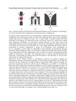
An example of the functional architecture of the STEP-compliant intelligent CNC
(Intelligent STEP-NC) is shown in Fig. 11.24. This is composed of 1) Control mod-
ules covering various intelligent control functions, such as monitoring, decision mak-
ing, execution, and so on, 2) SFP/TPG (shopfloor programming/toolpathgeneration)
11.6 STEP-CNC System 419
modules, which are extended HMIs comprehensively covering part programming
and toolpath generation based on a STEP-NC data model, 3) Common DB mod-
ules providing comprehensive data for the SFP/TPG and control modules, 4) non-
machining modules such as Setup Manager, Inspector, and Learner.
standard
CAD data
interface
machining
feature
recognition
process
planning
setup tools
cutting
param eters
Input
manager
Process
planner
featrure_based
tool-path
generation
direct input
data for NCK
NURBS
tool-path
for NCK
Toolpath
generator
cutting
simulation
interference
check
Simulator
Communicator
automatic
setup
Setup
manager
machining
feature
DB
machining
resource
DB
machining
process
DB
machining
knowledge
DB
toolpath
DB
inspection
DB
negotiation
and bidding
non-linear
process plan
schedule
Decision
maker
emergency
handling
diagnosis
emergency
handler
expert
system
analyze
successful
Learner
NURBS
interpolation
NCK/PLC
next task
selection
adaptive
control
Executor
tool
monitoring
emergency
machining
status
monitor
in-process
inspection
post-process
inspection
Inspector
CAD data
workpiece
SFP/TPG modules CommonDB
modules
Contorl modules
OMM
Non-machining
modules
Machine tool
Machined
workpiece
Other
CNC
holons
Fig. 11.24 A functional architecture of intelligent STEP-CNC
The control modules involve intra-task management of the CNC such as Decision
Maker, Executor, NCK/PLC, Monitor, Emergency Handler, and Inspector.
• Decision Maker: This schedules the task, selecting the next task from various
alternatives from a non-linear process plan. The non-linear process plan includes
alternative process plans, and can be represented by an AND-OR-type graph to
be explained later. One of the critical decisions is to assign the priorities between
the scheduled task and the newly invoked task by the emergency handler and the
inspector.
• Executor: This converts the task into commands and passes them to NCK/PLC.
If the task is a machining operation, it retrieves the corresponding toolpath from
the Tool-Path DB and passes it to NCK/PLC. If the task is a tool change, it finds
the tool in the tool magazine and passes it to NCK/PLC. Executor keeps track of
the commands executed by NCK/PLC for adaptive control.
• NCK/PLC: NCK interprets the toolpath commands and executes them by activat-
ing the servo mechanism, while PLC executes machinery commands, such as tool
change and workpiece loading/unloading. For free-form surface machining, NCK
is capable of NURBS interpolation in which accurate and high-speed machining
can be carried out with reduced data.
• Monitor: The entire machining status is continuously monitored by capturing in-
formation from sensor signals. Tool monitoring and emergency detection are cru-
420 11 STEP-NC System
cial tasks. The results are sent to the emergency handler and/or the decision maker
accordingly.
• Emergency Handler: In case of an emergency, which is monitored and reported
by the monitor, the emergency handler makes a diagnosis and decides what to
do about it. The result is sent to the decision maker for the final decision and
scheduling. For example, in the case of tool breakage, the emergency handler
retracts the tool, and checks if an alternative tool is available in the tool magazine
(through Machine Resource DB). If one is available the operation is resumed with
the alternative tool, otherwise it reports to the decision maker and waits for a final
decision. The emergency handler can be thought of as a subtype of the decision
maker, specializing in dealing with emergency.
• Inspector: In-process and post-process inspections are carried out automatically
by the inspector. In either case, inspection is done on the machine tool by OMM
(on-machine measurement). The inspector generates the toolpath for the touch
probe and stores the data into the Inspection DB. Any geometrical errors between
the designed part and the machined part are found by comparing the data of the
inspection DB with that of the Machining Feature DB.
The SFP/TPG modules incorporate the CAM functions into the shopfloor pro-
gramming system based on the STEP-NC data model. These include Input Manager,
Process Planner, Toolpath Generator, and Simulator.
• Input Manager. The roles of the input manager are CAD data interface han-
dling and machining feature recognition. It translates standard CAD data (STEP,
AP203) into built-in geometric modeling kernel data, recognizes the machin-
ing features, and extracts the feature attributes required for machining. Output
is stored in the Machining Feature DB.
• Process Planner. This determines the processing sequence, operations, fixtures,
setups and cutting tools required to machine the features. The processing se-
quence is represented by a non-linear process plan so that the decision maker can
select an appropriate plan at the time of execution. Optimal cutting parameters,
machining strategies and tools for operations are determined using the Machining
Knowledge DB. For this, a knowledge-based process planning system is required.
Output is stored in the Machining Process DB.
• Tool-Path Generator. This generates toolpaths both for machining and measure-
ment. It can generate a complete path including approach, departure, and connec-
tion path between the machining or measurement paths. The generated toolpaths
are stored in the Tool-Path DB, which is accessed by NCK/PLC. As NCK/PLC is
able to interpret NURBS curves directly, the toolpath generator does not segment
the toolpath of a freeform curve into lines/arcs.
• Simulator. Prior to actual machining, it is necessary to perform a cutting simula-
tion to verify the given toolpath and to detect any possible errors. The simulator
finds undercut or gouging and tool interference by cutting simulation. In addition
to error detection in the toolpath, optimal feedrate is calculated by using the re-
quired material removal rate during the solid cutting simulation. Output is stored
in the Tool-Path DB and the Machining Process DB.
11.6 STEP-CNC System 421
The other functions are as follows:
• Setup Manager. This supports the part setup operation. Once the part is loaded
onto the machine, it finds the datum position by moving a touch probe using the
workpiece and fixture geometry information.
• Learner: Information captured during machining is analyzed by an expert algo-
rithm, and stored in the Machining Knowledge DB.
• Common DB modules: These DB modules are the repositories of data that are
generated, updated, and retrieved by control modules and SFP/TPG modules. Ma-
chining feature DB, machining process DB, toolpath DB, and inspection DB are
short-term databases and machine resource DB and machining knowledge DB
are long-term databases. On completion of the part machining, the short-term
database is cleared.
• Communicator. The communicator is responsible for the interactions with exter-
nal units, such as the CAD/CAM system, shopfloor control system, and human
operator:
1. When requested by the CAD/CAM system, the CNC sends the part program
in the current CNC DB.
2. When requested by the shopfloor control system, it reports the current status
including the progress of machining, and problems that occurred during ma-
chining.
3. When the execution of a certain operation is impossible due to unexpected
problems it sounds an alarm for operator attention.
Assuming that the intelligent STEP-NC presented is developed, an operational
scenario is shown in Fig. 11.25 to illustrate how it works. The part programmer (user)
designs a part to be machined as a workpiece in a CAD system supporting an AP 203
data model. Then, the user goes to a shopfloor programming (SFP) system installed
in either an offline CAM system (external SFP) or a CNC system (built-in SFP).
Then, the input manager recognizes the machining features and stores them in the
machining feature DB. For each machining feature, a process plan is specified in the
process planner module in terms of workingstep including machining operation and
strategy together with cutting tools and cutting conditions specified in the process
planner module. Considering the shape of the machining features, the user provides
an alternative sequence of workingsteps graphically. Then, the CNC generates the
toolpath for the cutter and touch probe (using its toolpath generator), which can be
shown graphically by the simulator. After verification of the toolpath, the operation
is started by pressing the cycle start button. When a tool breakage is detected, it
stops the operation and invokes the emergency handling mechanism, followed by
reporting to the decision maker. After the emergency case has been solved, when the
inspection workingstep is required, the decision maker orders the inspector to invoke
the necessary action.
422 11 STEP-NC System
Machining
feature
DB
Machining
knowledge
DB
Machining
process
DB
CAD data
Feature recognition
Process planning
Process sequence graph
Selection of the next task
None?
END
Resource
available?
Toolpath generation
Cutting simulation
Interface?
NCK Adaptive control
Problem?
Monitoring
Emergency handling
Negotiation / bidding
Possible?
Transmission the task
to other NC holon
Quality OK?
Inspection
DB
OMM
Machining
Resource
DB
Toolpath
DB
Y
Y
Y
Y
N
N
N
N
N
Fig. 11.25 The operation scenario in intelligent STEP-NC
11.7 Worldwide Research and Development
Due to its enormous impact STEP-NC draws keen attention from academic commu-
nities as well as major industries worldwide. They have different perspectives from
each other. This difference is well reflected in the current state of STEP-NC R&D
efforts throughout the world. In this section, we will introduce several representa-
tive researches, even though a large number of passionate endeavors are on-going
worldwide.
11.7.1 WZL-Aachen University (Germany)
Research at WZL has focused on optimizing manufacturing planning by close cou-
pling of a CAM System and CNC Controller. This is depicted in Fig. 11.26 in the
form of a CAM client on the CNC. Since the main requirement is to assure the
usability of existing machine tools and controllers, a post-processor is still neces-
11.7 Worldwide Research and Development 423
sary to translate the process information into the data format of the specificCNC.
However, even with the step of post-processing it is possible to enable interoperable
process planning with seamless bidirectional data flow on a high information level
if the post-processing of the information occurs as close to the specificCNCandas
late as possible before beginning the manufacturing operation. If each CNC has its
own, customized post-processor, then the input information can be controller inde-
pendent. Information that cannot be transferred to and from the controller with the
NC program file, can be transferred via direct software interfaces between the CAM
System and CNC (CAM–CNC Coupling). This brings the high-level information of
the CAM system to the shopfloor level and the CNC. Thus, this allows enriched
information management at the machine tool level as well as feedback of process
information to the CAM system.
all planning information
available until down (in)to
the controller
load NC program
NC start/stop
tool data
coordinate systems
current position
etc.
.
.
.
.
.
.
no program changes
on G-Code level
PDM
no programming
shopfloor
CAD/
CAD/
CAM
CAM
CAM
CAM
TM
TM
CAQ
CAQ
CAM
CAM
Client
Client
PP
PP
CAM
CAM
Client
Client
PP
PP
CAM
CAM
Client
Client
PP
PP
CAM
CAM
Client
Client
PP PP
PP PP
Fig. 11.26 CAM–CNC coupling based on consistent data management
Such a CAM client system might take the form of an integration framework that
allows integrating software solutions of different providers (e.g. toolpath planning
functionalities, 3D simulation of the NC program, acquisition of the real geometry
of the workpiece and its consideration for toolpath planning, provision of geome-
try information for NC integrated collision avoidance systems). A possible detailed
layout of such a system and its seamless PDM integration with all other process
planning software systems in order to enable true interoperable machining based on
common and consistent data is one of the current research topics at WZL.
424 11 STEP-NC System
11.7.2 ISW-University of Stuttgart (Germany)
The Institute for Control Engineering of Machine Tools and Manufacturing Units
(ISW) at the University of Stuttgart researches in the area of the CAD/ CAPP/ CAM/
CNC process chain. The work focuses on methodologies, data models and software
tools to utilize bidirectional information exchange between CNC and a unified man-
ufacturing process planning database capturing STEP-NC information as illustrated
in Fig. 11.27.
During the EU STEP-NC project and together with POSTECH of Korea during
the IMS/EU STEP-NC project, ISW developed a STEP-NC data model for turn-
ing. To verify the turning data model, ISW developed a Computer–Aided Planning
demonstrator for turning, “STEPturn”, and a software module to convert STEP-NC
data into the Siemens ShopTurn CNC data format. For the purpose of optimization of
machining processes, e.g. in a small-batch manufacturing environment, the feature-
based process model of STEP-NC is being utilized to structure process data acquired
in open CNCs and open servo drive controllers. Relating this information about ex-
ecuted machining workingsteps to the corresponding manufacturing features and
machining operations as well as additional context information, like the executing
machine tool, helps to build a comprehensive manufacturing knowledge database.
CAD/CAM systems
STEP-NC server
Machine tool simulation CNC Machining process
STEP-NC
database
STEP-NC
STEP-NC
Drive interface
Drive interface
Fig. 11.27 Infrastructure to acquire process data
11.7 Worldwide Research and Development 425
11.7.3 POSTECH (South Korea)
The National Research Laboratory for STEP-NC Technology (NRL-SNT) at POS-
TECH has made the following achievements related to STEP-NC technology:
• Development of Korea STEP-NC: STEP-CNC system for milling
• Development of TurnSTEP: STEP-CNC system for turning
• Development of the data model for turning (ISO14649 Part 12 and 121) with
ISW-University of Stuttgart
• Suggestion and reflection on revision of the ISO14649 data model for milling
• Promotion of international and domestic seminars for STEP-NC
NRL-SNT developed two types of STEP-CNC system: Korea STEP-NC for
milling [Suh, et al., 2003 [140]] and TurnSTEP for turning [Suh, et al., 2006 [13]].
The following issues have been considered in designing the architecture of STEP-
CNC and are also technical contributions for implementation of STEP-NC.
• Full compliance with ISO14649 and STEP APs
• Suite of STEP-manufacturing
• Distributed architecture for e-manufacturing
• Extension to intelligent/autonomous CNC execution
• Feature recognition/mapping capability
• Tolerance handling capability
• Optimization of the machining sequence for the CNC controller
• Internet interfacing
• XML support
• Accommodation of conventional CNC
• Automated/interactive generation capability
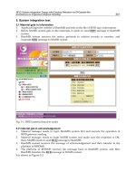
Korea STEP-NC is an integrated system including CAD/CAM/CNC modules
based on the open-modular architecture. It is composed of five modules as shown
in Fig. 11.28: i) PosSFP (Shop Floor Programming), ii) PosTPG (Tool–Path Gen-
eration), iii) PosTPV (Tool–Path Viewer), iv) PosMMI (Man–Machine Interface),
and v) PosCNC. For communication between these modules CORBA is used. Korea
STEP-NC is capable of execution of STEP-NC code without G-code and for direct
interpolation of STEP-NC toolpaths using Soft-NC technology.
TurnSTEP for rotational parts fully supports ISO14649 Part 12 and 121 as a
means for verifying the data model. It is composed of three subsystems: i) CGS
(Code-Generating System), ii) CES (Code-Editing System), and iii) ACS (Au-
tonomous Control System), as illustrated in Fig. 11.29.
The three subsystems interface to the Internet together with a CAD system gener-
ating a part-geometry file, and the STEP-NC repository. CGS is used for generating
neutral (hardware independent) part programs, and CES is for customizing the neu-
tral part program for the machine tools that will be used for executing the STEP-NC
code. Finally, ACS is used for controlling the machine tools based on the hardware
converted STEP-NC code. The developed STEP-NC repository enables data sharing
426 11 STEP-NC System
CORBA
CORBA
PosSFP
PosTPG
PosTPV
CORBA
PosMMI
PosCNC
Machine
AP203 data
Machined part
Fig. 11.28 The prototype Korea STEP-NC and the machined part
STEP/STEP-NC on the Internet
STEP AP(CAD) files ISO 14649 part program
ISO 14649 part program
EPSG
CNC NCK/PLC
• Input: STEP AP (CAD) files
• Output: ISO 14649 part program
• Functions
- Part visualization
- Machining feature recognition
- Generation of hardware-
independent Neutral Process
Sequence Graph (NPSG)
- Generation of ISO 14649 part
program
- Interpretation/Edit of ISO
14649 part program
CGS
(Code -generation System)
• Input: ISO 14649 part program
• Output: HPSG, EPSG
• Functions
- Interpretation of part program
- Verification of logical contents
- Generation of Hardware-
dependent Process Sequence
Graph (HPSG)
- Generation of toolpath
- Generation of Executable
Process Sequence Graph
(EPSG)
CES
(Code-edit System)
• Input: ISO 14649 part program
• Output: Machined part
• Modules
- Setup Manager
- Intelligent Scheduler
- Adaptive TPG
- OMM & Quality Report
- Remachining
- Emergency handling
- Monitoring/Adaptive Control
ACS
(Autonomous Control System)
Fig. 11.29 Three subsystems of TurnSTEP
anytime, anywhere and on any platform. In addition, by expressing STEP data using
XML as a core technology of the repository, product data can be easily stored and
shared across the Web. A translator has been developed to convert STEP data in the
clear text format into XML and vice versa.
11.7.4 Ecole Polytechnic F
´
ed
´
erale of Lausanne (Switzerland)
STEP-NC work at the EPFL concentrated on EDM with other Swiss partners. As
well as control based on STEP-NC, design features, feature-based process planning
11.7 Worldwide Research and Development 427
and optimization methods are being developed. For manufacturing, possible feature
information from CAD may or may not be useful for manufacturing, depending on
the reasons for which they were introduced. Current work is on Malcolm Sabin’s
back-building process planning method, involving recognizing and selecting sets of
features and removing them successively until the desired stock is reached. The fea-
tures removed are recorded for organization into a ‘micro’ process plan for machin-
ing using STEP-NC. This work is also related to another on-going project, on eco-
evaluation, where it is planned to define methods for adaptive control, optimizing
ecological parameters, based on STEP-NC.
11.7.5 University of Bath (UK)
Research at the University of Bath is developing a novel universal manufacturing
platform that utilizes the STEP-NC data models and accentuates it with the function-
ality of mobile agents and manufacturing knowledge-bases. Figure 11.30 illustrates
the conceptual view for the platform where various CAx applications can exchange
information seamlessly. In addition to CAD, CAM, CAPP and CNC interfaces, busi-
ness applications such as ERP, scheduling and costing can also exchange information
with the various systems. This allows the systems to link business information to the
manufacturing data and resources.
In order to achieve full interoperability, the platform requires abstraction of re-
sources, encoding relevant knowledge in a standardized manner and communication
infrastructure to transfer data from one application to another. The STEP-NC data
model is utilized as the basis for the representation of manufacturing knowledge
contained within the platform. An XML-based structure to represent resources has
therefore been developed to support encoding of the various CAx system capabilities.
The open approach used in the developmentof the XML resource schema allows it to
be modified to comply with the new standards currently being developed for resource
representation.
11.7.6 NIST (USA)
Interoperability between discrete parts manufacturing equipment is a large part of
NIST’s standards work conducted by the Manufacturing Engineering Laboratory
(MEL). MEL’s Smart Machining Systems program is focusing on issues relevant
to CNC interoperability. These smart machining systems are envisioned to know and
communicate their capabilities and condition to monitor and optimize their opera-
tions autonomously, to assess the quality of their output and to learn and improve
themselves over time. The program considers “smart data” to be vital to achieving
smart machines.
428 11 STEP-NC System
CAD
System
CAM
System
CNC
CAV
System
CAD
Interface
Costing
Interface
CMM
Interface
Tracing
Interface
CNC
Interface
Other
Interface
Verification
Interface
Communication Hub
Manufacturing Knowledge
Manufacturing Data Warehouse
Fig. 11.30 Universal manufacturing platform architecture
The NIST Advanced Technology Program (ATP) funded a project to validate the
use of STEP-NC in manufacturing applications. This project, the Model-Driven In-
telligent Control of Manufacturing (also known as the “Super Model” project), be-
gan in 1999 with the goal of using STEP-NC and other standards to develop an open
database of all the information necessary to design and manufacture a part. While
NIST understands the value of standards-based data exchange, it is the “smart data”
component that is expected to revolutionize machining. Toward this end, NIST has
developed a dynamic optimizer that uses physics-based models of machining, cou-
pled with measurements of machine tool performance and tool characteristics, to
generate optimal speed and feed settings that reduce cycle times compared with con-
servative handbook values. The Matlab-based optimizer was recently coupled with a
STEP-NC front end that takes a process plan for turning, extracts relevant informa-
tion for optimization, runs the optimizer, and merges the optimized parameters back
into the original STEP-NC file.
11.8 Future Prospects
Research and development on STEP-Manufacturing has been actively pursued and
it has been demonstrated to work in practice both internationally and locally. At
present, an effort has been made to apply the techniques to real industrial areas.
However, truly, it is hard to realize full STEP-Manufacturing in one step due to the
time, cost and technological difficulties. For this reason, the authors suggested the
STEP-Manufacturing Roadmap more focused on the STEP-NC domain, as shown
in Table 11.3. This roadmap is composed of three steps as the specific approach
11.8 Future Prospects 429
methodology for the formalization of the STEP-Manufacturing environment. The
roadmap takes into consideration the following itemized strategies:
• Collaborative participation with many manufacturing-related companies
– Collaborative interaction with design-engineering-machiningcompany chains,
CAD/CAM software users, CNC controller developers, CNC machine tool
users and/or builders
• Inducement toward an information-oriented and international
– Spread to information-oriented company and information exchange among
collaborating companies
– Gradual extension from local cluster to global environment and from metal
working to other industrial sectors
• Consideration of compact and economical research and development
– Practical use from conventional products to new intelligent STEP-based prod-
ucts
– Inducement of implementation from partial to whole
– Technology and service offered through Web services
– Maximum utilization of accumulated know-how from R&D organizations
Despite the short history of STEP-NC and on-going development of this standard,
a large number of research works have been carried out across the whole world. From
the perspective of the STEP-NC data model, milling and turning data models have
been published as International Standards, EDM is in the process of being intro-
duced, and other data models including the machine tool data model, inspection and
rapid prototyping are currently in progress. Simultaneously, the second edition ver-
sions of some ISO 14649 parts have been under development in order to complement
the first versions.
From the perspective of STEP-CNC systems, current research for the first type
of STEP-CNC, which simply incorporates ISO 14649 in a conventional controller
via post processing, have been carried out by the consortia that are composed of
many CAD, CAM, CNC vendors and user groups. With the development of STEP-
NC technology, the second type of STEP-CNC, having an ISO 14649 interpreter,
will replace G-code-based controllers or the first type of STEP-CNC. Finally, the
third type STEP-CNC that enables performance of ‘intelligent’ and ‘autonomous’
machining based on the comprehensive information will dominate the CNC market.
Considering the current momentum of research in STEP-NC areas, these challenges
will come true within a score of years.
430 11 STEP-NC System
Table 11.3 STEP-Manufacturing roadmap
1 step (the beginning period) 2 step (the employment period) 3 step (the completion period)
Objective/
Benefit
STEP-Mfg infra introduction
through the minimum investment
Merit acquisition of STEP-Mfg by
STEP-Mfg settlement
e-Mfg paradigm implementation
based on STEP-Mfg
Time frame 2 year (TBA) 3~4 year (TBA) After 5 year (TBA)
Infra range Intranet (in company) Internet (in local area) Internet (international)
Information
exchange level
Hybrid
(STEP, STEP-NC, G-code)
Partial STEP-Mfg
(STEP AP203, ISO14649)
Full STEP-Mfg
(STEP APs, ISO14649, )
Implementation
level
CNC
CAD/
CAM
Type 1 (conventional control)
via post-processing
Legacy software with
STEP-NC interface
(ST-Plan, ST-Machine)
Type 2 (new control)
via new & w/STEP-NC interpreter
(Siemens)
STEP & STEP-NC interpreter,
STEP-NC converter
(G-code → STEP-NC)
STEP & STEP-NC based
CAPP/CAM
(PosSFP, TurnSTEP-CGS)
Type 3 (intelligent control)
via new & intelligent controller
(TurnSTEP-ACS)
CAPP/CAM for
intelligent STEP-Mfg
(TurnSTEP-CES)
Required technology
STEP-x
interface
Web
service
DB build-up
STEP-NC interpreter,
Post-processor for Type 1
(STEP-NC → G-code)
STEP, STEP-NC interpreter
Web-service build-up in server side
(settlement of web-service range)
STEP-Mfg application build-up
in client side
Client-Server harmonization and
improvement
Local DB
Global DB
(STEP-Mfg repository)
Global DB
(STEP-Mfg repository)
Role division
Company
R&D center
Government
Intranet infra in company,
STEP-Mfg introduction
STEP-Mfg component technology
research and spread
STEP-Mfg introduction support,
local IT infra build-up business
STEP-Mfg infra employment
Component technology development,
Conformance verification
Infra technology employment business,
Local IT infra build-up business
e-Mfg infra employment
Verification of reliability,
conformance, interoperability
Commercial use business,
certification business,
IT infra enlargement (nation)
Appendix A
Turning and Milling G-code System
A.1 Turning
Table A.1 G-codes for turning
G- Grp. Function Format
code
G00 1 Rapid traverse [X /U ][Y /V ][Z /W ]
G01 1 Linear interpolation [X /U ][Y /V ][Z /W ]
G02 1 Circular interpolation [X /U ][Y /V ][Z /W ]
in clockwise direction [R /I J K ]
G03 1 Circular interpolation [X /U ][Y /V ][Z /W ]
in counter-clockwise [R /I K ]
direction
G04 0 Dwell [X /U /P ]
G10 0 Programmable data P [X /U ][Y /V ][Z /W ]
input [R /C ]Q
G17 16 Selecting XY plane
G18 16 Selecting ZX plane
G19 16 Selecting YZ plane
G20 6 Inch (or SI) system
G21 6 Metric system
G22 9 Stored stroke check func- [X /U ][Y /V ][Z /W ]
tion on I J K
G23 9 Stored stroke check func-
tion off
G25 8 Spindle vibration moni-
toring off
G26 8 Spindle vibration moni-
toring on
G27 0 Moving to origin and [X /U ][Y /V ][Z /W ]
check
431
432 A Turning and Milling G-code System
G28 0 Moving to origin [X /U ][Y /V ][Z /W ]
G29 0 Moving from origin [X /U ][Y /V ][Z /W ]
G30 0 Moving to 234 origin P [X /U ][Y /V ][Z /W ]
G31 0 Skip P [X /U ][Y /V ][Z /W ]
G32 1 Thread cutting [X /U ][Y /V ][Z /W ]
G34 1 Variable lead thread [X /U ][Y /V ][Z /W ]K
cutting
G36 0 Tool radius compen- [X /U ][Y /V ][Z /W ]
sation on in X-direction
G37 0 Tool radius compen- [X /U ][Y /V ][Z /W ]
sation on in Z-direction
G40 7 Tool radius compen-
sation off
G41 7 Tool radius compen-
sation on left side
G42 7 Tool radius compen-
sation on right side
G50 0 Setting up work coord- [X /U ][Y /V ][Z /W ]
inate system
G52 0 Setting up local coord- [X /U ][Y /V ][Z /W ]
inate system
G53 0 Setting up machine coord- [X /U ][Y /V ][Z /W ]
inate system
G54 14 Selecting work coordinate [X /U ][Y /V ][Z /W ]
system
G55 14 Selecting work coordinate [X /U ][Y /V ][Z /W ]
system
G56 14 Selecting work coordinate [X /U ][Y /V ][Z /W ]
system
G57 14 Selecting work coordinate [X /U ][Y /V ][Z /W ]
system
G58 14 Selecting work coordinate [X /U ][Y /V ][Z /W ]
system
G59 14 Selecting work coordinate [X /U ][Y /V ][Z /W ]
system
G65 0 Calling macro P L A B C D E F H M
Q R S T U V W X Y Z
I I J J K K
G66 12 Calling macro modal P L A B C D E F H M
Q R S T U V W X Y Z
I I J J K K
G67 12 Macro call off
G68 4 Mirror image on
G69 4 Mirror image off
G70 0 Finish cut cycle on P Q
G71 0 Outer diameter/Internal U R
diameter turning cycle P Q U W
G72 0 Rough facing cycle W R
P Q U W
Table A1 (continued)