Rules of Thumb for Mechanical Engineers 2010 Part 4 pps
Bạn đang xem bản rút gọn của tài liệu. Xem và tải ngay bản đầy đủ của tài liệu tại đây (1.22 MB, 25 trang )
Thermodynamics
65
P
The thed efficiency
of
the
cycle
is:
Eriwn
Cycle
T
Figure
11.
Ericsson
cycle.
This
cycle (Figure
11)
can
also
come very close to at-
taining the
thermal
efficiency
of
a
Carnot cycle. The isother-
mal
processes can
be
attained
by reheating and intercool-
ing.
Its
application is most
apprapriate
to
rotating
machinery.
The
four
processes involved
are:
1-2
Isothermal compression (energy rejection)
2-3
Heat
addition
at
constant pressure
3-4
Isothed expansion (energy input
and
power
out-
4-1
Heat
rejection
at
constant
pressure
put)
The
heat
flow
in
and
out
of
the system
and
the work input
and
work output
terms
are:
The thermal efficiency
of
the cycle is:
T3
-
Tl
rlthermal=-
T3
Todd
R
.
Monroe. P.E.,
Houston.
Texas
Perry
C
.
Monroe. P.E.,
Monroe Technical Services. Houston. Texas
Basic Mechanical Seal Components
67
Equipment Considerations
80
Sealing Points
67
Mechanical Seal Classifications
68
Basic Seal Designs
68
Basic Seal Arrangements
72
Basic Design Principles
74
Materials of Construction
77
Desirable Design Features
79
Calculating Seal Chamber Pressure
81
Seal Flush Plans
82
Integral Pumping Features
85
Seal System Heat Balance
87
Flow Rate Calculation
89
References
91
Mechanical Seals
67
BASIC MECHANICAL SEAL COMPONENTS
All mechanical seals are constructed with three basic
groups of parts. The first and most important group is the
mechanical seal faces, shown in Figure
1.
The rotating
seal face is attached to the shaft, while the stationary seal
face is held fixed to the equipment case via the gland ring.
The next group of seal components is the secondary
sealing members. In Figure
1,
these members consist of a
wedge ring located under the rotating face, an O-ring located
on the stationary face, and the gland ring gasket.
The third group of components is the seal hardware, in-
cluding the spring retainer, springs, and gland ring. The pur-
pose of the spring retainer is to mechanically drive the ro-
tating seal face, as well as house the springs. The springs
are a vital component for assuring that the seal faces remain
in contact during any axial movement from normal seal face
wear, or face misalignment.
Figure
1.
Mechanical seal components.
(Courtesy
of
John
Crane,
Inc.)
SEALING POINTS
There are four main sealing points in a mechanical seal
(see Figure
2).
The primary sealing point is at the seal
faces, Point A. This sealing point is achieved by utilizing
two very flat, lapped surfaces, perpendicular to the shaft,
that create a very treacherous leakage path. Leakage is
further minimized by the rubbing contact between the
ro-
tating and stationary faces. In most cases, these two faces
are made of one hard material, like tungsten carbide, and
a relatively soft material such as carbon-graphite. The car-
bon seal face generally has the smaller contact area, and is
the wearing face. The
O.D.
and I.D. of the wearing face rep-
resent the “seal face dimensions,” and
are
also generical-
ly referred to as the “seal face” throughout this chapter.
The second leakage path, Point
B,
is along the shaft
under the rotating seal face. This path is blocked by the sec-
ondary O-ring. An additional secondary O-ring, Point
C,
is
used to prevent leakage between the gland ring and the sta-
tionary seal face. Point D is the gland ring gasket which pre-
vents leakage between the equipment case and the gland.
Figure
2.
Sealing points.
(Courtesy
of
Durametallic
Corp.)
68
Rules of Thumb
for
Mechanical Engineers
Single
MECHANICAL SEAL CLASSIFICATIONS
Multiple
Mechanical seals can be categorized by certain design
characteristics or by the arrangement in which they’re
used. Figure
3
outlines these classifications. None of these
designs, or arrangements,
are
inherently better than the
other. Each has a specific use, and a
good
understanding of
the differences will allow the user to properly apply and
maintain each seal type.
Inside
Outside
Double Face
to
Face
Tandem
Staged
By
Design
I
I
I
I
I
I
yGikql~*qflPvrherTypa/
Ei]Ei
Balanced Multiple Spring Non-Pusher
Type
I
Figure
3.
Mechanical seal classifications.
(Courtesy
of
Durameta//ic Corp.)
BASIC SEAL DESIGNS
Pusher Seals
The characteristic design of a pusher seal is the dynam-
ic O-ring at the rotating seal face (see Figure
4).
This O-ring
must move axially along the shaft or sleeve to compensate
for any shaft or seal face misalignment as well as normal
face wear. The advantages of a pusher seal are that the de-
sign can
be
used for very high-pressure applications (as
much as
3,000
psig), the metal components are robust and
Figure
4.
Basic pusher seal.
(Courtesy of Duramefallic
cOrp-)
Mechanical Seals
69
come in special alloy materials, and the design is well
suited for special applications.
The disadvantages of the pusher design are related to the
dynamic O-ring. In a corrosive service, the constant relative
motion between the dynamic O-ring and shaft wears away
at the protective oxide layer of the shaft or sleeve materi-
al, causing fretting corrosion. The fretting will wear a
groove in the shaft or sleeve, providing a leakage path for
the sealed fluid.
An additional limitation
of
the dynamic O-ring is the prob-
lem of “hang-up,” shown in Figure
5.
In applications where
the sealed fluid can “salt-out” or oxidize, like caustic
or
hy-
drocarbons, the normal seal weepage can build under the
seal faces and prevent forward movement, thereby creat-
ing a leakage path.
Figure
5.
Dynamic O-ring “hang-up.” (Courtesy
of
Du-
rarnetallic Corp.)
Another characteristic of the pusher seal design is the use
of coil springs for providing mechanical closing force.
These springs can be either a single coil spring (Figure
6)
or a multiple arrangement of springs (Figure
7).
Mechan-
ical seals using a single coil spring are widely used because
of their simple design, and the large spring cross-section is
good for corrosion resistance. The disadvantages
of the sin-
gle coil are that
the
applied spring force is very nonuniform
Figure
6.
Single coil spring.
and can cause waviness and distortion to the seal face in
larger sizes. In addition, the spring can distort at high
sur-
face speeds.
Multispring seals (Figure
7)
use a series of small coil
springs spaced circumferentially around the seal face. This
spacing provides a uniform face loading, minimizing the
waviness and distortion attributed to spring forces. The mul-
tispring arrangement is also less susceptible to high-speed
spring distortion under
4,500
fpm.
I
Figure
7.
Multi-spring seal. (Courtesy
of
John
Crane, lnc.)
Nan-Pusher
Seals
The characteristic design feature of the non-pusher, or bel-
lows, seal is the lack of a dynamic O-ring. As shown in Fig-
ure
8,
the non-pusher seal design has a static O-ring in the
drive collar of the rotating seal face unit. This is made pos-
sible by the bellows, which acts as a pressure containing de-
vice,
as
well
as
the spring force component.
This
unique fea-
ture provides advantages over the pusher seal in that the static
Figure
8.
Welded metal-bellows, non-pusher seal. (Cour-
tesy
of
fhrarnetallk COP-)
70
Rules of Thumb for Mechanical Engineers
Figure
9.
Static O-ring, no hang-ups.
(Courtesy
of
Du-
rametallic Corp.)
O-ring virtually eliminates the problem of fretting corrosion
and seal face hang-up, as shown in Figure
9.
There are two basic bellows seal designs available: the
metal bellows and the elastomeric bellows. Figure
8
depicts
a welded metal bellows design, constructed from a series
of thin metal leaflets that are laser welded together at the
top and bottom to form a pressure-containing spring. The
elastomeric bellows (Figure
10)
consists
of
a large rubber
bellows, or boot, that is energized by a single coil spring.
While the non-pusher seal has several advantages over
the pusher seal, the bellows also provides this seal design
with its limitations. In the case of the welded metal bellows,
the thin cross-section of the leaflets,
.005”
to
.009”,
limits
Figure
10.
Elastomeric bellows seal.
the pressure at which the design should be applied to
250
psig. This limitation is due to the pressure acting on the
un-
supported seal face, causing severe face deflections. The thin
leaflets also limit the corrosion allowance to
.002”
for
chemical services. The elastomeric bellows design is not
as pressure limited, but does possess the same limitations
as a single coil spring design, in addition to limited chem-
ical resistance of the elastomeric bellows.
Unbalanced
Seals
For all mechanical seals, the pressure of the sealed fluid
exerts a hydraulic force on the seal face. The axial com-
ponent of
this
hydraulic force is known as the hydraulic clos-
ing force. Unbalanced seal designs have no provisions for
reducing the amount of closing force exerted on the seal face,
and for pusher seals, the characteristic trait of this design
is for the seal faces to be above the balance diameter, as
shown in Figure
11.
The balance diameter can be determined
by locating the innermost point at which pressure can act
on the seal faces. For almost all pusher seal designs, that
point is the I.D. of the dynamic O-ring.
A
more detailed discussion of seal balancing can be
found in the Basic Design Principles section of this chap-
ter. The point to be made here is that the unbalanced seal
design is the preferred design for low-pressure applica-
tions. Seal face weepage is directly related to the closing
force acting on the seal face; the higher the closing force,
‘Opening Force
Atmospheric Pressure
I
Closlng Force‘
Balance Diameter
Figure
1 1.
Unbalanced seal.
(Courtesy
of
Durarnetallic
Corp.)
the lower the seal face weepage. Unbalanced seal designs
inherently have higher closing forces and therefore less seal
weepage at lower pressures. Additionally, unbalanced seals
are more stable during off-design equipment conditions such
Mechanical
Seals 71
Seal
ID
m)
112
to
2
over
2
as cavitation, high vibration, or misalignment. The only dis-
advantage to the unbalanced seal design is the pressure lim-
itations. The closing force exerted at the seal face can
reach a point where it overcomes the stiffness of the lu-
bricating fluid and literally squeezes the fluid from be-
tween the seal faces. This is a destructive condition that
should be avoided. Figure
12
lists some recommended
pressure limits for unbalanced seals, based on seal size
and speed
[3].
Shaft
Speed
Sealing
Pressure
(rpm)
@sk)
Up
to
1800
I75
1801
to
3600
100
Up
to
1800
1801
to
3600
50
~~
Balanced Seals
It is apparent from our discussion of unbalanced seal de-
signs that the primary purpose of a balanced seal is to re-
duce the hydraulic closing force acting on the seal face, and
therefore provide a seal design suitable for high-pressure
applications. For pusher seals, the primary trait of a bal-
anced seal design is the seal faces dropping below the bal-
ance diameter, as shown in Figure
13.
The shaft or sleeve
now has a stepped diameter which allows the seal face di-
mensions to be reduced. This reduction now exposes more
of the front side of the rotating seal face to the seal cham-
ber pressure. Because pressure acts in all directions, this
increased exposure opposes or negates a larger portion of
the pressure and effectively reduces the closing force act-
ing on the seal face. This reduction of the closing force al-
lows for the maintenance of a good lubrication film be-
tween the seal faces at pressures as high as
1,500
psig for
a single pusher seal.
While the use of a balanced pusher seal requires a phys-
ical step in the shaft or sleeve, a non-pusher or bellows seal
design is inherently balanced and therefore requires no
stepped sleeve. This can be an important advantage for
medium-pressure applications.
Figure
13.
Balanced seal. (Courtesy
of
Durametallic
Corp.)
Flexible
Rotor
Seals
Flexible rotor seal designs (Figure
14)
make up the vast
majority of the mechanical seals in service. Some of the ad-
vantages of the flex rotor design are less cost, less axial space
required, and that the springs or bellows are “self-cleaning”
due to the effects of centrifugal force. The disadvantages
are a speed limitation of
4,500
fpm and the inability to han-
dle severe seal face misalignment. Because the gland ring
is bolted directly to the equipment case, the stationary seal
face is prone to misalignment due to pipe strain or thermal
expansion of the equipment case. For each revolution of the
shaft, the flexible rotor must axially compensate for the out-
of-perpendicularity of the stationary seal face.
As
dis-
cussed earlier with fretting corrosion, this can be very
detrimental to reliable seal performance.
I
7
L
~
Figure
14.
Flexible
rotor.
(Courtesy
of
John Crane, lnc.)
72
Rules
of
Thumb for Mechanical Engineers
~
Flexible Stator Seals
Flexible stator seal designs (Figure
15)
make up a small-
er, but very necessary, part of the mechanical seals in ser-
vice. It stands to reason that the disadvantages of the flex-
ible rotor design would be addressed with this design. The
primary advantage of the flexible stator design is its abil-
ity to handle severe seal face misalignment caused by
equipment case distortion by making a one-time adjustment
to the rotating seal face. This is of great importance for large,
hot equipment in the refining and power markets. The
flexible stator is also the design of choice for operating
speeds above
4,500
fpm.
The disadvantages of the flexible stator are higher cost,
increased axial space requirements, and the limitation of
being applied in services with less than
5%
solids.
Figure
15.
Flexible stator.
(Courtesy
of John
Crane,
lnc.)
BASIC SEAL ARRANGEMENTS
Single Inside Seals
The single inside seal (Figure
16)
is by far the most
common seal arrangement used and, for single seals, is the
arrangement of choice. The most important consideration
for this arrangement is that the seal faces are lubricated by
the sealed fluid, and therefore the sealed fluid must be
compatible with the environment. Toxic or hazardous
flu-
ids should not be handled with a single seal. From an emis-
sions standpoint, volatile organic compounds
(VOCs)
have
been effectively contained with emissions of
500
ppm
using a single seal
[6].
For corrosive services, the seal
must operate in the fluid,
so
material considerations must
be reviewed.
Figure
16.
Single inside seal.
(Courtesy
of
Durametal-
lic
Cop.)
Mechanical
Seals
73
While
single outside
seals
(Figure 17)
are
not the arrange-
ment of choice, certain situations dictate their usage. Equip-
ment with a very limited seal chamber area is a good can-
didate for an outside seal. Economics will also impact
the
use of a single outside seal. To prevent the need for very
expensive metallurgies in highly corrosive applications, out-
side seals are sometimes employed. Because all the metal
parts
are
on the atmospheric side of the seal, only the seal
faces and secondary sealing members
are
exposed to the cor-
rosive product.
If
outside seals must be used, always use a
balanced seal design.
Figure
17.
Single outside seal. (Courtesy
of
Durameta//ic
Corp.)
Double
Seals
Double seals
are
used when the product being sealed is
incompatible with a single-seal design.
As
discussed ear-
lier, toxic or hazardous chemicals require special consid-
erations and must be handled with a multiple-seal arrange-
ment. Highly corrosive products can also be safely contained
with a double-seal arrangement. The primary purpose of the
double seal is to isolate the sealed fluid from the atmosphere,
and create an environment in which a mechanical seal can
survive. This is accomplished by using two seals that op-
erate in a different fluid, called a barrier fluid. The barrier
fluid
is
there to provide clean, noncorrosive lubrication to
the seal faces. To assure that the seals are being lubricat-
ed
by the barrier fluid, the pressure
of
the barrier fluid is
maintained at 15-25 psig higher than the product in the seal
chamber area.
This
weepage requires that the barrier fluid
be chemically compatible with the product.
There
are
two
different arrangements for
a
double
seal,
the
buck-to-buck
arrangement (Figure 18) and the
face-to-face
arrangement (Figure 19). The advantage of the back-to-back
arrangement is that none of the metal
seal parts are exposed
to the product.
This
is an ideal arrangement for highly cor-
rosive chemicals. The major disadvantage to
this
arrangement
is that it will not take pressure reversals. Under upset condi-
tions, should the barrier
pressure
be
lost, the inboard
seal
(left
seal
on Figure 18) would
be
pushed open, exposing the seal,
and possibly the environment, to the product.
Face-to-face double-seal arrangements
are
designed to
accommodate pressure reversals. Should the barrier pres-
sure
be
lost, the only effect to the seal would
be
that the sed
faces
are
lubricated by the product instead of the barrier
Figure
18.
Double seal-back-to-back. (Courtesy
of
John Crane,
hc.)
Figure
19.
Face-to-face dual seal. (Courtesy
of
Du-
rametallic
Corp.)
fluid. While this condition could only be tolerated by the
seal for a short time, the potentially major failure of the
back-to-back arrangement has been avoided. The disad-
vantage of the face-to-face arrangement is that one
of
the
seals must operate in the product. This virtually eliminates
its use in highly corrosive products.
74
Rules
of
Thumb
for
Mechanical Engineers
~~~
Tandem Seals
Tandem seals are used when a single seal design is com-
patible with the product, but emissions to the environment
must be severely limited, such as with VOCs. The classi-
cal arrangement of a tandem seal is two seals in series, as
shown in Figure
20.
The primary seal (on the left) functions
just like a single seal in that it contains all the pressure and
is lubricated by the product. The secondary seal (on the
right) serves as a backup seal to the primary and is lubri-
cated by a nonpressurized barrier fluid. The secondary
seal also serves as a second “defense” for containing emis-
sions. Under normal conditions, weepage from the prima-
ry seal is contained in the nonpressurized barrier fluid and
typically vented off to a flare system. In the event that the
primary seal should fail, the secondary seal is in place to
contain the pressure, and the product, until a controlled shut-
down of the equipment can be arranged.
Face-to-face tandem seal arrangements are also avail-
able, and are identical to Figure
19.
The only difference be-
tween the double and tandem seal in this case, with the ex-
ception of their purpose, is that the double seal has a
pressurized barrier fluid and the tandem seal has a nonpres-
surized barrier fluid.
Figure
20.
Tandem seal. (Courtesy
of
John
Crane, Inc.)
BASIC
DESIGN
PRINCIPLES
Seal Balance Ratio
As
a means of quantifying the amount, or percent, of bal-
ance for a mechanical seal, a ratio can be made between the
seal face area above the balance diameter versus the total
seal face area. This ratio can also be expressed as the area
of the seal face exposed to hydraulic closing force versus
the total seal face area. In either case, referring to Figure
2
1,
the mathematical expression for the balance ratio of an
inside seal design is:
OD2
-
BD2
OD2
-
ID2
Balance Ratio
=
where: OD
=
seal face outside diameter
ID
=
seal face inside diameter
BD
=
balance diameter of the seal
As
a general rule of thumb, balanced seal designs use a
balance ratio of
0.75
for water and nonflashing hydrocar-
Figure
21.
Balance ratio for inside seal. (API-682. Cour-
tesy
of
American Petroleum Institute.)
bons. For flashing hydrocarbons, which are fluids with a
vapor pressure greater than atmospheric pressure at the
service temperature, the balance ratio is typically
0.80
to
0.85.
Unbalanced seal designs typically have a ratio
of
1.25
to
1.35.
Mechanical Seals
75
Seal
Hydraulics
As
previously discussed, all mechanical seals are af-
fected by hydraulic forces due to the pressure in the seal
chamber. Both mechanical and hydraulic forces act on the
seal face, and
are
shown in Figure
22.
The total net forces
acting on
the
seal face can be expressed as:
FTotal
=
Fc
-
-I-
Fsp
where:
F,
=
closing force
F,
=
opening force
F,,
=
mechanical spring force
The hydraulic closing force can be described mathemati-
cally as:
7t
F,
=-(oD~
-BD~)(D,)
4
where:
OD
=
seal face outside diameter (in.)
BD
=
balance diameter (in.)
D,
=
AP
across seal face (psi)
Figure
22.
Mechanical seal force diagram.
(Courtesy
of
Durametallic Corp.)
The mechanical closing force, or spring force,
is
ex-
pressed as
Fsp.
The amount of spring force is a function of
the wire diameter, the number of springs, and the length of
displacement. For mechanical seal designs, the range can
be from
5
to
15
lbs of force per inch of
OD
circumference.
As
a general rule, values of
5
to
7
lbs
are
typically used.
The hydraulic opening force can be expressed as:
n:
F,
=
-
(OD2
-
ID2)
(D,)
(K)
4
where:
OD
=
seal face outside diameter (in.)
ID
=
seal face inside diameter (in.)
D,
=
AP
across seal face (psi)
K
=
pressure drop factor
The pressure drop factor
K
shown in the opening force
equation can be viewed as a percentage factor for quanti-
fying the amount of differential pressure that is converted
to opening force as the fluid migrates across the seal face.
Seal faces act as pressure-reducing devices, and their shape
has great impact on the
K
factor. Figure
23
shows various
examples of
K
values and how they affect pressure drop
[9].
A
value of
K
=
1
(100%)
is known as a
converging seal face,
where all of the differential pressure is used for opening
force and the seal relies totally on spring force to remain
closed. For a
diverging seal face,
K
=
0
(O%),
none of the
differential pressure is used for opening force. For normal
flat seal faces, where
K
=
0.5
(50%),
half the differential
pressure is used for opening force. This can also be ex-
pressed as a linear pressure drop across the seal face, and
is commonly used for hydraulic calculations.
Fluid types also affect the pressure drop factor. For light
hydrocarbons, the liquid generally flashes to a gas as
it
mi-
grates across the seal face.
As
the liquid expands, it creates
higher opening forces, and is expressed as
K
=
0.5
to
0.8.
As
a general rule,
K
=
0.5
is used for nonflashing liquids.
and
K
=
0.75
is used for flashing liquids.
I
I
K=
1
convergent
seal faces
K=1
K
=
0.5
flat seal
faces
n=u
\
\\I
K=O
\
.~
divergent seal
faces
ri
Figure
23.
Pressure drop factor
K.
76
Rules
of
Thumb
for
Mechanical
Engineers
Seal face pressure,
or
unit loading, is the most common
term used when discussing the effects of chamber pressure
on the seal faces. The total seal face pressure can be deter-
mined by dividing the Ftoesl equation by the seal face area:
Fc
Fo
FSP
PTod
=
+-
AAA
7t
where:
A
=
-
(OD’
-
ID’)
4
where: Dp
=
AP
across seal face (psi)
B
=
seal balance ratio
K
=
pressure drop factor
Psp
=
spring pressure (psi)
Basic Seal lubrication
Basic seal lubrication occurs as the seal chamber pres-
sure
drives the fluid across the seal faces, forcing it through
the asperities in the seal face caused by surface rough-
ness, porosity, or waviness. Depending on the seal design
and the type of lubricating fluid, one of three basic lubri-
cation modes can
be
used (see Figure
24).
The most common mode of lubrication is
boundary
Zu-
brication.
In
this
case, the lubricant remains
as
a fluid
all
the
way
across
the face, but
is
not visible
on
the
low-pressure side.
This
mode is common when
sealrng
oils,
acids, and
other
non-
flashing liquids in low-
to
medium-pressure applications.
The next lubrication mode is called
phase
tredrz,
and is characteristic of flashing liquids and
high-pressure
ap
plications.
As
the fluid migrates across
the
face,
heat
gen-
erated from fluid shear or rubbing contact elevates
the
fluid
temperature above the vapor pressure, causing a phase
change
from liquid
to
vapor.
As
discussed in the section on
pressure
drop factors, this vaporization can greatly increase
opening
forces and must
be
considered
in
the design
process.
The
third
mode
of
lubrication isfull$uidfilm, and
is
char-
acterized by visible leakage on the low pressure side
of
the
seal face.
This
lubrication mode is used primarily in high
performance, noncontacting
seals,
where
seal
face wear is
virtually eliminated.
Figure
24.
Lubrication
modes.
(Couffesy
of
Durametalic
Corn.)
Mechanical Seals
77
MATERIALS
OF
CONSTRUCTION
Hardware material can be
made
from almost
all
available
metals. These metals are governed by ASTM standards, and
will
not
be
discussed in this section.
Seal Face Materials
The old saying goes that the perfect seal face material
would have the hardness of a diamond, the strength of
alloy steel, the heat transfer abilities of a super conductor,
and the self-lubricating properties of teflon. While a com-
promise to this "standard" is certainly necessary, there are
a few
seal
face materials that come close to these
ideal
prop-
erties. The three best materials available are also the most
common face
materials
used
in the petrochemical industry:
tungsten carbide, silicon carbide, and carbon-graphite.
Tungsten Carbide
Tungsten carbide is a very popular seal face material due
to its good wear characteristic, good corrosion resistance,
and
durability. The material has a very high modulus of
elas-
ticity and is well suited for high-pressure applications
where face distortion is a problem. Tungsten carbide typ-
ically comes in two grades: nickel bound or cobalt bound.
The user must be aware that all tungsten carbides are not
created equal. Mechanical seal grade tungsten carbide
should have very fine grains, with a maximum of
6%-8%
binder material. Depending on the function, some com-
mercial grade tungsten carbides can have as much as
50%
binder material.
For
mechanical seal applications, tungsten carbide coat-
ings should also be avoided because of problems with
coating cracks. The best material configuration for tung-
sten carbide is a solid homogeneous ring.
Silicon Carbide
Silicon carbide has many of the same good qualities as
tungsten carbide, but also contains superior hardness, ther-
mal
conductivity, and
a
very low friction coefficient.
If
not
for the brittle nature of silicon carbide, it would indeed
be
the ideal seal face material. This material typically comes
in
two
grades: reaction bonded and alpha sintered.
The
primary
characteristic
of
reaction-bonded silicon car-
bide is the 8%-12% free silicon found in the structure.
Under conditions
of
seal face contact, this free silicon can
vaporize, leaving behind free carbon atoms
at
the interface.
This reduces the frictional heat at the faces, and promotes
good wear characteristic. The disadvantage to reaction-
bonded silicon carbide is also the free silicon, which reduces
chemical resistance. Chemicals like caustic
or
hydrofluo-
ric acid
will
leach out the free silicon and severely limit good
seal performance.
Alpha sintered silicon carbide, on the other hand, has no
free silicon in the material structure. This provides a seal
face material that is virtually inert to any chemicals, but does
not offer the superior wear characteristics found in reaction-
bonded materials.
Carbon-Graphite
Carbon-graphite is by far the most commonly used seal
face material, and is used almost exclusively as the wear-
ing face of a mechanical seal. Carbon-graphite offers out-
standing antifiction pperties as well as exceptional chem-
ical resistance. This material does have a low modulus of
elasticity and is therefore susceptible to distortion in high-
pressure applications. There are many hundreds of differ-
ent carbon grades available, and like tungsten carbide,
they are not
all
created
equal.
Reputable mechanical seal
manufacturers expend great effort in evaluating and test-
ing suitable mechanical
seal
carbon grades.
To
assure good
reliable seal performance, stick
to
the grades offered by the
seal manufacturers.
78
Rules
of
Thumb for Mechanical Engineers
Tung-Car
Bronze
Ceramic
Carbon
Seal Face Compatibility
Solid tungsten Carbide Ring 750
400
Solid Leaded Bronze Ring 350 177
Solid Pure Ceramic Ring 350 177
Solid Carbon-Graphic Ring 525
27
5
There are a few general items to keep in mind when ap-
plying various seal face combinations:
Spiral Wound
Sythetic
Organic
Fiber With
Nitrile
One of the seal face materials should be harder than the
other, like tungsten carbide versus carbon-graphite.
Gasket
-450
+1200
Gasket
-175
+700
Codes:
A
-
Acids diluted and concentrated
B
-
Water and water solution
C
-
Caustics diluted and concentrated
D
-
Oil
and lubricants
E
-
DryXUlU~ing
X
-
Not recommended
Figure
25.
Seal face compatibility. (Courtesy
of
Du-
rarnetallic Corp.)
For abrasive services, both seal face materials should
be harder than the abrasive particles, such as tungsten
carbide versus silicon carbide.
For fluids with a viscosity less than
0.4
cp, one
of
the
seal face materials should be carbon-graphite.
Additionally, not all seal face materials work well
to-
gether. Figure
25
outlines various seal face combinations
for different types
of
fluids
[4].
Figure
26
shows typical tem-
perature limitations for common seal face materials
1
1.
I
350
I
177
I
Welded Stellite Face on
I
Metal Rina
I
Stellite Face
Silicon-Carbide
I
Solid Silicon Cerbide Ring
I
800
427
Figure
26.
Temperature limitations of seal face materi-
als. (Courtesy
of
Durarnetallic Corp.)
Secondary Sealing Materials
__
Secondary \ealing rnembcr-4 must be made from niatc-
rials that are capable of scaling between two different wr-
faces. Ideallv. resilient materials such
as
elastomeric
o-
.I,
rings should be used whenever temperature and chemical
conditions will allow. For more severe conditions, such as
high-temperature or corrosive environments, specialized ma-
terials like pure graphite or teflon must be used. These
materials offer no resilience and must be formed into dif-
ferent shapes, such as wedges or squares, and be mechan-
ically energized. Figure 27 shows temperature limits for the
most common secondary sealing materials
[
11.
Mechanical
Seals
79
DESIRABLE
DESIGN
FEATURES
Much has been said about the sealing members of a me-
chanical seal. There
are
also many design features that
should be considered for the mechanical
seal
hardware.
~
~
Gland
Rinm
The following is a list of design features that should be
considered for mechanical seal gland rings:
Gland rings should be designed to withstand maxi-
mum seal chamber design pressure, and should be suf-
ficiently rigid
to
avoid any distortion that would impair
reliable seal performance.
A
minimum pilot length of
0.125”
should be used to
properly align the seal to the stationary housing. This
consideration would not apply for cartridge
seal
designs
using centering tabs.
The
seal flush should enter through the gland ring and
be located directly over the
seal
faces. The minimum
pipe tap diameter should be
gff
NPT.
Confined gland ring gaskets should be used when
space and design limitations permit. Examples would
be O-rings or spiral wound gaskets.
Gland rings should be bolted to the seal chamber with
a minimum of four bolts.
Throttle bushings should be
of
a nonsparking and non-
galling material, with a minimum of
0.025”
diametri-
cal clearance.
The stationary seal face should be mounted in the
gland ring with
a
circumferential O-ring or other flex-
ible sealing element. Clamp-type arrangements should
be avoided.
Sleeves
Metal sleeves
are
used with mechanical
seals
to
both
p
tect the equipment shaft, in the case of hook type sleeves,
and provide a means of installing a seal
as
a
complete unit,
as
with the cartridge sleeve design. The cartridge seal is the
design of choice unless space or other design limitations
exist. The following
are
desirable
features
for sleeve
designs:
Shaft
sleeves should have a minimum wall thickness of
Materials of construction should be stainless steel as a
All shaft sleeves should be “relieved” on the
LD.
for
0.
loo“.
minimum.
ease
of
installation.
Shaft sleeves should be manufactured to tolerances
suitable for a maximum sleeve run-out
of
0.002”
TIR
when mounted
on
the shaft.
Shaft sleeve sealing members (O-rings, gaskets, etc.)
should be located as close to the equipment internals as
possible.
Cartridge sleeve designs should
be
mechanically
secured
to the shaft and be capable of maintaining position at
maximum discharge pressure. The sleeve should be
pos-
itively driven with
the
use of drive keys or dog-point
set screws.
80
Rules
of
Thumb
for
Mechanical Engineers
Equipment Checks
One of the most important considerations for reliable seal
performance
is
the operating condition of the equipment.
Many times, mechanical seal failures are a direct result of
poor equipment maintenance. High vibration, misalign-
ment, pipe strain, and many other detrimental conditions
cause poor mechanical seal life. There are also several di-
mensional checks that are often overlooked.
Because half of the seal is rotating with the
shaft,
and the
other half is fixed to a stationary housing, the dimension-
al relationships of concentricity and “squareness”
are
very
important. The centrifugal pump
is
by far the most common
piece of rotating equipment utilizing a mechanical seal.
For
this reason, the dimensional checks
will
be referenced
to
the shaft and seal chamber for a centrifugal pump.
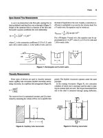
Axial Shaft Movement
Axial shaft movement (Figure
28)
can be measured by
placing a dial indicator at the end
of
the shaft and gently tap-
ping
or
pulling the shaft back and forth. The indicator
movement should be no more
than
0.010’’
TIR
[
11.
Radial
Bearing
U
Figure
28.
Checking pump
for
axial shaft movement.
(Courtesy
of
Durametallic Cop.)
~~
Radial Shaft Movement
There are two types of radial shaft movement (Figure
Mid
Bearing
29)
that need to be inspected. The first type is called
shafi
defection,
and is a good indication of bearing con-
ditions and bearing housing fits. To measure, install the
dial
indicators as shown, and lift up
or
push down
on
the
end
of
the shaft. The indicator movement should not
ex-
ceed
0.002”
TIR
[
11.
The second type of radial shaft movement
is
called
shu#
mn-out,
and
is
a good way to check for a bent shaft con-
dition.
To
measure, install the dial indicators as shown in
Figure
29.
Checking pump
for
radial shaft movement.
(Coudesy
of
Durametallic Cop.)
Mechanical
Seals
81
Seal Chamber Face Run-Out
Figure
29,
and slowly
turn
the shaft. The indicator move-
ment should not exceed
0.003”
TIR
[
11.
As stated
earlier,
because the stationary portion of the me-
chanical
seal
bolts directly to the pump case, it is very im-
portant that the face of the seal chamber be perpendicular
to the
shaft
center-line. To check for “out-of-squareness,”
mount the dial indicator directly to the shaft, as shown in
Figure
30.
Sweep the indicator around the face of the seal
housing by slowly turning the shaft. The indicator move-
ment should not exceed
0.005”
TIR
[
11.
Radial
Bearing
Eearlng-r
Figure
30.
Checking pump
for
seal chamber face
out.
(CouWy of Durametallic Corp.)
run-
Seal Chamber Bore Concentricity
There
are
several stationary seal components that have
close diametrical clearances to the shaft, such as the throt-
tle bushing. For
this
reason, it is important for the seal
chamber to be concentric with the pump shaft. Addition-
ally, for gland ring designs with
O.D.
pilots, the outer reg-
ister must also
be
concentric.
To
measure, install the dial
indicators as shown in Figure
3
1. The indicator movement
should not exceed
0.005”
TIR
[
11.
Figure
31.
Checking pump
for
seal chamber bore con-
centricity.
(Courtesy
of
Durametallic Corp.)
CALCULATING SEAL CHAMBER PRESSURE
The
seal
chamber pressure is a very important
data
point
for selecting both the proper seal design and
seal
flush
scheme. Udortumtely, the
seal
chamber
pressure
varies con-
siderably with different pump designs and impeller styles.
Some pumps operate with chamber pressures close
to
suc-
tion pressure, while others are near discharge pressure.
The easiest and most accurate way to determine the seal
chamber pressure
on
an existing pump
is
simply to mea-
sure
it. Install a pressure gauge into a tapped hole in the seal
chamber, and record the results with the pump running. The
second most accurate method for determining seal cham-
ber
pressure
is to consult the pump manufacturer. If neither
of these two methods is feasible, there are ways of esti-
mating the seal chamber pressure on standard pumps.
82
Rules
of
Thumb
for
Mechanical Engineers
Single-Stage
Pumps
The majority of overhung process pumps use wear rings
and balance holes in the impeller to help reduce the pres-
sure in the seal chamber. The estimated chamber pressure
for this arrangement can be calculated with the following
equation:
where: Pb
=
seal chamber pressure (psi)
P,
=
pump suction pressure (psi)
Pd
=
pump discharge pressure
In
some special cases, where the suction pressure is very
high, pump designers will remove the back wear ring and
balance holes in an effort to reduce the loading on the
thrust bearing. In this case, the seal chamber pressure
(Pb)
will be equal to discharge pressure (Pd).
Another common technique
for
reducing seal chamber
pressure is
to
incorporate pumpout vanes
in
the back of the
impeller. This is used primarily with ANSI-style pumps, and
can be estimated with the equation:
The
final
type of single-stage pump is the double suction
pump, and for this pump design, the seal chamber pressure
(Pb) is typically equal to the pump suction pressure (Ps).
~~~~~ ~ ~
Multistage
Pumps
Horizontal multistage pumps typically are “between
bearing” designs, and have two seal chambers. On the
low-pressure end
of
the pump, the seal chamber pressure
(Pb) is usually equal to the pump suction pressure (Ps). On
the high-pressure end of the pump, a balance piston and
pressure balancing line
is
typically incorporated
to
reduce
both the thrust load and the chamber pressure. Assuming
that the balance line is
open
and clear, the seal chamber
pres-
sure is estimated to be:
The seal chamber pressure for vertical multistaged pumps
can vary greatly with the pump design. The seal chamber
can be located either in the suction stream or the discharge
stream, and can incorporate a pressure balancing line, with
a “breakdown” bushing, on high-pressure applications. Ver-
tical pumps tend to experience more radial movement
than
horizontal pumps, and for
this
reason
the effectiveness
of
the
balancing line becomes a function of bushing wear. With
so
many variables, it is difficult to estimate the pressure in the
sealing chamber. The best approach is either to measure the
pressure directly, or consult the manufacturer.
As
previously discussed, different seal designs
are
used
in different seal arrangements to handle a vast array
of
different fluid applications. In every case, the seal must be
provided
with
a clean lubricating fluid to perform proper-
ly. This fluid can be the actual service fluid, a barrier fluid,
or an injected fluid from an external source. All these op-
tions
require
a different flushing
or
piping scheme. In an ef-
fort to organize and easily refer
to
the different seal flush
piping plans, the American Petroleum Institute (API)
de-
veloped a numbering system for centrifugal pumps that is
now universally used
[7].
The following is a brief discus-
sion of the most commonly used piping schemes, and
where they are
used.
Mechanical
Seals
83
Single
Seals
API Plan 11
TO
pump
suction
*-I+,
The API Plan 11 (Figure 32) is by far the most commonly
used
seal flush scheme. The seal is lubricated by the pumped
fluid, which is recirculated from the pump discharge noz-
zle through a flow restriction orifice and injected into the seal
chamber. In
this
case, the chamber pressure must be less than
the discharge pressure. The Plan 11 also serves as a means
of venting gases from the seal chamber area as liquids are
introduced in the pump. This is a very important function
for preventing dry running conditions, and when at all pos-
sible, the piping should connect to the top of the gland. The
API Plan 11 is primarily used for clean, cool services.
Figure
33.
API Plan
13.
@PI-682.
Courtesy
of
American
Figure 34.
API Plan
21.
@PI-682.
Courtesy
of
American
Petroleum Institute.)
Figure
32.
API Plan
11.
@PI-682.
Courtesy
of
American
Petroleum Institute.
)
API Plan 13
The API Plan 13 (Figure 33) is very similar to the Plan
11, but uses a different recirculation path. For pumps with
a seal chamber pressure equal to the discharge pressure, the
Plan 13 seal flush is used. Here, the pumped fluid goes
across the seal faces, out the top of the gland ring, through
a restricting orifice, and into the pump suction. This pip-
ing plan is also used primarily in clean, cool applications.
API Plan 21
Figure 34 shows the arrangement for
an
API Plan 21.
Th~s
plan is used when the pumpage is to hot to provide good
lubrication to the seal faces. A heat exchanger is added in
the piping to reduce the fluid temperature before it is in-
troduced into the seal chamber. The heat removal require-
ment for this plan can be quite high, and is not
always
the
most economical approach.
API Plan 23
The API Plan 23 is also used to cool the seal flush, but
utilizes a more economical approach. For the Plan
2
1.
the
fluid passes through the heat exchanger one time before
it
is injected into the seal chamber and then introduced back
into the pumping stream. The Plan 23 (Figure
35)
recircu-
lates only the fluid that is in the seal chamber.
In
this
case,
an internal pumping device is incorporated into the seal de-
sign, which circulates
a
fixed volume of fluid out
of
the seal
chamber through a heat exchanger and back to the gland
ring. This greatly reduces the amount of heat removal nec-
84
Rules
of
Thumb
for
Mechanical Engineers
1
F?
r"r
FI
an>
Figure
35.
API
Plan
23.
(API-682. Courtesy
of
American
Petroleum Institute.)
arrangement does not use the pumped fluid as a seal flush.
In
this
case, a clean, cool, compatible seal flush is taken from
an external source and injected into the seal chamber. This
arrangement is used primarily in abrasive slurry applications.
Iv
essary to achieve a certain flush temperature (and in the
process industry, heat is always money). This flush plan is
primarily used in boiler feed water applications.
API Plan
32
The last seal flush plan for single seals is API Plan
32,
shown in Figure
36.
Unlike the previous piping plans, this
Figure
36.
API Plan
32.
(API-682. Courtesy ofAmerican
Petroleum Institute.)
~~~
Tandem Seals
API Plan
52
Tandem seals consist of two mechanical seals. The pri-
mary, or inboard, seal always operates in the pumped fluid,
and therefore utilizes the same seal flush plans as the sin-
gle seals. The secondary, or outboard, seal must operate in
a self-contained, nonpressurized barrier fluid. The API
Plan
52,
shown in Figure
37,
illustrates the piping scheme
for the barrier fluid. An integral pumping device is used to
circulate the barrier fluid from the seal chamber up to the
reservoir. Here, the barrier fluid is typically cooled and grav-
ity-fed back to the seal chamber. The reservoir is general-
ly vented to a flare header system to allow the primary seal
weepage to exit the reservoir.
Vent
L
Figure
37.
API Plan 52.
(API-682. Courtesy
of
American
Petroleum Institute.)
Mechanical Seals
85
Double
Seals
API Plan
53
API Plan
54
Double seals also consist of two mechanical seals, but
in
this
case,
both
seals must
be
lubricated by the barrier fluid.
For this reason, the barrier fluid must be pressurized to
15
to
25
psi above the seal chamber pressure. The API Plan
53 (Figure 38) is very similar to Plan 52, with the excep-
tion of the external pressure source. This pressure source
is typically an inert gas, such as nitrogen.
To
External
Pressure
Source
The API Plan
54
(Figure
39)
uses a pressurized, exter-
nal barrier fluid to replace the reservoir arrangement. This
piping arrangement is typically used for low-pressure ap-
plications where local service water can be used for the bar-
rier fluid.
External
source
Figure
39.
API Plan 54.
@PI-682.
Courtesy
of
American
Petroleum Institute.)
Figure
38.
API Pian
53.
(AH-682- Courtesy
of
American
Petroleum Institute.)
INTEGRAL PUMPING FEATURES
Many seal flush piping plans require that the seal lubri-
cant be circulated through a heat exchanger or reservoir.
While there are several different ways to accomplish this,
the most reliable and cost-effective approach is with an in-
tegral pumping feature. There are many different types of
integral pumping devices available, but the most common
are the radial pumping ring and the axial pumping screw.
86
Rules
of
Thumb for Mechanical Engineers
Radial
Pumping Ring
The radial pumping ring, shown in Figure 40, operates
much like a centrifugal pump. The slots in the circumfer-
ence of the ring carry the fluid as the shaft rotates. When
each slot, or volute, passes by the low-pressure area of the
discharge tap located in the seal housing, the fluid is pushed
out into the seal piping. This design
is
very dependent on
peripheral speed, close radial clearance, and the configu-
ration of the discharge port.
A
tangential discharge port will
produce four times the flow rate, and two times the pres-
sure, of a radial discharge tap. Higher-viscosity fluids also
have a negative effect on the output of the radial pumping
Figure
40.
Radial pumping ring.
@PI-682. Courtesy
of
American Petroleum Institute.)
ring. Fluids with a viscosity higher than 150
SSU,
such as
oils, will reduce the flow rate by 0.25 and the pressure by
0.5.
Figure
41
shows the performance of a typical radial
pumping ring
[
1
1.
2.5
-
Flow
for
Water
fPm
rpm
x
ring
O.D.
In
inches
x
0.262
For
oils
and
other
liquids
2000
lpm
(10.2
m/s)
1000
fpm
(
5.1
mls)
Feet
of
Head
Figure
41.
Typical radial pumping ring performance
curve.
(Courtesy
of
Durametallic Corp.)
Axial
Pumping
Screw
The axial pumping screw, shown on the outboard seal of
Figure 42, consists of a rotating unit with an
O.D.
thread
and a smooth walled housing. This is called a single-act-
ing pumping screw. Double-acting screws are also avail-
able for improved performance and utilize a screw on both
the rotating and stationary parts. Unlike the screw thread
of a fastener, these screw threads have a square or rectan-
gular cross-section and multiple leads. The axial pumping
screw does have better performance characteristics than the
radial pumping ring, but while gaining in popularity, the
axial pumping screw is still primarily used on high-per-
formance seal designs.
Figure
42.
Axial pumping screw.
@PI-682. Courtesy
of
American Petrobum Institute.)
Mechanical Seals
87
Piping Considerations
Integral pumping features are, by their design, very in-
efficient flow devices. Consequently, the layout of the seal
piping can have a great impact on performance. The fol-
lowing are some general rules for the piping:
Minimize the number of fittings used. Eliminate elbows
and tees where possible, using long radius bent pipe as
a replacement.
Where
possible,
utilize
piping that is one
size
larger
than
the seal chamber pipe connections.
Slope the piping a minimum of
K"
per foot, and elim-
inate any areas where a vapor pocket could form.
Provide
a minimum of
10
pipe diameters of straight pipe
length out of the seal housing before any directional
changes are made.
SEAL
SYSTEM
HEAT
BALANCE
Excessive heat is a common enemy for the mechanical
seal and to reliable seal performance. Understanding the
sources of heat, and how to quantify the amount of heat,
is essential for maintaining long
seal
life. The total heat
load
(QTotd)
Can be stated
as:
QTotd
=
Qsgh
+
Qhs
where:
Qtod
=
total heat load (btu/hr)
Qsgh
=
seal generated heat (btu/hr)
Qhs
=
heat
soak
(btu/hr)
Seal-generated heat is produced primarily at the seal
faces. This heat can be generated by the shearing of the
lu-
bricant between the seal faces, contact between the differ-
ent asperities
in
the face materials, or by actual
dry
running
conditions at the face. Any one, or all, of these heat-gen-
erating conditions can take place at the same time.
A
heat
value can be obtained from the following equation
[2]:
Qsgh
=
0.077
X
P
X
v
X
f
X
A
where
Qsgh
=
seal generated heat (btu/hr)
P
=
seal face pressure (psi)
V
=
mean velocity (ft/min)
f
=
face friction factor
A
=
seal face contact area (in2)
and
The face friction factor
(f)
is similar
to
a coefficient of fric-
tion, but is more tailored
to
the
different lubricating condi-
tions and fluids being sealed
than
to the actual material
properries. The following values
can
be
used
as
a general rule:
f
=
0.05
for light hydrocarbons
f
=
0.07
for water and medium hydrocarbons
f
=
0.10
for oils
For a graphical approach
to
determining seal-generated
heat values, see Figure
43
[2].
88
Rules of Thumb for Mechanical Engineers
TYPICAL SEAL GENERATED HEAT VALUES
t
Figure
43.
Typical seal-generated heat values.
(Courtesy
of
Du-
rarnetallic
Cop.)
Heat
soak
(Qhs)
is the conductive heat flow that results
from a temperature differential between the seal chamber
and the surrounding environment. For a typical pump ap-
plication,
this
would
be
the temperature differential between
the chamber and the back of the pump impeller. Obvious-
ly, seals using an API Plan
11
or
13
would have no heat
soak.
But for Plans
21
or
23,
where the seal flush is cooled,
there would be a positive heat flow from the pump to the
seal chamber. Radiant or convected heat losses from the seal
chamber walls to the atmosphere are negligible.
There are many variables that affect heat soak values,
such as materials, surface configurations, or film coeffi-
cients. In the case of a pump, heat can transfer down the
shaft, or through the back plate, and can be constructed from
several different materials. To make calculating the heat soak
values simpler, a graphical chart, shown in Figure
44,
has
been provided which is specifically tailored for mechani-
cal seals in centrifugal pump applications
[SI.
Mechanical
Seals
89
-SEAL
SIZE,
INCHES
Figure
44.
Heat-soak curve
for
316
stainless
steel.
(Courtesy
of
Durametallic
Cow.)
FLOW
RATE CALCULATION
Once the heat load of the sealing system has been
de-
termined, removing the heat becomes an important factor.
Seal applications with a high heat
soak
value will typical-
ly require a heat exchanger to help with heat removal.
In
this
case, assistance from the seal manufacturer is
required
to
size the exchanger and determine the proper seal flush
flow rate. For simpler applications, such
as
those using
API
Plans
1
1,13,
or
32,
heat removal requirements can
be
de-
termined
from
a simple flow
rate
calculation. Using values
for seal-generated heat and heat
soak,
when
required,
a flow
rate
value can
be
obtained from the following equation
[2]:
(gpm)
=
Q~otal
500
x
C,
x
S.G.
x
AT
where:
C,
=
specific heat (btdlb-"F)
AT
=
allowable temperature rise ("F)
S.G.
=
specific gravity