Rules of Thumb for Mechanical Engineers 2010 Part 8 ppt
Bạn đang xem bản rút gọn của tài liệu. Xem và tải ngay bản đầy đủ của tài liệu tại đây (1.09 MB, 25 trang )
Bearings
165
20
000
-7
15000-
10000-
7
500-
5
000
-
2500-
1500-
1
m-
750-
500
-
250-
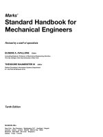
Some bearings
are
lubricated for life and not only do not
require relubrication but usually have no provision for
it.
This
typically applies to
small
bearings, and
the
life referred
to is the life of the lubricant-not necessarily the life of the
bearing. For other bearings, when new grease is added to
an operating bearing, the used grease condition and the
amount of grease added to start purging
of
the grease can
be used
as
a relubrication guide.
As
a general guideline, Fig-
ure
14
can be used and then modified by experience. The
20
000-
15000-
10000-
5
Doo-
3
mo-
2
000-
1500-
1000-
500-
C
t
chart
is
valid for stationary machines where loading con-
ditions
are
normal. The use of a good quality grease is as-
sumed, and the temperature should not exceed
160°F.
The
relubrication intervals should be halved for every
30°F
in-
crease
in
temperature above 16O"F, but the temperamre limit
of the grease must not be exceeded. When contamination
is
known
to be a concern, relubrication intervals should
be
reduced accordingly. The best protection for the bearings
is a good maintenance program.
a
RadialballMngs
b
Cylindrical
roller
bearings,
needle
roller
beadngs
c
Spherical
roller
bearings,
taper
roller
Wings,
thrust
ball
bearlngs
d
Rearing bore
diameter
-
nrlmin
Figure
14.
Relubrication interval
[lq.
(Courtesy
of
SKF
USA,
Inc.)
Cleanins, Preservation, and Storage
Bearings come from the manufacturer in a very clean
condition. They
are
usually coated with a preservative oil and
wrapped
in
special
corrosion-resistant
paper.
Bearings should
not
be
cleaned by the user before assembling them on a
ma-
chine unless something
has
happened to them after the
box
has been opened. Cleanliness in bearings
is
very important.
Tests have been done showing decreasing bearing life with
increasing
oil
contamination. New bearings should always
be
stored in their original packaging whenever possible.
If
bearings need
to
be cleaned,
the
chemicals used should
be
consistent
with
the bearing materials, especially the
cage. Many solvents can harm nylon or other types of non-
metal cages. For general cleaning, mineral spirits
is
rec-
ommended. Other solvents
will
work well on the
metal
parts,
but many have environmental drawbacks. After cleaning,
bearings
are
extremely vulnerable to corrosion and handling
damage. They should
be
dried
and coated with
oil
or
preser-
vative fluid as soon
as
possible.
If
compressed air is used
166
Rules
of
Thumb
for
Mechanical Engineers
to
dry
the bearing,
DO
NOT
allow the bearing to spin
under the force of the air. This is not only dangerous, but
serious damage to the bearing can result.
After
preserving,
the bearings should be wrapped in a neutral grease-proof
paper, foil, or plastic
film.
For a more detailed procedure
on
cleaning unshielded bearings, recommendations by
ABEC have been reproduced in the
SKF
Bearing Installa-
tion and Maintenance Guide
[
151.
When machinery with rolling element bearings is to be
idle for a long period of time, some extra measures should
be taken. Bearings should be relubricated before shut-
down.
No
rolling bearing lubricant has been developed
which will completely protect a bearing against moisture,
but some oils and greases are better than others. Com-
pounded oils and lithium base greases
are
more water-re-
pellent
than
others.
In
severe cases of bearings exposed
to
the elements for a long storage period, one method of pro-
tecting them is to completely
fill
the housing and bearing
with a good water-resistant grease. The only problem with
this
is that when
it
comes time to start the machine back up,
the excess grease must be removed first, or else some
means of allowing the housing and bearing to self-purge
without overheating the bearing must be used.
There are several different types of mounting methods
available for commercial bearings. These include collar
mounting, adapter sleeve, and direct press
fit,
both straight
and tapered bearing seat. Table
13
lists the advantages and
disadvantages of each kind.
The aspects of
shaft
quality that affect bearings
are
geo-
metric and dimensional accuracy, surface finish deflec-
tions, material, and hardness. The geometric accuracy in-
cludes not only the bearing seats but the shoulders. Because
the inner and outer rings of rolling element beatings
are
rel-
atively elastic, imperfections in the shafting and the hous-
ing can be translated directly to distortion of the bearing
raceways. This is especially true of shaft out-of-round-
ness, taper, and shoulder squareness.
A
shaft
that
is not
straight
can cause dynamic misalignment that severely in-
creases the bearing loading.
Although one of the advantages of using collar-mount-
ed bearings
is
the use
of
commercial shafting, some care
should
be
taken.
On
more critical applications, it is recom-
mended that turned, ground, and polished shafting
be
used.
Other commercial shafting is often quite a bit undersize and
can cause the collar
to
eventually come loose. It is
best
for
the
shaft
to
be no more than .001” undersize. The best
Table
13
Mounting Methods
Mounting Type Advantages Disadvantages
Eccentric locking Quick and
easy.
Least reliable, can
collar come loose.
Set screw locking
Can
use commercial
Set
screw slightly better.
collar shafting.
Adapter sleeve Can
use
commercial Bearing must have
shafting. tapered bore.
Positive mounting.
Not all bearings available
with a tapered bore.
Additional hardware
is
needed.
No accurate axial
location.
Press fit tapered
Ease
of mounting. Requires machined
bore
Ease
of
dismounting. tapered shaft bearing
Positive mounting. seat.
Bearing must have
tapered bore.
Not
all
bearings available
with a tapered
bore.
Press fit-straight Positive mounting. Precision machined
bore Easier to machine shaft
seat.
shaft.
Bearings
167
mounting for poor quality shafting is adapter sleeve mount-
ed bearings. For this type of mounting, the shaft can be up
to
.003”
to
.004”
undersize and still give a secure fit.
The surface roughness of the
shaft
may cause loss of
press
fits and excessive wear and fretting of the bearing seat (if
it
is
too rough).
A
maximum
limit for roughness on the
bear-
ing seat of
63
Ra
is recommended.
If
integral seals
will
also
contact the shaft surface, a finish between 10 and
20
Ra is
the maximum recommended.
Sometimes a
shaft
surface itself
is
used
as
the inner race-
way
of
the bearing. This is mainly true of cylindrical roller
bearings, although occasionally of other
types.
The most
common usage of
this
concept is for gearbox or transmis-
sion
applications
in which there
is
a gear on
the
shaft
between
two bearings. The advantage is that there
is
no need to
press fit
an
inner ring on the shaft, and the locknut and lock
washer usually associated with keeping the inner ring on the
shaft is not needed. The disadvantage is that the shaft race-
way
surface
has
to have the
same
tolerances and fin&% that
an actual inner raceway would have. This makes the shaft
difficult to make and costly, and can cause a maintenance
problem
if
the inner raceway fails on one end but the gear
and other raceway
are
still
good.
For this type of applica-
tion, the shaft raceways should have a surface hardness of
Rockwell
HRC
59
minimum, a maximum surface roughness
of 15 Ra, and freedom from objectionable lobing and wavi-
ness. Some manufacturers’ catalogs list the raceway diam-
eters needed for different
size
bearings.
The majority of bearings
are
mounted on a shaft with a
very close
or
interference fit. The contact pressure and
movement of the rollers on the inner or outer ring during
operation causes them
to
fm
and even creep around the shaft
or housing. The amount
of
press
or interference fit need-
ed varies considerably depending
on
the application. The
factors that must be considered are speed, load magnitude
and direction,
stiffness
of the supporting structure, and the
temperature range of the system. Shaft fits recommended
for various types of applications are listed in Table 14. In
Table 14
Selection of Shaft Tolerance Classifications for Metric
Radial Ball and Roller Bearings of Tolerance Classes ABEC-1, RBEC-1
CYLINDRICAL
I
ROLLER BEARINGS
DESIGN
&
OPERATING CONDITIONS
I
BALLBEARINGS
Inner Rina
1
Inner Ring must
1
;:htal
1
StatiOnaty
be easily axially
in Relation displaceable
All
Sizes
All
Sizes 96
to Load
HalW
1
96
1
1
Direction
I
Inner Ring need
displaceable
Heaw
[
All
Sizes
1
h6
1
All
Sizes
I
h6
All
Sizes
I
j6
I
Consult Bearing Manufacturer
I
Pure Thrust (Axial) Load
Dimensions
in inches
SPHERICAL
ROLLER BEARINGS
I
Tolerance
All
Sizes
All
Sizes
(1)
Tolerance Classifications shown are for solid steel shaff. Numerical values are listed in Table
15.
(2)
If greater accuracy is needed, substitute
j5,
k5
and m5 for
j6.
k6,
and m6 respectively.
Source:
ANSIIAFBMA
Sfd.
7-1988.
For hollow or nonferrous shafts, tighter fits may be needed.
168
Rules of Thumb for Mechanical Engineers
general, the higher the load, the heavier the press fit need-
ed.
This
same trend is true of speed. An interference fit is
generally recommended for the ring, which rotates relative
to the major load. A loose or slip fit is recommended for
the stationary ring. If the shaft is hollow, a heavier press fit
is usually needed. The fits in the table are valid for an
op-
erating temperature range between
32"
and
250°F
and
when the speed level
is
less than
600,000
DN.
The fit classes recommended in Table
14
refer to the
bearinghhaft diameter fits given in Table
15.
This table
gives the bearing bore and tolerance for commercial grade
(ABEC
1
and
RBEC
1)
bearings and the corresponding
shaft diameter tolerance from the nominal bearing bore for
a range of bearing sizes and fit classes. A complete listing
can be found in ANSUABMA Standard
7-1996 [6],
but
many bearing companies reprint portions of the listings in
their catalogs.
For unusual applications, it is necessary to calculate the
correct fit. These calculations are based on thin wall ring
theory.
In
general, some level
of
fit pressure must be main-
tained while at the same time the inner ring hoop stress is
within allowable limits. These limits are about
25
ksi for
rings made of through hardened material, and
35
ksi for
rings made from a carburizing or case-hardened steel.
Table 15
Shaft
Fitting Practice for Metric Radial Ball and Roller Bearings of Tolerance Classes ABEC-1, RBEC-1
Pad
II
Dimensions
in
Inches
Deviat~ons
and
Fits
in
.wO1
Inches
Bearings
169
Housings
The housing should provide a rigid support for the
bear-
ing. Housings may be separate components fastened to a
machine frame
or
foundation, or they may be an integral
part of the machine.
In
addition
to
supporting the load, the
housing protects the bearing and often provides other fea-
tures such as a lubricant reservoir, a lubricant flow system,
cooling, and seals.
There are
so
many things that affect the selection of a
housing that
it
is difficult to make any specific recom-
mendations. Table
16
lists many of the factors that may af-
fect the housing design or selection.
Bearing outside diameters
(O.D.)
are
held to tolerances
almost as close as the bores. A system of fits has been de-
veloped by the ABMA to provide flexibility in selecting
housing fits. Housing fits recommended
for
various
types
of
applications
are
listed in Table
17
(from
ANSVAFBMA
Standard
7-1996 [6]).
The class
of
fit is determined
by
the
nature of loading,
axial
movement requirements, temper-
ature conditions, housing materials, and design.
In most
cases, the outer rings are subjected
to
stationary loads that
permit a loose housing fit when matched with a tight shaft
fit. Fits must also account for differential thermal expan-
sion between the bearing and housing
so
that the bearing
O.D. is always able to move axially. However, a loose fit
should never be greater than necessary. Excessive loose-
ness results
in
less accurate shaft centering and addition-
al outer ring deformation under load.
The classes of fits referred to in Table
17
are
given
in
Table
18
for a limited range of bearing sizes.
ANSVABMA
Standard
7-1996 [6]
presents a wider range of bearing
sizes
as
well
as
additional fit classes. The bearing
O.D.
tol-
erances shown in the table are for standard commercial
(ABEC
1
or R.BEC
1)
bearings. Precision-class bearings
have tighter
O.D.
tolerances, and therefore, different fit
ranges. These
are
also given in the
ABMA
standards.
Table
16
Housing
Design
Considerations
Loading
Accuracy
______~
Magnitude
of
load variable or Axial control
of
shaft
Direction
of load:
variable or Radial
control
of shaft
Shock Bearinghousing fit
Vibration Squareness and concentricity
constant
constant
Environment Servicing and Maintenance
Corrosion resistance Installation problems
Radiation resistance
Heat and cold resistance
Magnetic permeabilii
Removal: frequent,
or
only at failure
Relubrication: regreasing
or
changing oil
~ ~~ ~
Styling,
Appearance,
and
Cost
Accessories
and Auxiliaries
Lubrication: grease
or
oil
Lube method circulating, bath,
Seals and sealing
Controls:
thermocouples, switches,
Housing: solid
or
two-piace
Construction: casting or
Weight: massive
or
light
design mist
fabrication
sensors
Source:
Link-Beit
Bearing
Technical
Journal
[I
l].
Again, many bearing companies include portions of these
tables in their catalogs.
In
most bearinglshaftmousing system,
it
is necessary to
have one
fxed
bearing to locate the
shaft,
and one expan-
sion bearing.
The
purpose of the expansion beating is to pre
vent preloading of the two bearings against each other.
This
is often accomplished
through
housing design. For ball
bearings and spherical roller bearings, this is done by using
a loose fit of the bearing,
in its housing
or
on the shaft.
170
Rules of Thumb for Mechanical Engineers
Outer
Ring
Axial
Displaceability
Table 17
Selection of Housing Tolerance Classifications for Metric Radial Ball and Roller Bearings
of
Tolerance Classes ABEC-1, RBEC-1
TOLERANCE
CLASSIFICATION
(1)
DESIGN
AND
OPERATING
CONDITIONS
Outer Ring
Rotating
in
relation to
load direction
~
Other
Conditions
Loading
Rotational
Conditions
not
recommended
Light
Normal or Heavy
Thin wall
split
Heavy housing not
Outer Ring
Stationat)!
in
relation
to load
direction
Heat input
through
Housing
split
Light
Normal
or
Heavy
Shock with
temporary complete
unloading
Load
Direction
indeterminate
Housing not
split
axially
I
G7(3)
H7
(2)
I-
Outer ring
easily axially
displaceable
I
Outer ring not
easily axially
displaceable
(1) For cast iron or steel housings. Numerical values are listed in Table18.
For
housings
of
non-ferrous alloys tighter fits may
(2)
Where wider tolerances are permissible, use tolerance classifications H8,
H7, J7. K7, M7.
N7
and
P7
in place
of
H7, H6,
(3)
For large bearings and temperature differences
between
outer ring and housings greater than 10 degrees
C,
F7
may be
(4)
The tolerance zones are such that outer ring may be either tight or
loose
in the housing.
Source:
ANSIIAFBMA
Std.
7-1988.
be needed.
J6,
K6,
M6, N6
and
P6
respectively.
used instead
of
67.
Bearings 171
172
Rules of Thumb for Mechanical Engineers
~~~ ~
Bearing Clearance
The establishment of correct bearing clearance is es-
sential for reliable performance of rolling element bearings.
Excessive bearing clearance will result in poor load
dis-
tribution within the bearing, decreased fatigue life, and
possible excessive dynamic excursions of the rotating sys-
tem. Insufficient bearing clearance may result in excessive
operating temperature or possible thermal lockup and cat-
astrophic failure.
Most bearings
are
manufactured with an initial radial in-
ternal clearance. This clearance is expressed over the di-
ameter. It is called radial clearance to distinguish it from
axial clearance or end play. The terms radial clearance and
diametral clearance are used interchangeably in the rolling
bearing industry. The
radial
internal clearance is defined by
the outer ring raceway contact
diameter
minus
the
inner
ring
raceway contact diameter minus twice the rolling element
diameter. This initial unmounted clearance is changed by
the shaft and housing fits, shaft speed, and by the thermal
gradients existing
in
the system and created by operation
of the bearing. After all of these factors have
been
consid-
ered, the bearing “operating clearance” should usually be
positive. The exception to this occurs with preloaded bear-
ings where the clearance has been carefully selected to
provide shaft control. Clearances of only
.O001”
or
.0002”
are
acceptable, but very small changes in thermal gradients
can eliminate such a clearance and cause problems.
Generally, higher speed bearings will need higher oper-
ating clearance to allow a margin for unknown
thermal
gra-
dients. Lower speed bearings, especially those with heavy
loads, will perform best with smaller operating clearance.
If
the housing
will
remain
much cooler than the bearing dur-
Table
19
Radial Internal Clearance
Classifications
ANSVABMA
Identification Code Internal
F~
2
0
3
4
Tight
Standard
Loose
Extra
loose
ing operation, extra clearance is often needed
to
account for
the fact that the shaft and inner ring will expand, while the
housing and outer ring will not. In general, ball bearings
need less operating clearance than do roller bearings. A rule
of thumb for minimum operating clearance of a cylindri-
cal roller bearing is
.0003”
to
.0005”.
Ball bearings can be
slightly less, and spherical roller bearings should be slight-
ly
more. The above considerations must be used to go
from an operating clearance
to
the unmounted internal ra-
dial clearance that must be obtained in the bearing.
After both the shaft and housing fits have been selected,
it is absolutely necessary to go back and review the internal
radial clearance of the bearings. If a relatively tight fit
has
been selected, a bearing with more
than
standard clearance
is usually needed. Interference
fits
always reduce the inter-
nal
clearance of the bearing. For bearings mounted on solid
shafts, the reduction in clearance will be about
80%-90%
of
the interference fit. For housings, this factor
is
about
90%
of
the
interference fit. These factors can change sigmkantly for
hollow shafts and thin section housings. Again, this can be
calculated by using thin ring theory.
The clearance manufactured
into
the unmounted bearing
has
been
stan-
by
ANSI/ABMA
in
Standard
20-1987
[
101
for ball and roller bearings (except tapers). For some
types
of bearings a
similar
format
is
used, but the
actual
val-
ues of clearance
are
selected by the manufacturer. Table
19
gives the radial internal clearance classifications. The in-
ternal fit refers
to
the relative amount of clearance inside
the bearing.
Tables
20
and
21
illustrate the
radial
internal clearance val-
ues for ball and roller bearings, respectively, established by
ANSUABMA.
A complete version of these tables can be
found in ANSUAFBMA Standard
20-1987
[
101.
Commer-
cial and precision bearings can normally be obtained
off
the
shelf with
the
clearances listed, although
tighf
and
extm
loose
bearings
are
not always stocked in all sizes. For
special
ap
plications, clearances other than those
listed
can be
ob-
tained on
special
order.
Special
clearances
are
not necessarily
more costly to make except that the quantity would be low
and delivery much longer. However, if the combination of
fits and
special
circumstances
of
operation
require
more
clearance than available in the standards, there is no alter-
native to getting
a
nonstandard clearance bearing.
Bearings 173
(Normal)
min.
ma.
1
5
1
5
1
7
2
8
2
0
2
0
2.5
9
3.5
11
4
12
4.5
14
6
16
7
19
7
21
8
24
10
28
Table
20
Radial Internal Clearance Values for Radial Contact Ball Bearings
min.
3
3
4
5
5
6
7
9
10
12
14
16
18
21
25
Clearance
values
in
0.0001
inch
d
I
SYMBOL2*
SYMBOLO'
I
SYMBOL3* SYMBOL 4* SYMBOL
5*
mm
I
-
max.
3
3
3.5
4
4.5
4.5
4.5
6
6
7
8
9
9
10
12
-
-
max.
9
9
10
11
11
13
14
17
20
23
26
32
36
40
46
-
-
over
2.5
6
10
18
24
30
40
50
65
80
100
120
140
160
180
-
-
I_
min.
-
6
7
8
9
11
12
15
18
21
24
28
32
36
42
-
11
13
14
16
18
20
24
28
33
38
45
51
58
64
0.5
0.5
*
These
symbols
relate
io
the
Identification
Code.
Source: ANSIIAFBMA
Std.
20-1987.
Table
21
Radial Internal Clearance Values for Cylindrical Roller Bearings
Clearance values in
0.0001
inches
d
mm
Tight
(2)'
Normal
(O)*
Loose
(3)*
Extra
Loose
(4)-
Over
Incl.
low
low
low
high
8
8
10
10
12
14
16
a
ia
20
24
26
30
32
35
39
43
47
53
high
12
12
12
14
16
ia
20
24
28
32
35
39
43
47
high
18
18
18
20
22
26
30
35
41
47
53
59
65
71
low
18
18
18
20
22
26
30
35
41
47
53
59
65
71
high
22
22
22
24
32
35
43
49
57
63
71
79
28
a7
14
14
14
16
18
20
22
32
37
41
45
49
55
28
10
18
24
30
40
50
65
100
120
140
160
180
200
225
250
315
355
a0
zao
4
4
4
4
5
6
6
10
10
12
14
14
16
a
ia
20
22
24
26
a
a
a
10
10
12
14
16
ia
20
24
26
30
32
10
ia
24
30
40
50
65
80
100
120
140
160
1
YO
200
225
250
280
315
These
symbols
relate
to
the Identification Code.
Source: ANSIIAFBMA
Std.
20-1987.
174
Rules
of
Thumb
for
Mechanical Engineers
Seals
Bearing seals have two basic functions: to keep conta-
minants out of the bearing and to keep the lubricant in the
bearing. The design of the seal depends heavily on exact-
ly what the seal is supposed to do. The nature of the con-
taminant, shaft speed, temperature, allowable leakage, and
type
of lubricant must be considered. Sealing can
be
an im-
portant consideration since in field use more bearings fail
from contamination than from fatigue. There
are
two
major
categories of seals: contact seals and clearance seals. Each
has its advantages and disadvantages for different appli-
cations. Contact seals vary widely from a simple felt strip
to precision face seals made flat to millionths of an inch.
In all cases, there is contact between moving and non-
moving surfaces, which provides a barrier to contaminants
and loss of lubricant. There is a tremendous variety of
ma-
terials and configurations used for contact seals.
The main limitation of contact seals is the sliding fric-
tion between the seal and shaft or rubbing surface. Seals for
commercial bearing application can use felt seals up to
500
to
1,000
feet per minute surface velocity. Lip seals, prob-
ably the most common contact seal, can be used up to
2,000
to
3,000
feet per minute with common materials, and
up to
5,000
feet per minute with special materials. Special
carbon circumferential seals and face seals can be used at
very high speeds, but these types of seals are very special
and not suitable for the average industrial application.
Lip seals are excellent for sealing solids, liquids, and
gases at reasonable pressures. The most common lip seal
material is Buna-N, a synthetic rubber compound. This is
the material usually used for bonded lip seals where a thin
rubber lip is attached
to
a metal holder and attached directly
to the bearing. It is also used in commercial cartridge-type
lip seals where the rubber
is
held by a metal case and a
spring is used to control lip pressure against the shaft. This
type of seal can have high torque and heat generation and
requires lubrication. For the effective application of lip
seals,
the rubbing surface roughness should be
10
to
20
Ra.
Smoother than this can result in leakage while rougher
can cause leakage
and
premature wear. Bearings with built-
in lip seals
already
have
this
type
surface ground on the bear-
ing. Housing seals usually rub
on the
shaft
itself, which must
have
a
smooth surface with no spiraling.
Labyrinth seals, often called clearance seals, do not have
rubbing contact between the seal and rotating member.
It
is this feature that gives them their principle advantage: no
frictional drag
or
heat generation. Because of this, they
are
the most commonly used
seal
for high speeds. Their dis-
advantage is that they cannot
be
used to seal against pres-
sure, and they are less effective against liquid and should
not be used when even partially submerged. Seal effec-
tiveness often depends on the availability of regular main-
tenance to keep the
area
around them clean and to lubricate
them where necessary. Grease combined with a labyrinth
seal can form a very effective barrier when properly main-
tained. Seal clearance must be carefully analyzed to keep
the seal gap
as
small
as possible but still maintain some gap
at all operating points.
To
retain
oil,
labyrinth
seals
may need
to
be
vented and usually must provide an oil return drain
within the seal.
For extreme sealing conditions, special seal designs
must be created. There is no exact formula for the design
of
special
sealing systems because the conditions
are
so
var-
ied. Engineering experience is the biggest factor, and con-
sulting with one of the bearing manufacturers that offers
sealed bearings or with a seal company is recommended.
One of the most common considerations is to use a com-
bination of two or more seals at
a
given location.
A
good
example is the Link-Belt DS grease-flushable auxiliary
seal shown in Figure
15.
Figure
15.
D8 Independently Flushable
Seal
[I
I].
(Cour-
tesy Link-Belt Bearing
Dig,
Rexnord
Corp.)
Bearings
175
SLEEVE BEARINGS
A
sleeve bearing (also called a journal bearing) is a sim-
ple device for providing support and radial positioning
while permitting rotation of a shaft. It is the oldest bearing
device known to man. In the broad category of sleeve bear-
ings can
be
included a
great
variety
of
materials, shapes, and
sizes. Materials used include an infinite number of metal-
lic alloys, sintered metals, plastics, wood, rubber, ceramic,
solid lubricants, and composites. Types range from a sim-
ple hole in a cast-iron machine frame to some exceedingly
complex gas-lubricated high-speed rotor bearings.
Sleeve bearings do have
a
number of advantages over
rolling element bearings,
as
well
as
some
disadvantages. Ad-
vantages are:
1. Inherently quiet operation because
there
are no mov-
2.
If
properly selected and maintained, they do not fail
3.
Wear is gradual, allowing scheduling of replacement.
4. Well suited
to
oscillating movement of the shaft.
5.
With proper material selection, excessive moisture
6.
With proper material selection, extreme temperatures
ing parts.
suddenly.
and submersion can be tolerated.
can be accommodated.
Disadvantages are:
1. High coefficient of friction.
2.
For the same boundary plan, much less load capacity.
3.
Life is not predictable except through experience.
In the application of sleeve bearings, the most important
factor is the selection of the actual bearing material. The
three most common industrial materials
are
babbitt, bronze,
and cast iron. After these, there is
an
amazing variety
of
dif-
ferent bearing materials, often specialized for a particular
application. In most cases, the details
of selection are
unique and assistance should
be
obtained from the manu-
facturer of the sleeve material.
Plain bearings made from babbitt are universally ac-
cepted
as
providing reasonable capacity and dependable
service, often under adverse conditions. Babbitt
is
a
rela-
tively soft bearing material, which minimizes the danger
of scoring or damage to shafts or rotors. It often can be re-
paired quickly on the spot by. for example, rescraping or
pouring of new metal. Ambient temperatures should not
exceed
130"F,
and the actual bearing operating tempera-
ture must not exceed
200°F.
Babbitt bearings
are
usually
restricted to applications involving light to moderate loads
and mild shock.
Bronze bearings
are
more suitable than babbitt for heav-
ier loads bearings
(75%
to
200%
higher), depending on
spe-
cific conditions of load and speed. Bronze withstands high-
er
shock
loads and
permits
somewhat higher speed operation.
It is usually restricted to
300°F
ambient temperatures if
properly lubricated. Bronze is a harder material
than
babbitt
and has a greater tendency to score or damage shafts in the
event
of
malfunction such
as
lack of relubrication. Field
re-
pair of bronze bearings generally
requires
removing
shims
and scraping
or
replacement of bushings. Bronze bushings
commonly are available in both cast and sintered forms.
Cast-iron bearings are generally low in cost and suitable
for many slow-moving
shafts
and oscillating or reciprocating
arms supporting relatively light loads. The lubricating
characteristics of cast iron are attributed to the free graphite
flakes present
in
the material.
With
the use of cast-iron bear-
ings, higher shaft clearance is usually utilized. Thus, any
large wear particles or debris will not join
or
seize the
beating.
This
material
has
been used to temperatures as high
as 1000°F (where ordinary lubricants are ineffective),
under light loads and slow speed intermittent operations.
Lubrication is just as important in sleeve bearings as it
is in rolling element bearings. There are three basic con-
ditions of lubrication for sleeve bearings: full film or hy-
drodynamic, boundary, and extreme boundary lubrication.
In full film lubrication, the mating surfaces of the shaft and
bearing material are completely separated by a relatively
thick film of lubricant. Boundary lubrication occurs when
the separating film becomes very thin. Extreme boundary
occurs when mating surfaces
are
in direct contact at vari-
ous high points. The first two categories give long bearing
life, while the third results in wear and shorter life.
In a full film bearing, the coefficient of friction is from
.001
to
.020,
depending on the mating surfaces, clearances,
lubricant type and viscosity, and speed. For a boundary lu-
bricated bronze bearing,
it
is
.OS
to .14. Friction in a bear-
176
Rules
of
Thumb
for
Mechanical Engineers
ing design is important because temperature and wear are
the longer the life of the bearing.
12
11
directly related to it. The lower the coefficient of friction,
Either
oil
or grease can
be
used for lubrication as long
as the temperature limitations for the grease or oil
are
not
exceeded. Oil viscosity should be chosen between 100 and
200
SUS
at
the estimated operating temperature. Grease is
the most common lubricant used for sleeve bearings,
main-
ly due to lubricant retention. Grease lubricated bearings usu-
ally operate with a boundary film. Many sleeve bearings use
grooving to improve lubrication on long sleeves. If the
sleeve length-to-diameter ratio is greater than 1.5: 1,
a
4
'8
groove should be used.
I
Under certain operating conditions, dry lubrication can
be used successfully with sleeve bearings. Graphited cast-
bearings
are
inaccessible
for
relubrication. Typical operating
'0
h
98
v)
CT
VI
8E
I
7s
s
v
6s
0
5i
E
3
2
1
0
bronze bearings are commonly used at elevated tempera-
tures, in low speed or high load applications, or where the
conditions for graphited bearings are
50
psi load with
speeds to
30
sfm or a maximum
PV
factor of
1,500.
There
are
a number of factors that combine to determine
the type of lubrication
a
bearing will have. Any of the fol-
lowing changes in the application would result
in
improved
lubrication and longer life:
A greater supply of lubricant available at the bearing
Increased shaft speed, which gives increased oil film
Reducing the load, which will increase the oil film
Better alignment
Smoother surface finishes
Use of a higher-viscosity lubricant
thickness
thickness
The load carrying ability of a sleeve bearing is usually
expressed in pounds per square inch (psi).
This
is calculated
by dividing the applied load in
pounds
by
the
projected
bear-
ing area in square inches. Projected bearing area
is
found
by multiplying the bearing bore diameter by the effective
length of the sleeve. Few industrial bearings
are
loaded over
3,000 psi, and most are carrying loads under
400
psi. With
cast-bronze sleeve bearings,
1,000
psi is acceptable. A us-
able
figure
for flat thrust washers is
100
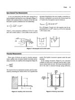
psi. Figure
16
shows
the maximum loads for various materials.
Another way of evaluating load capacity is through its
maximum
PV factor. The
PV
factor is the bearing load pres-
Figure
16.
Load
rating
of
three
common
bronzes.
Tem-
peratures
should
not
exceed
300°F
with
most
lubricants.
(From
1996
Power
Transmission Design
Hmdbookfl81).
sure times the surface velocity of the shaft in feet per
minute (sfm). For speeds above 200 sfm, use
a
PV
factor
of 20,000 for bronze sleeves and 10,OOO for babbitt sleeves.
Of course, there are maximum load limits and maximum
and minimum speed limits that must also be kept
in
mind
when using the
PV
factors.
PV
factors for other materials
should be obtained from the sleeve manufacturers.
Very careful shaft alignment is necessary during instal-
lation. Shaft journals must
turn
freely without binding in
the bearing, otherwise, excessive heat and seizure can re-
sult. Sharp edges on the shaft or the bearing surface can act
as scrapers to destroy lubricant films.
Do
not extend shaft
keyways into bearing bores. Shafting should
be
of the
proper size and fmish. Shaft diameters for rigid sleeve
bearing
units
are
usually held to the
regular
commercial tol-
erances
as
shown in Table 22.
Standard
shaft
surface rough-
ness of
32
Ra is acceptable for most applications. Graphit-
ed
sleeves should have shaft roughness reduced
to
12 Ra.
When picking the housing style, consider the direction
of
loading. Avoid loading cast-iron housings in tension,
whether one- or two-piece styles. If
this
cannot be avoid-
ed,
try
to obtain cast-steel housings.
Bearings
177
Table
22
Recommended Shaft Tolerances for Journal Bearings
Shaft
Diameters
Recommended Tolerance
Through
2”
Nominal
to
003“
Nominal
to
004”
Nominal
to
005”
Nominal
to
OM”
2%
through
4”
4%
through
6”
6x6
through
13”
From
Link-Belt
Technical Journal
fl
11.
1.
Lundberg, G. and Palmgren A., “Dynamic Capacity
of
Rolling Bearings,”
Acta Polytechnica,
Mechanical En-
gineering Series, Vol.
1,
No.
3,
Royal Swedish Acad-
emy
of
Engineering Sciences, Stockholm, 1947.
2. Lundberg,
G.
and Palmgren A., “Dynamic Capacity
of
Roller Bearings,”
Acta Polytechnica,
Mechanical En-
gineering Series, Vol. 2, No.
4,
Royal Swedish Acad-
emy of Engineering Sciences, Stockholm, 1947.
3. Anderson,
W.
J.,
“Bearing Fatigue Life Prediction,” Na-
tional
Bureau of
Standards,
No. 43NANB716211,1987.
4. American National Standard (ANSUAFBMA)
Std
1-
1990, “Terminology for Anti-friction Ball and Roller
Bearings and Parts.”
5.
American National Standard (ANSUABMA) Std
4-
1984, “Tolerance Defintions and Gaging Practices for
Ball and Roller Bearings.”
6. American National Standard (ANSVABMA)
Std.
7-
1996, “Shafting and Housing Fits for Metric Radial Ball
and Roller Bearings (Except Tapered Roller Bearings)
Conforming to Basic Boundary Plans.”
7.
American National Standard (ANSUAFBMA) Std
9-1990, “Load Ratings and Fatigue Life for Ball
Bearings
.”
8.
American National Standard (ANSUAFBMA) Std
11-1990, “Load Ratings and Fatigue Life for Roller
Bearings.”
9. American National Standard (ANSYAFBMA) Std 19-
1974, “Tapered Roller Bearings, Radial, Inch Design.”
10.
American National
Standard
(ANSUAFBMA)
Std
20-
1987, “Radial Bearings
of
Ball, Cylindrical Roller, and
Spherical Roller Types, Metric Design.”
11.
Bearing Technical Journal,
Link-Belt Bearing Div.,
Rexnord Corporation, 1982.
12. Ba~nbmga, E. N.,
et
al.,
Lye Adjustment Factors for Ball
and Roller Bearings-An Engineering Design
Guide,ASME,
New York, 1967.
13.
Harris,
T. A.,
Rolling Bearing Analysis.
New York
John
Wiley
&
Sons, Inc., 1966.
14.
Bearing Selection Handbook Revised-I
986, The
Timken
Co.,
1986.
15.
Bearing Installation and Maintenance Guide,
SKF
USA, Inc., 1988.
16.
MRC Aerospace Ball and Roller Bearings, Engineer-
ing Data Catalog,
SKF
USA, Inc., 1993.
17. Zaretsky, Erwin
V.
(Editor),
STLE Life Factors for
Rolling Bearings.
Society of Tribologists and Lubri-
cation Engineers, 1992.
18.1996
Power Transmission Design Handbook,
Penton
Publishing, Inc., copyrighted Dec. 1995.
Piping and Pressure
Vessels
R
.
R
.
Lee.
Vice President-International Sales. Lee’s Materials Services. Inc., Houston. Texas’
E
.
W
.
McAllister. P.E.,
Houston. Texas2
Jesse
W
.
Cotherman.
former Chief Engineer. Miller Pipeline Corp., Indianapolis. lr~d.~
Dennis
R
.
Moss.
Supervisor of Vessel Engineering. Fluor Daniel. Inc., Irvine. Calif.4
Process Plant Pipe
179
Definitions and Sizing
179
Pipe Specifications
187
Storing Pipe
188
Calculations to Use
189
Transportation Pipe Lines
190
Steel Pipe Design 190
Gas Pipe Lines
190
Liquid Pipe Lines
192
Pipe Line Condition Monitoring
195
Pig-based Monitoring Systems
195
Coupons
196
Manual Investigation
196
Cathodic Protection
197
Pressure Vessels
206
Stress Analysis
206
Failures in Pressure Vessels
207
Loadings
208
Stress
209
Procedure
1:
General Vessel Formulas
213
Procedure 2: Stresses in Heads Due to Internal Pressure 215
Joint Efficiencies (ASME Code)
217
Properties
of
Heads
218
Volumes and Surface Areas
of
Vessel Sections
220
Maximum Length
of
Unstiffened Shells 221
Useful Formulas
for
Vessels 222
Material Selection Guide
224
References
225
‘Process Plant Pipe
*Transportation Pipe Lines
4Pressure Vessels
2.
3Pipe Line Condition Monitoring
178
Piping
and
Pressure
Vessels
179
Standard pipe is widely used in the process industries
and is manufactured to ASTM standards (ANSI B36.10).
Pipe charts, such as the one in Table 1, and careful atten-
tion to purchase order descriptions when shipping or re-
ceiving pipe help achieve accurate results. A description
of piping, definitions, and how various types are manu-
factured follows.
Definitions and Sizing
Pipe Size
In pipe of any given size, the variations in wall thickness
do not affect the outside diameter
(OD),
just the inside di-
ameter
(ID).
For example, 12-in. nominal pipe has the
same
OD
whether the wall thickness is
0.375
in. or
0.500
in. (Refer to Table
1
for wall thickness of pipe).
Pipe length
Pipe
is
supplied and referred to as single random, dou-
ble random, longer than double random, and cut lengths.
Single
random
pipe length is usually 18-22 ft threaded
and coupled (TBEC), and 18-25
ft
plain end
(PE).
Double
random
pipe lengths average
38-40
feet.
Cut lengths
are
made to order within
-t.%-in.
Some pipe
is available in about
804
lengths.
The major
manufacturers
of pipe offer brochures on their
process of manufacturing pipe. The following descriptions
are
based upon vendor literature and specifications.
Seamless Pipe
This type of pipe is made by heating billets and ad-
vancing them over a piercer point. The pipe then passes
through
a
series of rolls where it is formed to a true round
and
sized to exact requirements.
Electric Weld
Coils or rolls of flat steel
are
fed
to
a
forming section
that
transforms the flat strip of steel into a round pipe section.
A
high-frequency welder heats the edges of the strip to
2,600”F at the fusion point. Pressure rollers then squeeze
the heated edges together to form a fusion weld.
Double Submerged Arc Weld
Flat
plate is used to make large-diameter pipe (20-in. to
44-in.) in double random lengths. The plate is rolled and
pressed into an
“0
shape, then welded at the edges both
inside and outside. The pipe is then expanded to the final
diameter.
Continuous Weld
Coiled skelp (skelp is semi-finished coils of steel plate
used specifically for making pipe), is fed into a flattener,
and welded
to
the trailing end
of
a preceding coil, thus form-
ing a continuous strip of skelp. The skelp travels through
a
furnace where it is heated
to
2,600”F and then bent into
an oval by form rollers. It then proceeds through a weld-
ing stand where the heat
in
the skelp and pressure exerted
by the rolls forms the weld. The pipe is stretched to
a
de-
sired
OD
and
ID,
and cut to lengths. (Couplings, if ordered
for any size pipe, will be hand tight only.)
Source
Lee, R. R.,
Pocket Guide to Flanges, Fittings,
and
Piping
Datu,
2nd
Ed.
Houston: Gulf Publishing Co., 1992.
180
Rules of Thumb for Mechanical Engineers
Table
1
Pipe Chart
Y8
,405
1
os
,049 .307
.I
863
40 40s
Std.
-068 ,269 .2447
80 80s
Ex.
Hvy.
.095 .215 -31 45
'14
.54
0
1
os
,065 .410 .3297
40 40s
Std.
,088 .364 .4248
80 80s
Ex.
Hvy.
,119
.302 .5351
3/e
,675
1
os
.065 .54
5
.4235
40 40s
Std.
.091 .493 .5676
80 80s
Ex.
Hvy.
.I26 .423 ,7388
Y2
840 5s .065 .710 -5383
1
os
.083 .674 ,671
0
40 405
Std.
.I
09 .622 .8510
80 80s
Ex.
Hvy.
,147 ,546 1.088
160
.i
88 .466 1.309
XX
Hvy.
,294 .252 1.71 4
3h
1.050 5s .065 .920 ,6838
1
os
.083 .884 ,8572
40 40s
Std.
.I
13 ,824 1.131
80 80s
Ex.
Hvy.
.I54 ,742 1.474
160
21
9 .614 1.944
XX
Hvy.
,308 .434 2.44
1
~~~ ~ ~~ ~~~~
1
1.315 5s ,065
1
.i
85 .8678
1
os
.I
09
1.097 1.404
40 40s
Std.
.I
33
1.049 1.679
80
80s
Ex.
Hvy.
.I79
.957 2.1 72
160
.250 .815
2.844
XX
Hvy.
.358 .599 3.659
Piping and Pressure Vessels
181
Table
1
(Continued)
Pipe Chart
1
Y4
1.660 5s .065 1.530
1.1
07
1
os
.lo9 1.442 1.806
40 40s
Std.
.140 1.380 2.273
80 80s
Ex. Hvy.
.191 1.278 2.997
160 .250 1.160 3.765
XX
Hvy
.382 .896 5.21 4
1
'/2
1
.goo
5s .065 1.770 1.274
1
os
.lo9 1.682 2.085
40 40s
Std.
.145 1.61
0
2.71 8
80 80s
Ex.
Hvy.
.200 1.500 3.631
160
.281 1.338 4.859
XX
Hvy.
.400
1.1
00
6.408
2
2.375 5s .065 2.245 1.604
1
os
.lo9 2.1 57 2.638
40 40s
Std.
.154 2.067 3.653
80 80s
Ex. Hvy.
.218 1.939 5.022
160
.344 1.689 7.462
XX
Hvy.
.436 1.503 9.029
2'12
2.875 5s .083 2.709 2.4 75
1
os
.120 2.635 3.531
40 40s
Std.
.203 2.469 5.793
80 80s
Ex. Hvy.
.276 2.323 7.661
160 .375 2.4 25 10.01
XX
Hvy.
.552 1.771 13.69
3
3.500 5s -083 3.334 3.029
1
os
.120 3.260 4.332
40 40s
Std.
.216 3.068 7.576
80 80s
Ex.Hvy.
.300 2.900 10.25
160
.438 2.624 14.32
XX
Hvy.
.600 2.300 18.58
(table continued
on
next page)
182
Rules
of
Thumb
for
Mechanical Engineers
Table
1
(Continued)
Pipe Chart
3%
4.000 5 5s .083 3.834 3.472
10 10s
.I
20 3.760 4.973
40 40s
Std.
.226 3.548 9.1 09
80
80s
Ex.
Hvy.
.318 3.364 12.50
XX
Hvy.
.636 2.728 22.85
4
4.500 5s .083 4.334 3.91 5
1
os
.I
20 4.260 5.61 3
40 40s
Std.
,237 4.026
10.79
80
80s
Ex.
Hvy.
.337
3.826 14.98
120
.438 3.624
19-00
160
.531
3.438 22.51
XX
Hvy.
.674 3.1 52 27.54
4
'/2
5.00
40
Std.
.247 4.506 12.53
80
Ex.
Hvy.
.355 4.290 17.61
XX
Hvy.
.710 3.580 32.43
5 5.563 5s
.I
09 5.345 6.349
1
os
,134 5.295 7.770
40 40s
Std.
.258
5.047 14.62
80
80s
Ex.
Hvy.
.375 4.81 3
20.78
120
.500 4.563
27.04
160
.625 4.31 3
32.96
XX
Hvy.
,750 4.063 38.55
~~
6
6.625 5s .lo9 6.407 7.585
1
os
.I
34 6.357 9.289
40
40s
Std.
.280 6.065
18.97
80
80s
Ex.
Hvy.
.432
5.761 28.57
120
.562
5.491 36.39
160
.719
5.1 89 45.35
XX
Hvy.
.864 4.897 53.1 6
Piping and Pressure Vessels
183
Table
1
(Continued)
Pipe Chart
7
7.625 40
Std.
,301 7.023 23.57
80
Ex.
Hvy.
500
6.625 38.05
XX
Hvy.
.875 5.875 63.08
8
8.625
5s
1
os
20
30
40 40s
Std.
60
80
80s
Ex.
Hvy.
100
120
140
160
XX
Hvy.
.lo9
.148
.250
.277
.322
.406
500
.594
.719
.812
.875
.906
8.4 07
8.329
8.1 25
8.071
7.981
7.81 3
7.625
7.439
7.1
89
7.001
6.875
6.81 3
9.91 4
13.40
22.36
24.70
28.55
35.64
43.39
50.95
60.71
67.76
72.42
74.69
9 9.625 40
Std.
.342 8.941 33.90
80
Ex.
Hvy.
500
8.625 48.72
XX
Hvy.
.875 7.875 81.77
10 10.750
5s
1
os
20
30
40 40s
Std.
60
80s
Ex.
Hvy.
80
100
120
140
160
.134
.165
.250
.307
.365
SO0
.594
.719
.844
1
.ooo
1.125
10.482
10.420
10.250
10.1 36
10.020
9.750
9.564
9.31 4
9.064
8.750
8.500
~~~~
15.1 9
18.70
28.04
34.24
40.48
54.74
64.43
77.03
89.29
104.13
11
5.64
11
11.750 40
Std.
.375
1
1
.ooo
45.55
80
Ex.
Hvy.
500
10.750 60.07
XX
Hvy.
.875 10.000 101.63
(table continued
on
next page)
184
Rules of Thumb for Mechanical Engineers
Table
1
(Continued)
Pipe Chart
12 12.750
5s
1
os
20
30
40
60
80
100
120
140
160
40s
Std.
80s
Ex.
Hvy.
.165
.180
.250
.330
.375
.406
SO0
.562
-688
.844
1
.ooo
1.1 25
1.312
12.420
12.390
12.250
12.090
12.000
1 1.938
1 1.750
1 1.626
1
1.376
11.064
10.750
10.500
10.1 26
22.1 8
24.20
33.38
43.77
49.56
53.52
65.42
73.1
5
88.63
107.32
125.49
139.67
160.27
14 14.000 10
20
30
40
60
80
100
120
140
160
-250
.312
Std.
.375
.438
Ex.
Hvy.
.500
.594
.750
1.094
1.250
1.406
-938
13.500
13.376
13.250
13.1 24
13.000
12.814
12.500
12.1 26
11.814
11
SO0
11.188
36.71
45.6
1
54.57
63.44
72.09
85.05
106.1 3
130.85
150.9
170.21
189.1
16
16.000 10
20
30
40
60
80
100
120
140
160
.250
.312
Std.
.375
Ex.
Hvy.
500
.656
.844
1.031
1.21
9
1.438
1.594
15.500
15.376
15.250
15.000
14.688
14.314
13.938
13.564
13.1 24
12.814
42.05
52.27
62.58
82.77
107.5
136.61
164.82
192.43
223.64
245.25
Piping and Pressure Vessels
185
Table
1
(Continued)
Pipe Chart
30
40
60
80
100
120
140
160
250
.312
Std.
.375
.438
Ex.
Hvy.
SO0
.562
,750
.938
1
.I
56
I
.375
1.562
1.781
17.500
17.376
17.250
17.1 24
17.000
16.876
16.500
16.1 26
15.688
15.250
14.876
14.438
47.39
58.94
70.59
82.1
5
93.45
104.67
138.1 7
170.92
207.96
244.1 4
274.22
308.5
20 20.000
10
20
30
40
60
80
100
120
140
160
.250
Std.
.375
Ex.
Hvy.
.500
594
.812
1.031
1.281
I
SO0
1.750
1.969
19.500
19.250
19.000
18.814
18.376
17.938
17.438
17.000
16.500
16.064
52.73
78.60
104.1 3
123.1
1
166.4
208.87
256.1
296.37
341 -09
379.1 7
22
22.000
10
20
30
60
80
100
120
140
160
.250 21.500
Std.
.375 21.250
X
Hvy.
SO0
21
.ooo
-875 20.250
1.1
25 19.750
1.375 19.250
1.625 18.750
1.875 18.250
2.1 25 17.750
58.07
86.61
1
14.81
197.41
250.81
302.88
353.61
403.0
451.06
24 24.000 10
.250 23.500 63.41
20
Std.
-375 23.250 94.62
Ex.
Hvy.
SO0
23.000
125.49
(table
continried
on
next
page)
186
Rules of Thumb for Mechanical Engineers
Table
1
(Continued)
Pipe
Chart
30
40
60
80
100
120
140
160
.562
.688
.969
1.219
1.531
1.81 2
2.062
2.344
22.876
22.626
22.064
21.564
20.938
20.376
19.876
19.314
140.68
171.29
238.35
296.58
367.39
429.39
483.1
542.1 3
26 26.000 10
,312 25.376 85.60
Std.
.375 25.250 102.63
20
X
Hvy.
SO0
25.000 136.1 7
28 28.000 10
,312 27.376 92.26
Std.
'375 27.250
1
10.64
20
SO0
27.000 146.85
30
.625 26.750 182.73
30 30.000 10
.312 29.376 98.93
Std.
.375 29.250
1
18.65
30
.625 28.750 196.08
20
Ex.
Hvy.
.500 29.000 157.53
32 32.000 10
.312 31.376 105.59
Std.
,375 31.250 126.66
20
SO0
31
.OOO
168.21
30
.625 30.750 209.43
40
.688 30.624 230.08
34 34.000 10
.312 33.376
11
2.25
Std.
.375 33.250 134.67
20
SO0
33.000
1
78.89
40 .688 32.624 244.77
30 .625 32.750 222.78
36 36.000 10 .312 35.375
11
8.92
Std.
,375
35.250
142.68
Ex.
Hvy.
.500 35.000 189.57
Piping and Pressure Vessels
187
Table
1
[Continued)
Pipe Chart
166.71
221.61
276.1
8
330.41
1
~~~ ~~ ~~
42.000
Std.
.375 41.250
20
X
Hvy.
500
41.000
30 .625 40.750
40 ,750 40.500
48
48.000
Std.
,375 47.250
1
90.74
X
Hvy.
,500 47.000 253.65
Data in Table
1
courtesy
of
Tioga Pipe Supply Company.
Pipe Specifications
ASTM A-1
20
Sizes %-in. to 16-in. standard weight, extra strong, and
double extra strong (Std. Wt.,
XS,
XXS).
The specification
covers black and hot-dipped galvanized welded and seam-
less average wall pipe for use in steam, gas, and air lines.
Markings.
Rolled, stamped or stenciled on each length
of
pipe: the brand name, ASTM A-120, and the length of
the pipe. In case
of
bundled pipe, markings will appear on
a tag attached to each bundle. Table 2 shows a bundling
schedule.
ASTM A-53
Sizes %-in. to 26-in., standard weight, extra strong, and
double extra strong, ANSI schedules
10
through 160 (see
Table
1
for ANSI pipe schedules). The specification cov-
ers
seamless and welded black and hot-dipped galvanized
Table
2
Bundling Schedule
30
630
24 504
18
378
12 252
7 147
5
105
3
63
3
63
151
212
215
214
166
176
144
172
630
504
378
252
147
105
63
63
195
272
280
275
216
228
189
229
average wall pipe for conveying oil, water, gas, and pe-
troleum products.
Markings.
Rolled, stamped or stenciled with brand name,
kind, schedule, length
of
pipe, and type of steel used.
In
case
of bundles, markings will appear
on
a bundle tag.
188
Rules
of
Thumb
for
Mechanical Engineers
ASTM
A-106
Sizes
X
to 26-in., ANSI schedules to 160. The specifi-
cation covers seamless carbon steel average wall pipe for
high-temperature service.
Markings.
Rolled, stamped or stenciled with brand name,
type such as ASTM A-l06A, A-l06B, A-106C (the A,
B,
C,
indicate tensile strengths and yield point designations),
the test pressure, and length
of
pipe. In case of bundles, the
markings will appear on a bundle tag.
API-51
Sizes
%in.
to 48-in., standard weight through double extra
strong. The specification covers welded and seamless pipe
suitable for use in conveying oil, water, and gas.
Markings.
Paint stenciled with brand name, the API
monogram, size, grade, steel process, type of steel, length,
and weight per foot on pipe 4-in. and larger. In case of bun-
dles, the markings will be on the bundle tag. Couplings, if
ordered, will be hand tight.
Source
Lee,
R. R.,
Pocket Guide to Flanges, Fittings, and Piping
Data,
2nd Ed. Houston: Gulf Publishing Co., 1992.
Storing
Pipe
Step l-Pipe
Racks
Figure 1 shows a pipe rack made by using 12
x
12411.
tim-
bers. The rack has been assigned a number for materials ac-
-
counting purposes.
Do
not store pipe directly on the ground.
If rack materials are not available, then use the pipe itself
by preparing a rack from the pipe with
a
few boards under
each end.
Step
24ayers
Form
the first layer of pipe with one end straight, and
other joints straight across the rack. Secure the stack by nail-
ing wooden blocks to the sills, against the side of the pipe
on the inside edges (see Figure 1).
Step
3-Measure
Tally each joint
of
pipe in the layer. Use a paint stick
or
suitable marker to mark each joint according to length, size,
schedule, and purchase order item number.
Figure
I,
Schematic of rack for storing
pipe.
Piping and Pressure
Vessels
189
Total
the footage on the layer of pipe, and then
mark
the
total footage and number of joints on the outside pipe for
future
inventory purposes. Apply color codes
to
pipe at
this
time if applicable.
step
44unnage
Apply sufficient dunnage of
the
same
thickness
across
the
pipe with wooden blocks nailed to one side. Stack the next
layer of pipe directly over
the
first
layer
with
the stmight ends
in line with each other. Then follow steps 2,3, and
4.
Continue to follow
the
steps until the rack is considered
full
by the supervisor.
Rules
for
Storing
Pipe
1.
Do
not
mix
pipe sizes and schedules on the same
pipe rack.
2. Keep the pipe storage area clean
to
prevent accidents.
3.
Do
not crowd the storage areas. Leave mom
for
large
trucks and cranes.
4. Make a physical count of the pipe on a weekly or
monthly basis to verify your materials accounting
records
as
correct.
5.
Always measure pipe within tenths of an inch. Mea-
sure
the entire length of pipes, including couplings and
threads.
Source
LAX,
R.
R.,
Pocket Guide to Flanges, Finings, and Piping
Data,
2nd
Ed.
Houston: Gulf Publishing
Co.,
1992.
Calculations
to
Use
If the outside diameter
(OD)
and the wall thickness of a
pipe (t) are known, then
you
may
calculate the weight per
foot with the following equation:
Weight per foot
=
10.68
x
(OD
-
t)
x
t
Example:
What
is
the weight per foot of a 3-in. pipe with
a .216-in. wall thickness and an
OD
of 3.500 in.? Using the
equation,
Weight per foot
=
10.68
x
(3.500
-
.216)
x
.216
=
7.58 lbdft
Another method to determine weight per foot of pipe
where the outside diameter and wall thickness are known
is
called
the
Baiamonte plate method.
It
is
based
on
a
square foot of plate 1 inch thick weighing 40.833 lbs, and
uses the following equation:
Weight per foot
=
40.833
x
(Oy)
-
x
lr
x
t
Example:
What is the weight per foot
of
an
8-in. pipe with
a wall thickness of .322 in.? Table
1
shows that an 8-in. pipe
has an
OD
of 8.625
ins.
So,
using the equation,
Weight per foot
=
40.833
x
(
8m62:i
'322)
x
3.1416
x
t
=28.58lbs/ft
Source
Lee,
R.
R.,
Pocket Guide to Flanges, Fittings,
and
Piping
Data,
2nd
Ed.
Houston: Gulf Publishing
Co.,
1992.