Rules of Thumb for Mechanical Engineers 2010 Part 17 ppt
Bạn đang xem bản rút gọn của tài liệu. Xem và tải ngay bản đầy đủ của tài liệu tại đây (905.11 KB, 18 trang )
390
Rules
of
Thumb
for
Mechanical Engineers
XYZ
Company
Balance Sheet
As
of
March
31, 1994
ASSETS
Current Assets:
Cash
$25,000.00
Accounts Receivable
$268,000.00
Inventory
$1
63,000.00
Total CurrentAssets
$456,000.00
Property, Plant &Equipment
Building
$600,000.00
Equipment
$300,000.00
Land
-
$100,000.00
less Accumulated Depreciation
(
$250,000.00) $350,000.00
less Accumulated Depreciation
($1
25,000.00) $1 75,000.00
Toial
Properly, Plant
&
Equipment
$625,000.00
To tal Assets
81,087,LkXl.tW
Liabilities
Current Liabilties:
Accounts Payable
Salaries Payable
Interest Payable
Income Tax Payable
Total Current Liabilities
Notes Payable
Long-
Term Liabilities:
Total Liabilities
$275,000.00
$1
95,000.00
$1
3,000.00
$36,000.00
$519,000.00
$260,000.00
$779,000.00
owner’s
tstockholder’s)
Capital
Stock
$200,000.00
Retained Earnings
$102,000.00
Total
Owneris Equity
$302,000.00
$1,08l,~.tW
Total Liabilities
&
Owner’s Equity
tal
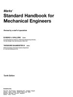
by expensing the portion of each asset “consumed”
during each income statement’s time period. Depreciation
is a
noncash expense,
since no cash
flow
actually
occurs
to
pay for this expense. The
book
value
of an asset is shown
in the balance sheet, and is simply the purchase price of the
asset minus its accumulated depreciation. There
are
several
methods used to calculate depreciation, but the easiest and
most frequently used method is
straight-line depreciation,
which is calculated with the following formula:
Cost
-
Salvage Value
Expected Life of Asset
Depreciation Expense
=
Straight-line depreciation allocates
the
same amount
of
depreciation expense each year throughout the life of the
asset.
SaZvage value
(residual value) is the amount that a
company can sell (or
trade
in)
an
asset for at the end of its
useful life. “Accelerated” depreciation methods (such as
sum-of-the-yearsy-d&ts and
declining
balance methods)
are
available and
may
sometimes
be
used to expense the cost
of
an asset faster
than
straight-line depreciation. Howev-
Engineering Economics
391
XYZ
Company
Income
StaWnent
For
the
Quar&r
Ended
Mbrch
31,
1994
Sales Revenues
Less: Cost
of
Goods
sold
Gross Margin
Less: Operating Expenses
Selling expenses $295,000.00
Salaries expense
$526,000.00
Insurance expense 832,000.00
Property Taxes
$27,000.00
Depreciation, Building
$70,000.00
Depreciation, Equipment $35,000.00
Income from Operations
Other
Income
Sale
of
Assets $1
6,000.00
Interest Revenue
$2,000.00
Less: Interest Expense
Income before Taxes
Less: lnwme Tax Expense
Net
Income
$2,450,000.00
(
81,3~,~.~1
$1,075,000.00
($985,000.001
$90,000.00
$1
8,000.00
$108,O00.00
($22,0.001
$86,o0O.00
(
$34,400.001
$5
1,,6yx) OO
XYZ
Company
Statement
of
Changes in Retained Earnings
For
the
Quamr
Ended
Mbrch
31,
1994
Retained Earnings, Dec. 31,1993
$50,400.00
Net Income, Quarter 1,1994
Retained Earnings, March 31,
1994
er, the use
of
accelerated depreciation methods is gov-
erned by the tax laws applicable to various types of assets.
A
recent accounting textbook and tax laws can
be
consulted
for further information about the use
of
accelerated de-
preciation methods.
The pfit (or
loss)
for the time
period
of
the income
state-
ment
is
carried over as retained earnings and added to (or
subtracted from) owner’s equity, in the “statement of
changes in retained earnings” illustration.
If
the company paid out any dividends to its
stuckholders
dur-
ing this time
period,
that amount would
be
shown
as
a
de-
duction to retained earnings
in
this financial statement.
This
new retained earnings amount is also reflected
as
the retained
earnings account balance in the current balance sheet.
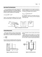
The last financial statement is the
statement
of
cash
flows, which summarizes the cash inflows and outflows of
the company (or other accounting entity) for the same time
period as the income statement. This statement’s purpose
392
Rules
of
Thumb
for
Mechanical Engineers
Statement
Of
c8Sb
FIOHW
For
the
Quartet
Ended
Mrch
31,194
Net
hcome
$51,600.00
Adjustments
to
reconcile
net
income
to
cash flowfrom op. advities:
Decrease in accounts receivable
$5,000.00
Increase in inventory
(
$1
5,000.00)
Increase in accounts payable $25,000.00
Decrease in salaries payable $5,000.00
Depreciation expense, equipment
$35,000.00
Depreciation expense, building $70,000.00
Total
Adjustments: $1 25,000.00
Net
cash
ffo
w
Iiom
opefating
ac6vi~es:
Sl76,sOo.al
is to show where the company has acquired cash (inflows)
and to what activities its cash has been utilized (outflows)
during this time period. The statement divides and classi-
fies cash flows into three categories:
(1)
cash provided by
or used by operating activities;
(2)
cash provided by
or
used
by investing activities; and
(3)
cash provided by or used by
financing activities. Cash flow from operations is the cash
generated (or lost) from the normal day-to-day operations
of a company, such
as
producing and selling goods
or
ser-
vices. Cash flow from investing activities includes selling
or purchasing long-term assets, and sales or purchases of
investments. Cash flow hm financing activities covers the
issuance of long-term debt or stock to acquire capital, pay-
ment of dividends
to
stockholders, and repayment of prin-
cipal on long-term debt.
The statement
of
cash flows complements
the
income
Statement,
because
although income and
cash
flow
are
related,
their
amounts
are
seldom equal. Cash flow is also a better
measure
of a company’s performance than net income, be-
cause net income relies upon arbitrary expense allocations
(such
as
depreciation expense). Net income can also be
ma-
nipulated by a company (for example, by reducing
R&D
spending, reducing inventory levels,
or
changing accouflting
methods to make
its
“bottom
lie”
look
better in the short-
term. Therefore, analysis of
a
company’s cash flows and cash
flow trends is frequently the best method
to
evaluate a com-
pany’s performance. Additionally, cash flow
rather
than
net
income should
be
used to determine the
rate
of
return
earned
on
the initial investment, or
to
determine the value of a
company
or
financial project. (Value is determined by
dis-
counting cash flows at the
required
rate of
return.)
The statement of cash flows can be prepared directly by
reporting a company’s
gross
cash inflows and outflows
over a time period, or indirectly by adjusting a company’s
net income to net cash flow for the same time period. Ad-
justments to net income are required for
(1)
changes in as-
sets
and
liability
account
balances,
and
(2)
the
effects
of
non-
cash revenues and expenses
in
the income statement.
For example, in comparing
XYZ
Company’s current
balance sheet with the previous quarter, the following in-
formation is obtained about current assets and liabilities:
Cash increased by
$10,000
Accounts receivable decreased by
$5,000
Inventory increased by
$15,000
Accounts payable increased by
$25,000
9
Salaries payable increased by
$5,000
Additionally, the balance sheets show
that
the company has
paid
off
$166,600
of long-tern debt this quarter. This in-
-
Cash
flow
from financing activities:
Retirement
of
longkrm
debt
(notes
payable)
Net
cash
flow
hm
financing
acUviiies:
($1
66,600.00)
($1
66,m.00
Net
hcreese
in
cash:
$10,000.00
81 5,000.00
$25,000.00
Cash account balance, Dec. 31,1993
Cash account balance, March 31,1994
Engineeting Economics
3Q3
formation from the balance sheets, along
with
the non-
cash expenses (depreciation) from
the
current
income
state-
ment,
are
used
to
prepare
the “statement of
cash
flows.”
The
example demonstrates the value of the statement of cash
flows because it shows precisely the sources and uses of
XYZ Company’s cash. Additionally, it reconciles the cash
account balance hm the previous quarter to
the
amount on
the
current quarter’s balance sheet.
Engineering Economics
1.
Newman,
D.
G.,
Engineering Economic Analysis.
San
Jose, CA Engineering
Press,
1976.
2.
Canada, J. R. and
White,
J.
A.,
Capital Investment De-
cision Analysis
for
Management and Engineering.
En-
glewmd Cliffs, NJ: PrenticeHall,
1980.
3.
Park,
W.
R.,
Cost Engineering Analysis: A Guide
to
Economic Evaluation
of
Engineering Projects,
2nd
ed.
New York Wiley,
1984.
4.
Taylor,
6.
A.,
Managerial
and
Engineering Economy:
Economic Decision-Making,
3rd
ed.
New York: Van
Nostrand,
1980.
5.
Riggs, J:
L.,
Engineering Economics.
New York Mc-
6.
Barish, N.,
Economic Analysis
for
Engineering and
Managerial Decision Making.
New York: McGraw-
Hill,
1962.
Graw-Hill,
1977.
Finance
1.
Bdey, R. A. and
Myers,
S.
C.,
Principles
ofcorporate
2.
Kroeger,
H.
E.,
Using Discounted Cash Flow Efective-
Finance,
3rd ed. New York McGraw-Hill,
1988.
Zy.
Homewood,
IL:
Dow Jones-Irwin,
1984.
Accounting
1.
Chasteen,
L.G.,
Flaherty, R.E., and O’Conner,
M.C.
In-
termediate Accounting,
3rd ed. New
Yo&
McGraw-
Hill,
1989.
2.
Eskew, R.K.
and
Jensen,
D.L.,
Financial
Accounting,
3rd
ed.
New York Random House,
1989.
Addltional References
Owner’s Manual
from
any Hewlett-Packard, Texas In-
struments, or other
make
businesdfmancial calculator.
Note:
A
business or financial calculator is an
absolute
must
for those serious about analyzing investments and fi-
nancial
projects
on anything
more
than
an occasional basis.
In
addition to performing simple
PV,
FV,
and mortgage or
loan payment calculations, modem financial calculators can
instantly calculate
NPVs
and
IRRs
(including multiple
roots)
for the most complex cash
flow
problems. Many cal-
culators can also tabulate loan amortization schedules and
depreciation schedules, and perform statistical analysis on
data. The owner’s manuals
from these calculators
are
ex-
cellent resources and give numerous examples of how
to
solve and analyze various investment problems.
Appendix
Laurence
D.
Morris,
Senior Technical Marketing Engineer-Large Commercial Engines,
Allison
Engine Company,
Rolls-Royce Aerospace Group
Conversion
F~C~O~S "
395
Decimal
Multiples
and
Fractions
of
SI
units ,
399
Systems
of
Basic
Unifs
399
Temperature Conversion Equations
399
394
Appendix
395
Category
Multiply
BY
To
Obtain
Acceleration
Angle
Area
Density
EnergyNVork
ft/sec2
in/sec2
m/sec2
m/sec2
degrees
degrees
degrees
degrees
minutes
radians
revolutions
seconds
ft2
in2
yard2
mile2
acres
m2
m2
m2
m2
m2
acres
acres
acres
acres
gram/cm3
ibrn/ft3
Ib,,.Jgallon
(U.S.
liquid)
sluglft3
kg/m3
kg/m3
kg/m3
kg/m3
Btu
erg
ft-lb
kilowatt-hour
calorie
newton-meter
watt-second
joule
ioule
0.3048
0.0254
3.2808
39.3701
6.0000
1.745328
x
1
0-2
2.777778
x
1
0-3
3600.00
0.1 667
57.2958
360
2.77778
x
1
0-4
0.0929
6.451 6
x
1
0-4
0.8361
2.590
x
1
O6
4.047
x
1
O3
10.7643
1550.0
1.1
960
3.861
0
x
1
0-7
2.471
x
0.4047
4.356
x
1
O4
4.047
x
1
O3
1.562
x
1
0-3
1000
16.01 85
11
9.826
51 5.379
0.001
0.0624
8.3454
x
1
0-3
1.9403
x
1
0-3
1055.06
1.3558
3.600
x
1
O6
4.1
859
1
.ooo
1
.ooo
9.4781
x
1
0-4
1
.ooo
x
I
0-7
1.000
x
107
m/sec2
m/sec2
ft/sec2
in/sec2
minutes
radians
revolutions
seconds
degrees
degrees
degrees
degrees
m2
m2
m2
m2
m2
ft2
1n2
yard2
m11e2
acres
hectares
ft2
m2
m11e2
kg/m3
kg/m3
kg/m3
kg/m3
gram/cm3
ibrn/ft3
IbJgallon
(U.S.
liquid)
slug/ft3
joule
joule
joule
joule
joule
joule
joule
Btu
erg
(table
continued
on
next
page)
396
Rules of
Thumb
for Mechanical Engineers
Category
Multiply
BY
To
Obtain
EnergyNVork (cont'd) joule
joule
joule
joule
joule
joule
Btu
kilowatt-hours
Btu
calorie
kilowatt-hour
ft-lb
Force
Length
Mass
Moment (Force)
dyne
pound
(Ib)
newton (N)
newton
foot
(ft)
inch (in)
yard
micron
mile (mi)
mile, nautical (nm)
meter (m)
meter
meter
meter
meter
meter
mile, nautical (nm)
mile
mile
mile
pound mass
(Ib,)
slug
ounce
ton (metric)
ton
(2000
Ib,)
kilogram (kg)
kilogram
kilogram
kilogram
kilogram
pound mass
ounce
fOOt-pOUtId
(ft-lb)
dyne-centimeter
newton-meter (N-m)
0.7376
2.7778
x
1 0-7
0.2389
1
.ooo
1
.ooo
2.930
x
1
O-"
341 2.97
253.0
2.655
x
1
O6
3.766
x
1 0-7
1.000
x
107
3.953
x
I
0-3
1
-000
x
10-5
1.000
x
105
4.4482
0.2248
0.3048
2.540
x
1
0-2
0.91 44
1
.ooo
x
10-6
1.6093
x
1
O3
1.8520
x
1
O3
3.2808
39.3701
1.0936
1
.ooo
x
106
6.21 39
x
1
O4
5.3996
x
1
O-"
1.1 5076
0.86896
5280
1760
0.4536
14.5939
2.83495
x
1
0-2
1000.00
907.1 85
2.2046
0.0685
35.2739
0.001
0
1 .I 023
x
1
0-3
16
0.06250
1.35582
0.73756
I
.ooo
x
I
0-7
ft-lb
kilowatt-hour
calories
newton-meter
dyne centimeters
watt-second
kilowatt-hours
Btu
calories
Btu
kilowatt-hour
ft-lb
newton (N)
newton
dyne
pound
(Ib)
meter (m)
meter
meter
meter
meter
meter
foot
(ft)
inch (in)
yards
micron
mile (mi)
mile, nautical (nm)
mile
mile, nautical
foot
yard
kilogram (kg)
kilogram
kilogram
kilogram
kilogram
Ibm
slug
ounce
ton (metric)
ton
(2000
Ib,)
ounce
pound mass
newton-meter (N-m)
N-m
foot-pound
(ft-lb)
dyne-centimeter
newton-meter
1
.ooo
x
107
Appendix
397
Category
Multiply
BY
To
Obtain
Moment of Inertia (Area) metel4
foot4
metel4
in4
Moment of Inertia (volume) mete6
foot5
mete6
in5
Moment
of
Inertia (Mass) m2-kg
m2-kg
in2-lb
ft2-lb
Power
Pressure and Stress
Btu/hour
erglsecond
ft-1
blsecond
horsepower (HP)
calories/second
joulelsecond
watt
(W)
watt
watt
watt
watt
watt
ft-lb/second
horsepower
ft-l
b/second
calories/second
horsepower
Btu/minute
atmosphere
bar
cm.
of
Hg
(0%)
in. of Hg
(0°C)
in. of
H20
(4°C)
dyne/cm2
Ib/ft2
Ib/in2 (psi)
kilogram/cm2 (kg/cm2)
newton/meteP
(n/rn2)
pascal (Pa)
pascal
pascal
pascal
pascal
pascal
pascal
1
15.861 8
8.63097 x
10s
2.40251 x
lo6
4.1 6232 x
1
0-7
380.1 239
2.63072 x
1
Os
9.45870 x
1
O7
1.05723 x
1
O4
23.73034
4.21 401 3 x
1
C2
341 7.1 71
2.926397
x
1
O4
0.29307
1.35582
745.699
4.1
86
1
.ooo
3.41 21 4
0.737562
1.34102
x
103
0.2389
1.000
1.818 x
los
550.06
0.32394
3.087
42.426
0.02357
1.000
x
10-7
1.000
x
107
1.01325~10~
1333.22
3.386 x
1
O3
249.1
0
0.1 0000
47.88026
6894.757
9.8067 x
1
O4
1
.ooo
1
.ooo
9.86923
x
10-B
1.000 x
10s
7.50064 x
1
O4
2.953 x
10"'
4.01 4 x
1
O3
10.000
1.000~105
foot4
meteP
in4
metel4
foot5
mete6
in5
mete6
ft2-lb
m2-kg
in2-lb
m2-kg
watt
0
watt
watt
watt
watt
watt
Btu/hour
erg/second
ft-1
b/second
horsepower
caloriedsecond
joule/second
horsepower
ft-l
b/second
calorieskecond
ft-1
b/second
Btu/minute
horsepower
pascal (Pa)
pascal
pascal
pascal
pascal
pascal
pascal
pascal
pascal
pascal
n/m2
atmosphere
bar
cm. of Hg
(OOC)
in.
of
Hg
(OOC)
in.
of
H20
(4°C)
dyne/cm2
(table
continued
on next
page)
398
Rules
of
Thumb
for
Mechanical Engineers
Category Multiply BY
To
Obtain
Pressure and Stress (cont’d) pascal
pascal
pascal
bar
atmosphere
in. of Hg
(OOC)
Ib/in2 (psi)
in. of
H20 (4°C)
Ib/in2 (psi)
Velocity
Volume
feet/second (Wsec)
inchkecond
(i
n/sec)
kilometer/hour (km/hr)
knot (nautical mi/hr)
miledhour (mi/hr)
meters/sec (m/sec)
m/sec
m/sec
m/sec
m/sec
foot3
gallon
(U.S.
liquid)
imperial gallon
(U.K.
liquid)
inch3
cord
board foot
liter
quart
(U.S.
liquid)
barrel
(U.S.
liquid)
centimete6 (cm3)
fluid ounce
(U.S.
liquid)
bushel
(U.S.
dry)
peck
(U.S.
dry)
mete?
mete6
mete6
mete6
mete6
mete6
mete6
mete6
mete6
mete6
mete6
mete6
mete6
imperial gallon
(U.K.
liquid)
gallon
(U.S.
liquid)
gallon
(U.S.
liquid)
liter
0.020885
1.450377 x 1
0-4
1.0197~10-~
0.9869
1.01 32
0.491 2
2.0358
0.0361 3
27.678
0.30480
2.5400 x
1
0-2
0.27777
0.51 4444
0.447040
3.28084
39.38008
3.6001 0
1.94385
2.23694
2.831 685 x
1
0-2
3.78541 2 x 1
0-3
4.546087 x 1
0-3
1.638706 x 10”
3.62456
2.359737 x
1
0-3
9.463529
x
1
O4
0.1 589873
1
.ooo
x 10-6
2.957353 x
1
0-5
3.523907
x
1
0-2
8.809768
x
1
0-3
35.31 4662
264.1 720
21 9.9694
6.1 02376 x 1
O4
0.275896
423.77604
1000.00
1056.688
6.28981
1
1.000x10~
3.381 402
x
1
O4
28.37759
11
3.51 04
1.20095
0.83267
3.785
0.2642
1
.ooo
x 10-3
I
b/ft2
Ib/in2 (psi)
kg/cm2
atmosphere
bar
Ib/in2 (psi)
in. of Hg
(OOC)
Ib/in2 (psi)
in. of H20
(4°C)
meterdsec (m/sec)
m/sec
m/sec
m/sec
m/sec
Wsec
in/sec
km/hr
knot
mi/hr
mete6
mete6
mete6
mete6
mete6
mete6
mete6
mete?
mete6
mete?
mete6
mete6
mete6
foot3
gallon
(U.S.
liquid)
gallon
(U.K.
liquid)
inch3
cord
board foot
liter
quart
(U.S.
liquid)
barrel
(U.S.
liquid)
centimeter3
fluid ounce
(U.S.)
bushel
(US.
dry)
peck
(U.S.
dry)
gallon
(U.S.
liquid)
gallon
(U.K.
liquid)
liter
gallon
(U.S.
liquid)
Appendix
399
Systems
of
Basic Units
System
Designation English (FPS) Metric
(MKS)
International
(SI)
Length foot
(ft)
meter
(m)
meter
(rn)
Mass
pound (lb,,,)
kilogram (kg)
kilogram (kg)
Time second (sec)
second
(s)
second
(s)
Temperature
degree Fahrenheit
(OF)
degree Celsius ("C) degree Kelvin
(OK)
Luminous intensity
candela (cd)
candela (cd)
candela (cd)
Electric Current ampere
(4
ampere
(4
ampere
(4
Decimal Multirrles and Fractions
of
SI
Units
Factor
1 0'
1
02
10s
10s
1012
1018
1
09
1015
Prefix
deka
hecto
kilo
mega
tera
peta
exa
gigs
Symbol Factor
Prefix
Symbol
1
0-1
1
0-2
103
10-6
10-12
10-18
1
0-9
10-15
deci
centi
milli
micro
nano
pic0
fernto
atto
d
m
CI
n
P
f
a
C
Temperature
Conversion Equations
rF)
("C)
("19
("R)
(OF)
=
9/5("C)
+
32
("C)
=
5/9("F
-
32)
=
"K
-
273.1
5
(OK)
=
"C
+
273.1
5
(OR)
=
9/5("C)
+
491.67
=
"F
+
459.67
=
9/5("K
-
255.37)
=
5/9("F
+
459.67)
=
"R
-
459.67
=
5/9("R
-
491.67)
=
5/9("R)
=
9/5("K)
Absdute
zero
temperature
=
-273.15"c
=
-459.6PF
=
0.OO"K
=
0.OO"R
Fmezhg
point
of
water
=
0.00%
=
+3200°F
=
+273.15"K
=
+491.6PR
Boiling
point
of
water
=
+lOaOO"C
=
+212.00°F
=
+373.15"K
=
+671.6PR
Accelerometers,
247
Accounting rate of
return
(ROR)
method,
38
1
Aluminum alloys,
268
Anemometry,
14
Annuities,
377
Axial pumping screw,
86
Axial shaft movement,
80
Bearing clearance,
172-173
Bearing defect frequencies,
256
Bearings
load and speed analysis
contact stresses,
157
effects of
speed,
159-160
equivalent loads,
156-157
preloading,
157-158
special
loads,
158-159
cleaning,
165-166
greases,
161
lubricant selection,
162-163
lubricating methods,
163-164
oils,
161
preservation,
165-166
relubrication,
164-165
lubrication
storage,
165-166
bearing clearance,
172-173
housings,
169-171
seals,
174
shafting,
166-168
rating and life
AI3MA
definitions,
152-153
fatigue life,
153-54
life adjustment factors,
154-156
sleeve bearings,
175-177
types
of
bearings
ball
bearings,
146-147
materials,
151-152
roller
bearings,
147-149
standardization,
149-151
mounting
Beating,
239
Bernoulli’s equation,
6
Boundary layer concepts,
16
Brayton cycle,
62
Bulk modulus,
3
Buoyancy,
5
Cmot cycle,
60
cash
flow
diagrams,
375
Index
401
Casting, 289-290
Cathodic protection, 197-205
ceramics, 284
Coatings, 273-275
Compatibility, 297
Composite wall conduction, 21-22
Compressibility, 3
Compressors
centrifugal compressor performance calculations, 120-123
compressor horsepower determination, 117-1
19
definitions,
I10
estimate engine cooling water requirements, 124
estimate fuel requirements for internal combustion engines, 124
estimate
HP
required
to
compress natural gas, 123
reciprocating compressors, 110-116
Contact stresses,
157
Continuity equation,
5
Convection coefficient values, 26
Coriolis meters, 370
Corrosion, 276279,291
Darcy
equation,
9
Decision tree analysis, 385-388
Degrees
of
freedom,
240,243-246
Density, 2,53
Dimensionless numbers, 23
Double seals, 73,85
Drag, 16
Drivers
Damping, 239-240
gas engines: fuel rates, 132
gas expanders: available energy, 132
gas turbines:
fuel
rates, 1.30-131
motors: efficiency, 126
motors: overloading, 129
motors: relative costs, 128-1 29
motors:
service factor, 127-128
motors: starter sizes,
127
motors: useful equations, 128
steam turbines: efficiency,
129-130
steam turbines: steam rate,
129
Eddy-current inspection, 347
Efktive annual interest
rate,
374
Elbow
meters,
370
Electromagnetic flow meters, 370
Emissivity, 27
Energy
equation, 6
Engineering economics
accounting fundamentals, 389-393
decision and evaluation criteria
accounting
rate
of
return
(ROR)
method, 381
internal
rate
of
return
(IRR)
method, 382-383
net present value
(NPV)
method, 383-384
payback method, 380-381
sensitivity analysis, 384-385
decision tree analysis, 385-388
time value
of
money
analyzing complex investments and cash flow problems, 379-380
annuities, 377
cash flow
diagrams,
375
future
value of
a
periodic series
of
investments, 377
future
value of a single investment, 375
gradients, 378-379
leases,
377-378
loans, 377
nominal interest rate vs. effective annual interest
rate,
374
perpetuities, 376-377
present
value
of
single
cash
flow
to
be received in the
future.
374
simple interest vs. compound interest, 373
valuing investments with multiple
or
irregular
cash
flows, 375-376
Enthalpy, 54
En@Opy,
54
Equation of motion,
240
Equilibrium, 297
Ericsson cycle, 65
Euler’s equation,
5
Failure
analysis,
290
Fatigue
crack initiation analysis, 331
estimating fatigue properties, 338-339
material scatter, 338
notches, 332-334
real world loadings, 335-337
residual stresses, 332
temperature interpolation, 337
crack propagation analysis
crack propagation calculations, 342-344
creep
crack growth, 344
K
(stress
intensity factor), 339-342
design approaches to fatigue, 331
fatigue testing, 349
inspection
techniques
eddy-current inspection, 347
evaluation
of
failed
parts,
347
fluorescent penetrant inspection
(WI),
345
magnetic particle inspection
(MPI),
345
radiography, 345-346
ultrasonic inspection,
345
liability
issues,
350
nonmetallic materials, 348
stages
of
fatigue, 330
Finite
element analysis, 246,320-327
Flexible rotor, 7
1
Flexible stator, 72
Flow maps, 46-48
How nozzles, 368
Fluids
advanced fluid flow concepts
dimensional analysis and similitude, 7
equivalent diameter and hydraulic
radius,
8
nondimensional parameters,
7-8
Bernoulli’s
equation,
6
basic equations
402
Rules
of
Thumb
for
Mechanical Engineers
energy equation, 6
moment-of-momentum equation, 6
momentum equation, 6
boundary layer concepts, 16
drag, 16
fluid measurement
flow rate measurement, 14
hot-wire and thin-film anemometry,
14
open-channel flow measurements, 15
pressure and velocity measurements, 13-14
viscosity measurements, 15-16
bulk modulus,
3
compressibility, 3
density, 2
fluid pressure, 2
gas, 3
liquid viscosity, 3
specific gravity, 2
specific volume,
2
specific weight, 2
surface tension, 2
units and dimensions,
3
vapor pressure,
2
fluid properties
oceanographic flows, 17
open-channel flow
frictionless open-channel flow, 11-12
hydraulic jump, 12-13
laminar open-channel flow, 12
turbulent open-channel flow, 12
Darcy-Weisbach equation, 9
losses in pipe fittings and valves,
10
pipes in parallel, 10
pipes in series,
10
pipe flow
Fluorescent penetrant inspection
(FPI),
345
Flush flanges,
3
15
Forming, 288-289
Fourier series, 240-241
Free
vibration,
240
Frequency, 240
Friction, 235
Future value, 375,377
Gears
bevel gear
design,
139-141
buying gears and gear drives, 144
cylindrical worm gear design, 141-142
gear
types,
143-144
materials, 142
ratios and nomenclature, 134
spur and helical gear design, 134-1 39
Gland rings, 79
Gradients, 378-379
Grashof number, 23
Harmonidspectral analysis,
240
Heat, 58
Heat transfer
conduction
combined heat transfer coefficient, 22
composite wall conduction, 21-22
critical radius of insulation, 22
single wall conduction, 19-21
correlations, 24-25
dimensionless numbers, 23
typical convection coefficient values,
26
finite
element analysis
boundary conditions, 29
2D analysis, 30
evaluating results, 31-33
transient analysis, 30-3
1
flow regimes and pressure
drop
estimating pressure drop, 48-50
flow maps, 4648
flow regimes, 42-45
heat exchanger classification
miscellaneous data, 42
shell-and-tube exchangers, 36-38
shell configuration,
40-41
tube
arrangements and bafnes, 384.0
types
of heat exchangers, 33-36
emissivity, 27
radiation shields, 29
view factors, 27-28
convection
radiation
Hydraulic jump, 12-13
Ideal gas,
55
Instrumentation
fluid flow measurement, 368-370
liquid level measurement, 36368
pressure measurement
electrical resistance strain gauge, 363
statidcavity pressure measurement, 361-362
total
pressure measurement, 360-361
electrical resistance strain gauge, 363-366
common temperature sensors, 358-359
fluid temperature measurement, 354-357
surface
temperature measurement, 358
strain measurement
temperature measurement
Interest rate, 373-374
Internal energy, 53
Internal
rate
of return
(IRR)
method, 382-383
Joining, 270-273
Joint efficiencies, 217-218
K
(stress
intensity factor), 339-342
Hardness testing, 286-287
Harmonic frequencies,
241
Laminar open-channel flow, 12
Lagrange’s equation,
246
Index
403
Laplace transform,
246
Latent heats,
54
Leases,
377-378
Liability issues,
350
Life adjustment factors,
154-156
Life factors,
234
Lift,
16
Loadings,
208-209
Loans,
377
Magnetic pmicle inspection
(MPI),
345
Manometers,
4
Mass,
53
Materials
case studies
corrosion,
291
failure analysis,
290
casting,
289-290
ceramics,
284
classes of materials,
260
forming,
288-289
mechanical testing
creep and
stress
mpture
testing,
287-288
fatigue testing,
285-286
hardness testing,
286-287
tensile testing,
284-285
aluminum alloys,
268
cast iron,
265
coatings,
273-275
corrosion,
276-279
joining,
270-273
powder metallurgy,
279-280
stainless steels,
266-267
superalloys,
268
tool steels,
264-265
polymers,
281-283
calculation seal chamber pressure
seal chamber bore concentricity,
8
1
seal chamber face mn-out,
81
seal balance ratio,
74
seal face
pressure,
76
seal hydraulics,
75
seal lubrication,
76
tandem seals,
74
desirable design
gland rings,
79
sleeves,
79
equipment considerations
axial shaft movement,
80
equipment checks,
80
radial shaft movement,
80
flow rate calculation,
89-90
integral pumping features
metals
Steels,
262-264
Mechanical
seals
design principles
axial
pumping screw,
86
piping consideration,
87
radial
pumping ring,
86
seal
face compatibility,
78
secondary sealing materials,
78
mechanical seal classifications,
68
mechanical seal components,
67
seal arrangements
double
seals,
73
single outside
seals,
73
balanced seals,
71
flexible rotor,
7 1
flexible stator,
72
non-pusher seals,
69-70
pusher seals,
68-69
unbalanced seals,
70-7
1
double
seals,
85
multistage pumps,
82
single seals,
83-84
single-stage pumps,
82
tandem seals,
84
materials
of construction
seal
face materials,
77
seal designs
seal flush plans
sealing points,
67
seal system heat balance,
87-89
Mode
shapes,
241
Moment-of-momentum
equation,
6
Momentum equation,
6
Motors.
See
Drivers.
Natural frequency,
241,25 1,254
Net positive suction head
(NPSH)
and cavitation,
%
Net present value
(NPV)
method,
38S384
Node
point,
241
Nominal
interest rate,
374
Nondimensional parameters,
7-8
Nonmetallic materials,
348
Nusselt number,
23
Oceanographic flows,
17
Otto cycle: a power cycle,
63
Payback method,
380-381
PerFormance curves,
98-99
Perpetuities,
376-377
Phase angle,
241
Pig-based monitoring systems,
195
Pins,
318
Piping
pipe line condition monitoring
cathodic protection,
197-205
coupons,
196
manual investigation,
196
pig-based monitoring systems,
195
process plant pipe
404
Rules
of
Thumb
for
Mechanical Engineers
calculations,
189
definitions,
179-187
pipe specifications,
187-188
sizing,
179-187
storing pipe,
188-189
transportation
pipe
lines
gas pipe lines,
1W191
liquid pipe lines,
192-194
steel pipe design,
190
Pitot
tubes,
368,370
Polymers,
281-283
Powder metallurgy,
279-280
hdtl number,
23
Present value,
374
Pressure
vessels
failures in
pressure
vessels,
207-208
joint efficiencies,
217-218
materials selection guide,
224
maximum
length
of unstiffened shells,
221
procedure
1:
general vessel formulas,
213-214
procedure
2:
stresses in heads due
to
internal
pressure,
215-216
properties
of
heads,
2 18-220
stress,
209-212
stress analysis,
206-207
useful formulas for vessels,
222-224
volumes and
surface
areas
of
vessel sections,
220
centrifugal pumps,
95
design
guidelimes,
100-102
net positive suction head
(NPSH)
and cavitation,
96
performance curves,
98-99
pump
and
head
terminology,
93
pump design parameters and formulas,
93
pumping hydrocarbons and
other
fluids,
96
pumping power and efficiency,
97
pump similitude,
98
reciprocating pumps,
103-109
recirculation,
97
series
and
parallel pumping,
99
loadings,
208-209
pumps
specific speed of pumps,
97
types
of
Pumps,
94
Radiation shields,
30
Rankine cycle,
61
Resonance,
242
Reversed Rankine cycle,
61-62
Reynolds number,
23
Rivets,
318
Roller bearings,
147-149
Rotating disks,
310-313
Rotating
shafts,
313-314
Rotating unbalance,
242
Radiography,
345-346
Saint-Venant’s principle,
297
Seals.
See
Mechanical
seals.
Sensors.
See
Instrumentation.
Shafting,
166-168
Simple harmonic motion,
242
Simple interest vs. compound interest,
373
Sleeves,
79
Specific gravity,
2
Specific heat,
54
Specific speed of pumps,
97
Specific volume,
2,53
Specific weight,
2
Stainless steels,
266-267
Steel pipe design,
190
Stirling cycle,
64
Stress
and
strain
beam
analysis
Steels,
262-264
limitations
of
beam bending equations,
307
plastic bending,
307-308
short
beams,
307
torsion,
308
creep
n~pme,
320
design approaches to fatigue,
33
1
design criteria for structural analysis,
305
guidelines for effective criteria,
305
strength
design
factors,
305-306
finite element analysis,
320-327
flange analysis
flush flanges,
315
undercut flanges,
3
16
compatibility,
297
equilibrium,
297
plane stresslplane strain,
298
Saint-Venant’s principle,
297
superposition,
298
thermal
stresses,
298-299
mechanical fasteners
pins,
318
rivets,
318
threaded
fasteners,
3 17-3
1
8
press
fits
between cylinders,
310
pressure vessels
fundamentals of
stress
and strain
definitions,
295-297
thick-walled cylinders,
309
thin-walled cylinders,
309
rotating equipment
rotating
disks,
310-313
rotating
shafts,
313-314
stages of fatigue,
330
stress
concentration
factors,
299-304
welded and
brazed
joints,
319
Stress
concentration factors,
29%304
Superalloys,
268
Superposition,
298
Surface roughness,
233-234
Surface temperature measurement,
358
Surface tension,
2
Surge,
16
Index
405
Target meters,
368
Temperature,
53
Thermodynamics
first law of thermodynamics,
58
for closed systems,
58
heas
58
for open systems,
58
work,
58
reversible processes and cycles,
59
thermodynamic temperature scale,
59
useful expressions,
59
thermodynamic cycles
basic systems,
60
Brayton cycle: a gas turbine cycle,
62
Carnot cycle,
60
diesel cycle: another power cycle,
63-64
gas power cycles with regeneration,
64-65
Otto
cycle: a power cycle,
63
Rankine cycle: a vapor power cycle,
61
reversed
Rankine
cycle: a vapor refrigeration cycle,
61-62
systems integration,
65
thermodynamic essentials
determining properties,
55-56
phases
of
a
pure substance,
52
thermodynamic properties,
53-56
types of processes,
56-57
types of systems,
56
Zeroth law of thermodynamics,
57-58
second law of thermodynamics,
59
Torsion,
308
Tribology
contact mechanics
effect of friction on contact
stress,
23
1
three-dimensional (point) Hertz contact,
229
two-dimensional
(line)
Hertz
contact of cylinders,
227-229
yield and shakedown criteria for contacts,
232-233
friction,
235
lubrication,
236
topography of engineering surfaces
life
factors,
234
surface roughness,
233-234
wear,
235-236
lhrbines.
See
Drivers.
Ultrasonic inspection,
345
Ultrasonic (Doppler) meters,
370
Ultrasonic (time of flight) meters,
370
Van der
Waals
equation,
55
Vapor pressure,
2
Variablearea meters,
370
Venturi meters,
368
Vibrations
bearing defect frequencies,
256
bending (transverse) vibration
of
uniform beams,
253
definitions,
239-242
longitudinal and torsional vibration of uniform beams,
252
multiple degree of freedom systems,
245-246
natural frequencies
of
multiple
DOF
systems,
254
natural frequencies of simple systems,
251
one
degree
of
freedom system,
243-245
planetary gear mesh frequencies,
255
rolling element bearing frequencies,
256
spring stifhess,
250
vibration diagnostic frequencies,
257
vibration measurements,
246
Volume,
53
Vortex meters,
370
Water
hammer,
16
Welded and brazed joints,
3
19
Work,
58
I
I
I
I
I
I
I
I
I
I
I
I
I
I
I
I
I
I
I
I
I
I
I
I
I
I
I
Reciprocating
Compressors
Operation and Maintenance
Heinz
R
Bloch and John J. Hoeher
or anyone responsible for purchasing,
F
servicing, or operating reciprocating
compressors, this text covers the funda-
mentals and describes maintenance tech-
niques.
It
discusses the theory of opera-
tion and explains how to install, trou-
bleshoot, overhaul, and repair of all types
of compressors. The troubleshooting sec-
tion examines compressor problems and
supplies diagnostic tests to help you iden-
tify and eliminate these problems.
1996. 420
pages, figures, photographs, index,
appendix.
6"
x
9"
hardcover.
ISBN 0-88415-525-0 #5525
f
55 $85
An
Introduction to
Machinery
Reliability
Assessment
Second Edition
Heinz
R
Bloch and Fred
K.
Geitner
ere
is
the ultimate reference on
H
ascertaining the life and function of
process components. Packed with graphs,
figures, photos, and checklists, this single
volume contains dozens of assessment
techniques based on probability and sta-
tistical analysis.
1994. 446
pages, figures, photographs, tables,
checklists, glossaty. index,
6
x
9
hardcover.
ISBN 0-88415-172-7 X5172
f45
$69
Excellence in
Publishing
Since
19
16
The Industrial Operator's
Handbook
Petroleum and Chemical
Industries Edition
H.C. Howlett
I1
hrough a series of case studies and the
T
lessons drawn from them, you will
probe the methods of failure by which
most industrial accidents occur and
explore a common-sense strategy for
sys-
tematic industrial operations. This book
evaluates the twelve vital operating skills
that every operator and leader should
master.
A
special supplement addresses prac-
tices for compliance with
OSHA
1910
reg-
ulations governing process safety man-
agement and mechanical integrity of
equipment and systems.
1996. 344
pages,
8'h"
x
11"
hardcover.
ISBN 0-88415-413-0 X5413
f
55 $95
I
I
I
I
I
I
I
I
I
I
I
I
I
I
I
I
I
The New Weibull Handbook
Second Edition
Robert
E.
Abernethy
his second edition expands on the first
T
to include the author's latest research
findings, most notably, which numerical
method is best and when. Special meth-
ods, such as Weibayes, are presented with
I
actual case studies. Engineers responsible
for reliability, safety, supportability, main-
tainability, materials, warranties, life cycle
cost, design, structures, instrumentation
and logistics will find this book extremely
useful.
1996. 252
pages, figures, tables,
8'h"
x
11"
lay-flat paperback.
ISBN 0-88415-507-2 #5507
f
63
$89
I
I
I
MECHANICAL ENGINEERING
I
RULE8
OF
7WUM6
-
_-
FOR
MECHANICAL
r
'
:,
.
.
,.,.
.,
.
-
lh
Prodslct
#57
GULF
PUBLISHING
COMPANY
BOOK
DIVISION
P.O.
Box
2608
HOUSTON,
TEXAS
77252-2608