Seamanship Techniques 2011 E Part 2 pps
Bạn đang xem bản rút gọn của tài liệu. Xem và tải ngay bản đầy đủ của tài liệu tại đây (1.73 MB, 40 trang )
23The Ship
years before seeing a bill through Parliament, in 1876, which resulted in
the Merchant Shipping Act. The Act gave the Department of Trade and
Industry, as we now know it, the right of inspection, to ensure that a
vessel should not be overloaded beyond her Plimsoll mark or line.
Samuel Plimsoll championed the improvement of conditions for the
seafarer, and became the President of the Sailors and Firemens Union in
his later years.
Assigning a Vessel’s Loadline
The assigning of a vessel’s loadline by the Department of Trade or other
similarly approved assigning authority is carried out in accordance with
the Loadline Rules, which were set and devised by the International
Conference on Loadlines.
The calculation regarding the freeboard and consequently the position
of loadlines will be dependent on the type of vessel and its length, ships
being divided into two types, ‘A’ and ‘B’.
Type ‘A’ – Vessels designed to carry only liquid, bulk cargoes, e.g.
tankers.
Type ‘B’ – All other vessels not governed by the Type ‘A’ definition.
The assigning of the freeboard will be governed by many factors and it
is not within the scope of this text to detail the loadline rules. (Additional
information is obtainable from Murray-Smith, ‘The 1966 International
Conference on Loadlines’, Trans. R.I.N.A., 1969.)
With the exception of pleasure yachts, warships and the like, all
British ships and the majority of vessels of other maritime nations over
80 net registered tons are obliged to be marked with statutory loadlines,
to ensure that they are not overloaded. Various authorities assign loadlines
on behalf of the British Government, e.g. Det Norske Veritas (DNV),
Lloyds Register (LR), Department of Trade (DT).
A loadline certificate must be displayed in a prominent place aboard
the vessel. The certificate is valid for five years, but an annual survey is
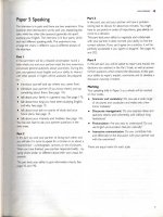
Figure 1.32 Alternative tonnage marks.
Positions and marks,
not drawn to scale
or
1080 mm if timber
loadline assigned
Marks may be white or yellow on a dark background as an
alternative
Diagram showing the relative
position of the alternative
tonnage mark in relation
to the loadline disc.
300 mm
All lines 25 mm thick
Optional tonnage mark
for fresh or tropical
waters
300 mm
TD
190 mm230 mm 190 mm
25 mm
Assigned tonnage
draught (TD)
540mm
1
48
th
‘Computer Software’
Many vessels now employ computer loading
programmes to establish disposition of cargo,
ballast and stores.
Such software can be beneficial in producing
the ships stability data, together with anticipated
stress factors throughout the ships length.
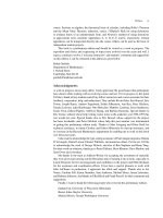
24 Seamanship Techniques
TF
F
T
S
W
W
Starboard side
450 mm
300 mm
540 mm
1
48
th
LD
FWA
V
N
LTF
LF
Assigned
lumber
draught
(LD)
230 mm
25 mm
230 mm
All lines 25 mm
LWN
LS
LT
FWA
LD
LD
Figure 1.33 Timber loadlines.
held to ensure that the conditions of assignment and the loadline marks
remain unchanged.
Should the loadline be submerged through the overloading of the
vessel, so contravening the regulations then the master or owner is liable
to a fine of £1000.00 plus £1000.00 for every cm or part of 1 cm over-
loaded. The upper edge of loadline marks are the recognised mark levels.
The loadline itself (Figure 1.31) is punched into the shell plate and
painted a distinctive colour, usually white or yellow on a dark background.
Owners of vessels may make application to the Maritime and Coastguard
Agency for a vessel to be assigned an alternative tonnage. Gross and
registered tonnages are assigned not only for the upper deck but also for
the second deck, excluding the ’tween deck space, so treating the second
deck as the upper deck level.
Once an alternative tonnage has been assigned the tonnage mark
(Figure 1.32) will be carved on each side of the vessel below the second
deck and aft of the loadline disc. Should the vessel be so loaded as to
submerge the alternative tonnage mark, then the normal gross and registered
tonnage will apply. Should the state of loading leave the mark visible,
then the modified tonnage values will remain valid.
1
48
th
1
36
th
LW
2
ANCHOR WORK
With the many different types of vessel employed in the marine industry,
it is only to be expected that anchors and their associated equipment
have changed considerably over the years. From the forerunners used by
the ancient Greeks to the present day, purpose and design have been
dictated by the needs of the industry.
ANCHORS
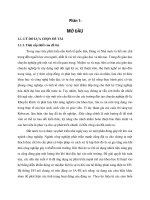
Admiralty Pattern Anchor
Sometimes referred to as a ‘fisherman’s’ anchor, this design is still popular
within the fishing industry (Figure 2.1(a)). It has been in use for many
years, but because it has difficult stowage characteristics, e.g. it cannot be
stowed flat with the stock in position, it has been followed by more
manageable designs. Once let go, the stock, lying at right-angles to the
direction of the arms/flukes, causes a fluke to dig into the sea bed. This
leaves the remaining fluke exposed, and the cable may often foul it when
the vessel swings. When the anchor is not in use, the forelock in the
stock can be unshipped, permitting the stock to be stowed parallel to the
shank.
The holding power of this anchor is generally considered to be very
good indeed. The design is such that the stock is longer and heavier than
the arms. This lends itself to the theory that the stock will be dragged flat
along the sea bed, causing one of the flukes to bury itself. The angle of
the stock would also be expected to turn the flukes in the direction of
the sea bed as the anchor strikes the bottom. It is interesting to note that
the longer the shank on these anchors the better it holds.
The weight of the stock must be equal to 25 per cent of the weight
of the anchor itself. Some stocks are designed straight if the weight of the
anchor is over 12 cwt (610 kg), but a bent stock, as indicated in Figure
2.1(a) would be encountered on anchors below this weight.
The holding power of this common anchor will be, roughly speaking,
three to four times its weight, depending on the nature of the sea
Shank
Gravity band
Forelock
Stock
Fluke
Arm
Crown
Pea or
bill
(a)
Shank
Hollow fluke
Knuckle
Hinge pin
Stops
(b)
Figure 2.1 Admiralty pattern anchor (above) and (below)
Admiralty cast anchor type 14 (AC14).
26 Seamanship Techniques
Shank
Stock
bottom. It is unlikely to be seen on board merchant vessels, except
possibly as a lifeboat anchor or as a kedge anchor. The weight in any
event would rarely exceed two tonnes.
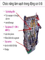
The Stockless Anchor
This is by far the most popular anchor in general use today its principal
parts are shown in Figure 2.2. The head of the anchor is secured to the
shank by a hinged bolt which allows the arms to form an angle of up to
45° with the shank. Further rotation of the arms are prevented by the
head meeting the shank, at the built-in stops. The head of the anchor is
comprised of the flukes, the arms, and the crown which are manufactured
from cast steel, whereas the shank is made of cast steel or forged iron.
The hinge bolt and the shackle are made of forged iron. The stockless
anchor’s greatest advantage is its close stowing properties and is easily
housed in the hawse pipe when not in use. It is easily handled for all
anchor operations, and made anchor beds (used with the close stowing
anchor) obsolete.
The overall size of these anchors will vary between individual ship’s
needs but the head must be at least three-fifths of the total weight of the
anchor. Holding power again varies depending on the nature of the
bottom but, as a rule of thumb, it may be considered to be up to three
times its own weight. The mariner should be aware that the rotation
action of the moving arm may cause the anchor to become choked
when on the sea bed so that the arms/flukes are not angled to the full
amount and therefore losing the holding power effect.
Admiralty Cast Anchor
Used extensively as a bower anchor for warships, this anchor, because of
good holding properties, is becoming very popular with the merchant
service (Figure 2.1(b)). With the increase in size of ships – the large
tankers of today, for example – shipowners required an anchor with
greater holding power. The AC Type 14, as it was called, was developed
in the United Kingdom and has the required properties. Tests showed
that it had more than twice the holding power of a conventional stockless
anchor of the same weight. With such an obvious advantage, Lloyds
Classification Society granted a 25 per cent reduction in regulation
weight. The holding properties of this anchor are directly related to the
fluke area, the angle of which operates up to 35° to the shank. The angle
of the flukes is made possible by a similar operation as with the stockless
anchor, in which a hinge pin passes through the shank in the crown of
the anchor.
CQR
Illustrated in Figure 2.3, the CQR sometimes referred to as a ‘Plough-
share’ anchor or, in the United States, just as a plough anchor. It is
generally used as a mooring anchor, especially for the smaller type of
vessel. Holding power is again dependent on the type of ground that the
Head of the anchor
Fluke
Arm
Anchor crown
shackle
Shank
Tripping
palm
Pea or bill
Crown
Figure 2.2 Hall stockless anchor.
Figure 2.3 CQR anchor (above), Danforth anchor (below).
27Anchor Work
anchor is bedding into but has been found to be very good. It also has
extremely good resistance to drag. Like the Admiralty Pattern, it is
difficult to stow. The design has been modified since its invention to
incorporate a stock, and is often used as a mooring anchor (Figure
2.28(b)). The CQR was a British invention by scientist Sir Geoffrey
Taylor, who was a man with little boating experience. The invention
showed that the application of basic principles can sometimes improve
on practical experience. Small-boat owners tend to have the choice of
two anchors on the market, namely the Danforth and the CQR. Both
anchors have reasonable holding power but the Danforth may have a
tendency to drag whereas the CQR will not.
For easier handling and stowing the Danforth would be more popular,
but if it is decided to use an anchor for the job it was meant for,
preference is generally given to the CQR.
Danforth Anchor
Generally accepted as a small-boat anchor, this anchor dominates the
American boat market (Figure 2.3). A stock passes through the head of
the anchor, allowing it to be stowed easily in a similar manner to the
stockless anchor. Holding power is about 14.2 times its own weight. The
anchor is of American design, and the idea of the stock being passed
through the crown of the anchor as opposed to the top of the shank
demonstrates a practical solution to the stowage problem. The stock in
this position prevents the anchor being fouled on its own cable. Holding
properties are good but not as good as the CQR’s, and it has a tendency
to drag or glide until the flukes bite into the sea bed. The action of this
anchor is similar to that of the stockless anchor, where the tripping palms
catch and cause the flukes to be angled to the shank. With the Danforth
anchor, the tripping palms are generally situated closer to the centre line
of the anchor. Once tripped, the spade-shaped flukes will tend to dig
into the bottom.
TESTS ON ANCHORS
All anchors over 168 lb (76 kg) in weight must be tested and issued with
a test certificate. The weight of any anchor for the purpose of the rules
and regulations governing anchors and cables shall:
(a) for stockless anchors include the weight of the anchor together with
its shackle if any, and
(b) for stocked anchors, the weight of the anchor including its shackle,
if any, but excluding the stock.
Drop Test (cast anchors)
Any part of an anchor over 15 cwt is subjected to a percussion test by
being dropped both end on and side on from a height of 12 ft on to an
iron or steel slab. After that, the piece must be slung and hammered all
over by a 7 lb sledgehammer. A clear ring must be produced to show that
no flaw has developed during the percussion test.
28 Seamanship Techniques
TABLE 2.1 Proof loads for anchors
Weight Proof Weight Proof Weight Proof Weight Proof Weight Proof Weight Proof
of load of load of load of load of load of load
anchor anchor anchor anchor anchor anchor
——— ——— ——— ——— ——— ——— ——— ——— ——— ——— ——— ———
Kg Tonne Kg Tonne Kg Tonne Kg Tonne Kg Tonne Kg Tonne
——— ——— ——— ——— ——— ——— ——— ——— ——— ——— ——— ———
76 3.33 700 15.20 2300 39.60 4700 65.10 7200 82.60 15000 117.70
——— ——— ——— ——— ——— ——— ——— ——— ——— ——— ——— ———
80 3.46 750 16.10 2400 40.90 4800 65.80 7400 83.80 15500 119.50
——— ——— ——— ——— ——— ——— ——— ——— ——— ——— ——— ———
90 3.70 800 16.90 2500 42.20 4900 66.60 7600 85.00 16000 120.90
——— ——— ——— ——— ——— ——— ——— ——— ——— ——— ——— ———
100 3.99 850 17.80 2600 43.50 5000 67.40 7800 86.10 16500 122.20
——— ——— ——— ——— ——— ——— ——— ——— ——— ——— ——— ———
120 4.52 900 18.60 2700 44.70 5100 68.20 8000 87.00 17000 123.50
——— ——— ——— ——— ——— ——— ——— ——— ——— ——— ——— ———
140 5.00 950 19.50 2800 45.90 5200 69.00 8200 88.10 17500 124.70
——— ——— ——— ——— ——— ——— ——— ——— ——— ——— ——— ———
160 5.43 1000 20.30 2900 47.10 5300 69.80 8400 89.20 18000 125.90
——— ——— ——— ——— ——— ——— ——— ——— ——— ——— ——— ———
180 5.85 1050 21.20 3000 48.30 5400 70.50 8600 90.30 18500 127.00
——— ——— ——— ——— ——— ——— ——— ——— ——— ——— ——— ———
200 6.25 1100 22.00 3100 49.40 5500 71.30 8800 91.40 19000 128.00
——— ——— ——— ——— ——— ——— ——— ——— ——— ——— ——— ———
225 6.71 1150 22.80 3200 50.50 5600 72.00 9000 92.40 19500 129.00
——— ——— ——— ——— ——— ——— ——— ——— ——— ——— ——— ———
250 7.18 1200 23.60 3300 51.60 5700 72.70 9200 93.40 20000 130.00
——— ——— ——— ——— ——— ——— ——— ——— ——— ——— ——— ———
275 7.64 1250 24.40 3400 52.70 5800 73.50 9400 94.40 21000 131.00
——— ——— ——— ——— ——— ——— ——— ——— ——— ——— ——— ———
300 8.11 1300 25.20 3500 53.80 5900 74.20 9600 95.30 22000 132.00
——— ——— ——— ——— ——— ——— ——— ——— ——— ——— ——— ———
325 8.58 1350 26.00 3600 54.80 6000 74.90 9800 96.20 23000 133.00
——— ——— ——— ——— ——— ——— ——— ——— ——— ——— ——— ———
350 9.05 1400 26.70 3700 55.80 6100 75.50 10000 97.10 24000 134.00
——— ——— ——— ——— ——— ——— ——— ——— ——— ——— ——— ———
375 9.52 1450 27.50 3800 56.80 6200 76.20 10500 99.30 25000 135.00
——— ——— ——— ——— ——— ——— ——— ——— ——— ——— ——— ———
400 9.98 1500 28.30 3900 57.80 6300 76.90 11000 101.50 26000 136.00
——— ——— ——— ——— ——— ——— ——— ——— ——— ——— ——— ———
425 10.50 1600 29.80 4000 58.80 6400 77.50 11500 103.60 27000 137.00
——— ——— ——— ——— ——— ——— ——— ——— ——— ——— ——— ———
450 10.90 1700 31.30 4100 59.80 6500 78.20 12000 105.70 28000 138.00
——— ——— ——— ——— ——— ——— ——— ——— ——— ——— ——— ———
475 11.40 1800 32.70 4200 60.70 6600 78.80 12500 107.80 29000 139.00
——— ——— ——— ——— ——— ——— ——— ——— ——— ——— ——— ———
500 11.80 1900 34.20 4300 61.60 6700 79.40 13000 109.90 30000 140.00
——— ——— ——— ——— ——— ——— ——— ——— ——— ——— ——— ———
550 12.70 2000 35.60 4400 62.50 6800 80.10 13500 111.90 31000 141.00
——— ——— ——— ——— ——— ——— ——— ——— ——— ——— ——— ———
600 13.50 2100 36.90 4500 63.40 6900 80.70 14000 113.90
——— ——— ——— ——— ——— ——— ——— ——— ——— ———
650 14.30 2200 38.30 4600 64.30 7000 81.30 14500 115.90
Proof loads for intermediate weights shall be obtained by linear interpolation.
29Anchor Work
The Bending Test (cast anchors)
An additional piece of metal, 20 cm long, is cast with the piece to be
tested, and is cut away for the purpose of the bending test. This piece will
be turned down to 2.5 cm in diameter, and bent cold by hammering
through an angle of 90° over a radius of 3.75 cm. The casting will be
deemed sufficiently ductile if no fracture appears in the metal.
All anchors are subject to the proof strain (Table 2.1), and subsequent
proof load, but only cast steel anchors will be subjected to percussion,
hammering, and bending tests. Wrought iron, or forged steel anchors are
not subjected to these tests as they are forged from red hot slab by
hammering. All other anchors will also be annealed.
MARKS ON ANCHORS
Each anchor must carry on the crown and on the shank the maker’s
name or initials, its progressive number, and its weight. The anchor will
also bear the number of the certificate, together with letters indicating
the certifying authority (Figure 2.4).
ANCHOR CERTIFICATE
After the test on the anchor is completed, an anchor certificate will be
awarded. The certificate will show the following:
Type of anchor.
Weight (excluding stock) in kilogrammes.
Weight of stock in kilogrammes.
Length of shank in millimetres.
Length of arm in millimetres.
Diameter of trend in millimetres.
Proof load applied in tonnes.
Identification of proving house, official mark and government mark.
Number of test certificate.
Number of tensile test machine.
Year of licence.
Weight of the head of the anchor.
Number and date of drop test.
CHAIN CABLE TESTS
Anchor cable over 12.5 mm in diameter is accepted for testing at an
approved testing establishment in lengths of 27.5 m. (1 shackle of cable).
The manufacturer will provide three additional links for the purpose of
the test. These three links will be subjected to a tensile breaking stress,
and if this proves to be satisfactory, then the total length of the cable will
be subjected to a tensile proof test, the tests being carried out on approved
testing machines. If two successive links break, the cable is rejected.
Before the test on chain cable is carried out, the supervisor will satisfy
Figure 2.4 Marks on cable. X (certificate Number);
YYY (certifying Authority).
X
Y Y Y
30 Seamanship Techniques
himself that the quality of the material from which the cable is manufactured
meets with the requirements of the anchor and chain cable regulations.
After a successful test on chain cable a certificate is awarded, stating:
Type of cable.
Grade of cable.
Diameter in millimetres.
Total length in metres.
Total weight in kilogrammes.
Length of link in millimetres.
Breadth of link in millimetres.
Tensile breaking load applied in tonnes.
Tensile proof load applied in tonnes.
Number and types of accessories included.
The certificate issued shall also show:
A serial number.
Name of the certifying authority.
Mark of the certifying authority.
Name of the testing establishment.
Mark of the testing establishment, if any.
Name of the supervisor of tests.
The certificate is signed on behalf of the certifying authority.
NOTES ON CABLE
Accessories
Anchor shackles, and joining shackles are all ordered together with any
additional fittings for the size of cable they are intended to work and be
associated with. These accessories must be subjected to similar tensile
load and proof load tests as the cable.
Material of Manufacture
Wrought iron, forged mild steel, cast steel, or special quality forged steel
are used. Wrought iron is weaker than the other three materials, and is
expensive to produce; consequently it is rarely seen on present-day
merchant ships. Types of cable are shown in Tables 2.2 and 2.3.
Size of Cable
The size is measured by the diameter of the bar from which the link is
manfactured. Aboard a vessel the size could be obtained from the chain
cable certificate, or callipers could be used to measure the actual cable.
KENTER LUGLESS JOINING SHACKLE
The Kenter Lugless Joining Shackle, manufactured in nickel steel, is the
most popular method of joining shackle lengths of the anchor cable
together. The shackle has four main parts, as shown in Figure 2.5. The
31Anchor Work
TABLE 2.2 Types of chain cable
27.5 m = 15 fathoms = 1 shackle length
Grade Meterial Method of manufacture Tensile range
kg/mm
2
1a Wrought iron Fire welded 31–41
1b Mild steel Fire welded 31–41
1c Mild steel Flash butt welded 31–41
1d Mild steel Flash butt welded 41–50
2a Steel Flash butt welded
or drop forged 50–65
2b Steel Cast 50 min
3a Steel Flash butt welded
or drop forged 70 min
3b Steel Cast 70 min
TABLE 2.3 Stud link chain cable
Diam. I (U1) II (U2) III (U3) Minimum weight
mm Proof Break Proof Break Proof Break per shackle
length
12.5 4.7 6.7 6.7 9.4 9.4 13.5 0.105
50.0 70 100 100 140 140 200 1.445
60.0 98.8 141 141 198 198 282 2.075
70 132 188 188 263 263 376 2.85
90 209 298 298 417 417 596 4.705
122 357 510 510 714 714 1019 8.55
152 515 736 736 1030 1030 1471 13.20
Figure 2.5 Kenter lugless joining shackle.
Shackle broken
Dovetail recess chamber
Stud
Lead pellet
Shackle assembled
two main halves interlock with the stud forming the middle of the link.
All parts are held together with a tapered spile pin. This spile pin is made
of steel and is driven into the shackle on the diagonal. A lead pellet is
then forced into the inverted dovetail recess to prevent the pin from
accidentally falling from the shackle.
The manufacture of the shackle in nickel steel prevents corrosion and
the parts becoming frozen together. It allows the shackle to be ‘broken’
with relative ease when either the cable is to be end-for-ended or
shackles are to be tested. When breaking the shackle, remove the spile
pin by using a punch and drift (Figure 2.15). If the lead pellet has not
been prised out first, be careful that it is not forced out by the percussion
effect of the drift driving the spile pin, for it may emerge with considerable
force. A back stop should be provided to prevent persons being injured
by the lead pellet being expelled from the recess.
Once the spile pin is removed, the stud can be extracted; the two
halves of the shackle can then be separated by means of a top swage
obtained from the manufacturer. When the shackle is reassembled, care
must be taken to ream out the dovetail recess, so that no residual lead is
left inside. Should this not be done, then the next lead pellet inserted will
not spread out and obtain a grip inside the recess.
The construction of the Kenter shackle is such that it is larger than
Spile pin
32 Seamanship Techniques
the common links but not by so much that it will not fit into the snug
of the gypsy of the windlass or cable holder. However, care should be
taken that it does not lie flat on the gypsy and cause jamming.
The main advantage of this type of joining shackle is that open end
links are not required, as with the ‘D’ lugged joining shackle. In addition,
all shackle lengths are the same, which ensures smoother working in the
snugs of the gypsy. The shape of the Kenter lends itself to cable working,
especially around and over the bow, and the tendency for it to catch is
comparatively rare. As with other accessories, these shackles are tested,
but because of their type of manufacture in nickel steel, they are not
heat-treated.
‘D’ LUGGED JOINING SHACKLE
The ‘D’ lugged joining shackle is used extensively for joining the cable
to the anchor in more modern vessels. In the past this type of shackle
was used, as the Kenter lugless joining shackle is used today, in the
joining of the shackle lengths of cable together. If it is to be used for this
purpose, the rounded crown part of the shackle should always face
forward, so that it does not foul the anchor when letting go.
It should be noted that the anchor crown shackle and the ‘D’ joining
shackle face the opposite way to all other ‘D’ joining shackles in the
cable. The mariner should be aware that the anchor, together with the
initial joining shackle, is walked out of the hawse pipe prior to letting go
(except in some cases of emergency). Consequently, the anchor crown
shackle would not foul, but should other joining shackles be facing in
this manner, there would be a distinct possibility of the lugs of the
shackle catching on a snag in the letting-go operation.
When using these types of shackle between cable length, each cable
length must have an open link at the ends. This is necessary to allow the
passage of the lugs through the cable.
The construction of the ‘D’ lugged joining shackle is illustrated in
Figure 2.6, where it may be seen that the bolt, generally oval in shape, is
passed through the lugs and across the jaw of the shackle. A tapered spile
pin of steel, brass or wood holds the bolt in position, a lead pellet being
hammered home into a dovetail recess chamber to keep the spile pin
from accidently being expelled. The spile pin should be tapered to a ratio
of 1:16, and wooden pins are made of ash or solid bamboo. When
breaking the ‘D’ joining shackle, the bolt will be hammered from the
unlipped end, causing the wooden spile pin to shear.
Should the spile pin be made of steel, then this must be expelled by
using a punch and drift in a similar manner to that described for the
Kenter shackle. The steel pin is generally found in the ‘D’ shackle joining
the anchor cable to the anchor. When assembling these shackles, it is
customary to give the bolt a smear of tallow to allow easy ‘breaking’ at
a later date. Should the shackle become jammed and difficult to break,
then it can be heated about the lugs. This will cause the lugs to expand,
allowing the withdrawal of the bolt.
Figure 2.6 ‘D’ lugged joining shackle.
Crown
Clear
Lead pellet
Tapered
spile pin
Bolt
Dovetail
chamber
Jaw
Lug
33Anchor Work
SECURING AND STOWAGE OF ANCHORS
Alternative methods of securing anchor to cable are illustrated in Figure
2.7, and the operation of the cable in anchoring in Figure 2.8. There are
many different designs of hawse pipe (Figure 2.9) in commercial use
with the modern merchant vessel and the warship. The general arrangement
is such that the axis of the pipe does not exceed 45° from the vertical;
however, the most suitable angle is that which allows the easy lowering
and restowing of the anchor. Many hawse pipe arrangements are recessed
into the shell plate. This not only reduces drag effect, especially on high
speed vessels, but should contact with another vessel or quay occur,
damage is considerably reduced.
Many of the modern anchors, e.g. AC14 and Bruce (see Figure 2.27),
have incorporated an anchor bed or special stowage frame fitment about
the entrance to the pipe. This usually facilitates smoother operation
when letting go and better securing for the anchors when not in use.
SECURING ANCHOR AND CABLE
Securing the bitter end of the anchor cable is illustrated in Figures 2.10
and 2.11, the fo’c’sle head in Figure 2.13 and anchor securing in Figure
2.13. Figure 2.15 lists chain cable accessories.
Open end link
Enlarged link
Two (or more)
link attachment
‘D’ type
end shackle
Alternative 2
Open end
link
Enlarged
link
Common
link
Three link adapter
piece
Anchor
Anchor crown
shackle
Alternative 3
Anchor shackle swivel
Enlarged
link
Kenter
shackle
Anchor
Anchor
Alternative 1
Anchor crown
shackle
Kenter
shackle
Common
link
Kenter
shackle
Figure 2.7 Securing anchor to cable.
Cable drum
gypsy
Windlass
Cable
Brake
Compressor or bow stopper
Deck plating
Hawse pipe
To anchor
on the
sea bed
Warping drum
Devil’s claw
Windlass
bed
Spurling pipe
Stores
Hatch
To remainder of cable
Cable locker
Forepeak of vessel
Figure 2.8 Operation of cable in anchoring.
NB. The devils claw shown in Figure 2.8 is shown for
display purpose and would not normally be secured when
the anchor is deployed.
Deck plate
Doubler
Underdeck frames
Hawse pipe (tubular
steel)
Bolster (steel)
‘D’
‘D’ represents the diameter of the
hawse pipe and is at least nine
times the chain diameter.
Shell plate
Figure 2.9 Arrangement of hawse pipe.
34 Seamanship Techniques
STEAM WINDLASS OPERATION
The following is a typical list of checks to be carried out before a steam
windlass can be operated safely. You should consider what modifications
to the list are needed to operate the type of windlass on your current
vessel if it is different.
1. Inform the engine room of the requirement for steam to operate
the windlass.
2. On the way to the windlass, ensure that the main deck steam-line
valve is open (this may in fact be in the engine room), and drain
deck line.
3. Check that the windlass stop-valve is open (usually found under
the bed of the windlass inside the forecastle head), and ensure any
lashings in the chain locker are removed.
4. Open the drain cocks of the cylindrical steam chests (normally
two cocks per chest).
5. Ensure that the windlass operating valve is closed (stop–start control).
6. Wait until pure steam issues from the drain cocks – not a mixture
of steam and water.
7. Close the drain cocks, and steam is now at the windlass head ready
for use.
8. Ensure that the brake is firmly applied and that the windlass is out
of gear.
9. Turn the windlass over by operating the start–stop valve.
10. Oil ‘moving parts’ as necessary to facilitate smooth running (obviously
oil is applied to a stationary windlass for safety reasons).
Windlasses, winches and capstans are illustrated in Plates 4–8.
PREPARING ANCHOR FOR ‘LETTING GO’
Once power has been obtained on deck, and the windlass has been oiled
and checked, the anchors must be made ready to ‘let go’. This operation
must be carried out carefully and systematically to ensure that the ‘letting
go’ operation will run smoothly. If a proper routine is established when
time is not limited, the anchoring procedure is more likely to go smoothly
and quickly when an emergency occurs.
Once deck power is obtained, the following operations are carried out:
1. Check that the windlass brake is on and holding and that the
windlass is in gear.
2. Remove the hawse pipe covers.
3. Remove the devil’s claw.
4. Remove any additional lashings.
5. Remove the bow stopper, guillotine or compressor.
6. Take off the brake and walk the cable back a short distance in
order to break the cement pudding inside the spurling pipe.
Modern ships often have spurling pipe covers instead of cement
seals. If fitted these should be removed.
7. Clear away old cement and throw overside.
Bulkhead
Bulkhead stiffening
PORT
Split pin to prevent accidental
removal of retaining pin
Open link
Anchor cable
Anchor cable retaining pin– this pin will be
removed in an emergency. If the pin is
removed while there is tension on the anchor
cable, the operation will be difficult and
DANGEROUS.
Plan view
STARBOARD
Figure 2.11 Alternative method of securing bitter end.
An external fitment is situated outside
and usually above the chain locker. The
hinge cover when in position prevents
removal of the locking pin holding the bitter
end of the cable. This method allows the
cable to be slipped without any person being
ordered into the locker. The locking pin is
removed by a simple sliding motion once
the hinged cover has been lifted. The cable
is then released and the bitter end is allowed
to fall back into the locker.
Figure 2.10 Internal securing of bitter end of anchor
cable by Use of clench system inside cable locker.
In some cases the link may pass through
the bulkhead, the pin being placed on the
other side. It is not then necessary for a
man to enter the chain locker at all in
order to slip cable.
Watertight hinged cover
Holding bar
or locking pin
Open link
Chain cable
Brake handle
Pay out direction
Band brake
Floating link
Brake tension applied
Floating end of
brake band
Anchored end of
brake band
Securing pins
Figure 2.12 Windlass band brake system.
35Anchor Work
8. Walk back on the cable until the anchor is out, clear of the hawse
pipe and above the water surface, then heave a few links back to
ensure cable will run.
9. Screw the brake on hard and check that the brake is holding.
10. Take the windlass out of gear, leaving the anchor holding on the
brake. Check that it is out of gear by turning power on briefly.
Report to the Bridge that the anchor is on the brake and ready for
letting go.
CABLE HOLDERS
Cable holders (Figure 2.16) are often fitted to large merchant vessels as
an alternative to the windlass, and, with recent developments, may be
seen on passenger vessels. They have also been popular with warships for
some considerable time because they are compact and lie low on the
deck.
Early models employed a cable drum (gypsy) without the valuable
addition of warping facilities. Modern versions include a warping drum
geared to the centre-line axle. This can subsequently be de-clutched
when working anchor cables. A separate braking system is incorporated
in each cable holder, similar to that fitted to the windlass.
Anchor securing arrangements are similar, except that the bow stopper
is usually situated closer to the hawse pipe than to the cable holder. A
devil’s claw or slipping arrangement is sited between the bow stopper
and the holder.
Where cable holders are used, the lead of cable is always close to the
deck. To prevent excessive wear to deck plating from cable friction, a
‘Scotsman’ is a common fixture to provide the required protection.
Variations of combined capstan/cable holders are available on the
commercial market, powered by steam or, more commonly, electricity.
Roller type
fairleads
Hawse pipes
(with cover plates)
(Additional wire or
chain lashings to
anchor cable)
Compressor
(Guillotine bar)
bow stopper
Bitts
Windlass
Devil’s
claw
Warping
drum
Windlass brake
Spurling pipes
Cable
Figure 2.13 Fo’c’sle head anchor and cable arrangement
(plan view).
4. Hydraulic windlass before being fitted, showing
warping drums, gear plates, gypsy and exposed snug
to accommodate anchor cable, band brakes and brake
control wheels. Manufactured by Robertson’s of
Fleetwood.
36 Seamanship Techniques
As with other similar deck machinery, additional strengthening of deck
areas about operational sites is required to accommodate excessive load.
PROCEDURE FOR COMING TO ANCHOR
The preliminaries to the operation include careful scrutiny of the chart
of the area where the vessel is proposing to anchor, and consideration of
the depth of water and the holding ground with the view to determining
the amount of cable to use (Figure 2.17). The amount will be determined
by the following:
1. Depth of water.
5. Pneumatic windlass showing band brake controls
exposed and anchor cable passing over gypsy and
entering spurling pipes.
6. Single barrel hydraulic mooring winch, with 5 tonne
to 40 tonne pull at design speed of 15 to 10 revolutions
per minute, depending on size and weight of material
being heaved.
37Anchor Work
7. Double barrel anchor-handling/towing winch of a
type extensively fitted in offshore supply vessels.
Designs include a four-speed range and automatic
fail-safe hydraulic braking systems.
8. Hydraulic capstans before being fitted, showing
underdeck motor, single drum and vertical capstan.
(a)
Lever
(b)
Bracing claw
(Optional)
Roller
Cable
Figure 2.14 (a) Self-holding and automatically
releasing roller bowstopper,
manufactured and produced by
Clark Chapman Ltd. (b) Self-
holding and automatically
releasing track bowstopper.
38 Seamanship Techniques
Cable
Bottle screw
DEVIL’S CLAW
ANCHOR LASHING
Bottle screw
Shackle
Approx.
1m
Cable jack
Chain hook
Drift for
inserting pins
Drift for
expelling pins
Figure 2.15 Chain cable accessories.
Figure 2.17 Amount of cable to use when anchoring.
Vessel
Water surface
Hawse pipe
Anchor
cable
(minimum length ‘4D’)
Scope of cable
Depth of water
‘D’
Anchor
Sea bed
2. Type of holding ground, good or bad.
3. Length of time the vessel intends to stay at anchor.
4. Sea room available for circle of swing.
5. Expected weather conditions.
6. Strength of tide, if any.
7. Draught and amount of hull exposed to the wind.
8. Type of anchor and its holding power.
These factors will vary with each case and previous experience; however,
as a general rule, four times the depth of water may be taken as a
working minimum. This would change, say, if the holding ground was
bad, the weather deteriorating, and you were expected to remain at
anchor for a long period of time.
The Anchor Plan
An anchor plan should be established between the interested parties,
namely: The Ships Master/Captain or Offshore Installation Manager
(OIM), the Officer in Charge (OiC) of the anchor party, or the Master
of Anchor Handling Vessel (AHV). It would be expected that these key
personnel would inform relevant crew members through an established
chain of command, regarding relevant criteria.
In the construction of any anchor plan the following items must be
worthy of consideration:
1. The intended position of anchoring of the vessel.
2. The available swinging room at the intended position.
3. The depth of water at the position, at both High and Low water
times.
4. That the defined position is clear of through traffic.
Warping drum
Chain reliever
Snug
Scotsman
Cable holder
Brake
Deck level
Spurling pipe
Underdeck strength
girders
Hawse pipe
Figure 2.16 Cable holders.
39Anchor Work
5. That a reasonable degree of shelter is provided at the intended
position.
6. The holding ground for the anchor is good and will not lend to
‘dragging’.
7. The position as charted is free of any underwater obstructions.
8. The greatest rate of current in the intended area of the anchorage.
9. The arrival draught of the vessel in comparison with the lowest
depth to ensure adequate under keel clearance.
10. The choice of anchor(s) to be used.
11. Whether to go to ‘single anchor’ or an alternative mooring.
12. The position of the anchor at point of release.
13. The amount of cable to pay out (scope based on several variables).
14. The ship’s course of approach towards the anchorage position.
15. The ship’s speed of approach towards the anchorage position.
16. Defined positions of stopping engines, and operating astern
propulsion (single Anchor Operation).
17. Position monitoring systems confirmed.
18. State of tide ebb/flood determined for the time of anchoring.
19. Weather forecast obtained prior to closing the anchorage.
20. Time to engage manual steering established.
When anchoring the vessel it would be usual practice to have com-
munications by way of anchor signals prepared for day and/or night
scenarios. Port & Harbour Authorities may also have to be kept informed
if the anchorage is inside harbour limits or inside national waters.
NB. Masters or Officers in Charge, should consider that taking the vessel into an
anchorage must be considered a Bridge Team operation.
Single Anchor – Procedure
The master, or pilot, should manoeuvre the vessel to the desired position,
and take all way off, so that the vessel is stopped over the ground. She
should be head to the wind and/or tide, and have her anchor walked
back out of the hawse pipe, on the brake ready for letting go. The Bridge
should be informed that the anchor is on the brake of the windlass, or
cable holder, and is ready for the order to ‘let go’.
The engines should be operated to give stern way to the vessel. The
Master should check overside and see the stern wake, about half-way up
the vessel’s length, and know that stern way is being made through the
water, before giving the order to ‘let go’. The officer in charge of the
anchor party should order the brake to be taken off and allow the cable
to run out with the weight of the anchor. The idea is to lay the cable out
in length along the sea bottom, and not cause it to pile up on itself.
The officer in charge should start to apply the brake once enough
cable has run out to prevent it falling on top of the anchor. The procedure
is to check on the cable periodically, by applying the brake, while the
vessel drops astern, either under engine power or through the action of
the tide, and lays the required length of cable.
Communication from the fo’c’sle head to the Bridge should be
40 Seamanship Techniques
maintained by walkie-talkie, loud hailer/phone, or by the ringing of the
ship’s forward bell.
Bell Signals
When heaving in the cable or letting go, the bell should be struck once
for every shackle’s length, e.g. three shackles, three strokes of the bell.
When the anchor breaks clear and becomes ‘anchor aweigh’, then a
rapid ringing of the bell will indicate to the Bridge that the anchor is
aweigh. Prudent Chief Officers tend not to ring anchor aweigh until the
anchor is sighted and the flukes clear the water, in case the anchor has
become fouled in any way with, say, warps or power cables.
Marking of Anchor Cable
As the anchor is let go, the officer in charge of the anchor party will
require to know the amount of cable being paid out. Each shackle length
will be identified by the joining shackle, which is a larger link than the
other links of the cable. The individual shackles will be distinguished by
the number of studded links either side of the joining shackle. In the
example given in Figure 2.18 the fourth shackle is used, and the fourth
studded link from the joining shackle will be bound around the stud
with seizing wire. This identification by means of seizing wire will be
seen to mark the fourth shackle on both sides of the joining shackle.
Seizing wire is used to enable the officer in charge to feel about the stud
of the link and so locate, by his sense of touch, how far away the marked
link is from the joining shackle – very useful during the hours of
darkness. Seizing wire is used because it is quite robust and will stand a
fair amount of wear and tear when the anchor is being let go, whereas
the paint mark (see below) may tend to chip, or flake off, after a short
period of time.
The length of cable between the seizing wire portions is painted a
bright distinctive colour, e.g. white, so that each shackle length may
easily be located and acknowledged when operating anchors during the
hours of darkness. Some ships often paint the joining shackle a different
colour to highlight the position of the joining shackle.
If a ‘D’ lugged joining shackle is used to join cable lengths together
(Figure 2.18(b)), then open links are found either side of the ‘D’ shackle.
These open links must not be counted in the marking of the cable with
seizing wire. Only studded links away from the joining shackle are to be
counted.
Anchor cables should be checked whenever an opportunity presents
itself, as in dry dock where the cables can be ranged along the bottom
of the dock and inspected with ease.
CLEARING AWAY ANCHORS
The term ‘clearing away’ means preparing the anchor to let go, though
different ships have different ways of operating. Most vessels are now
equipped with hawse-pipe covers – sliding metal covers which must be
Figure 2.18 Marking anchor cable: (a) fourth shackle
of cable; (b) second shackle length by means
of ‘D’ lugged joining shackle. Open links
on either side of the joining shackle are
ignored for the purpose of marking cable
in this case.
(a)
Kenter lugless
joining shackle
Seizing wire
1234
432 1
Seizing wire
(b)
Open link
Open link
‘D’ lugged
joining shackle
Seizing wire
Common
link
41Anchor Work
removed in order for the cable to run clear. Anchor lashings may be
attached to the bow stopper claw or secured from deck lugs through the
cable itself. These must be released and cleared away, as with the devil’s
claw, if fitted. The compressor or guillotine bar should be removed from
the cable, together with any lashings which may have been applied inside
the cable locker.
Past and Present Practice
A lashing in the cable locker served to stop the cables banging together
when the ship was at sea. In bygone days the sailors used to sleep in the
fo’c’sle head area, and the banging cables tended to keep them awake.
Hence they were lashed secure.
The more up-to-date thinking is that if the cable is lashed the chance
of a bight of cable being buried by the remainder of the pile of cable in
the locker will be reduced. This was especially so in the early days of
non-self-stowing cable lockers.
Another reason, which is now by far the most popular, is that when
the spurling pipes are sealed with cement, this cement plug and seal
would be prevented from cracking up, when the vessel was in a seaway,
by the secure lashing of the two cables together inside the cable locker.
Mariners should be aware that the practice of lashing cables in the
locker is no longer common practice on modern vessels.
Spurling pipes must be sealed, but hinged slide design steel plates are
now by far the most popular method of making them watertight. Should
these steel plates not be fitted, then a pudding plug, made up of rags or
cotton waste, should be forced into the aperture of the spurling pipe.
Cement mix, of four of sand to one of cement, should be poured over
the pudding, about the anchor cable. This cement cover should be of
such thickness that any movement of the anchor cable in the spurling
pipe would not cause the cement to break. The purpose of the pudding
is to stop the cement from dropping through to the cable locker, and also
to give it something to set on.
ANCHOR TERMINOLOGY
Anchor A-Cockbill
When the anchor is hanging vertically from the hawse pipe, with the
flukes turned into the ship’s side (Plate 9). In this position it will not
stow correctly in the hawse pipe.
Anchor Aweigh
The anchor is said to be ‘A-Weigh’ at the moment it is broken out of the
ground and clear of the sea bed.
Anchor Buoy
A buoy used to indicate the position of the ship’s anchor when on the
bottom.
9. Anchor a-cockbill.
42 Seamanship Techniques
Anchor Coming Home
When the anchor is being drawn towards the ship in the operation of
heaving away, by means of the windlass or cable holder/capstan, the
anchor is said to be coming home. Instead of the ship being drawn
towards the anchor, the reverse is happening.
Anchor Dragging
The anchor is said to be dragging when it is not held in the sea bed. It
is said to bite well when it has a good hold in the ground. The vessel is
‘dragging her anchor’ if she moves her position while dragging the
anchor over the sea bed.
Anchor Warp
The name given to a hawser or rope when it is attached to the anchor
and used as a temporary cable.
Brought Up
A vessel is said to be brought up when her way has stopped and she is
riding to her anchor, with the anchor holding. The terms ‘come to’ and
‘got her cable’ are sometimes used to mean the same thing. The officer
in charge of an anchor party will know when the vessel is brought up,
by the cable rising up from the surface towards the hawse pipe when the
brake is holding it. The vessel should then move towards the anchor,
causing the cable to drop back and make a catenary (Figure 2.19).
Cable Clench
A strong steel forged fitting in the cable locker for securing the ‘bitter
end’ of the cable (see securing of anchors, p. 33).
Cable Jack
A device for lifting the cable clear of the deck (see anchor accessories,
p. 38).
Cable’s Length
A length of 600 ft, or 100 fathoms (183 m).
Cat the Anchor
The anchor is said to be catted when hung off, from what used to be
called the clump cathead. More modern vessels will be fitted with a pipe
lead set back from the line of the hawse pipe and used for the purpose
of ‘hanging off an anchor’. Found in practice when mooring to buoys by
means of mooring shackles with the cable.
Chain Hook
A long iron hook used for the manhandling of cable links (see chain
cable accessories, p. 38).
Line of cable as vessel is
brought up
Catenary of cable as vessel
draws back towards the holding anchor
Figure 2.19 A vessel brought up.
43Anchor Work
Cross
Occurs when the cables are fouled as in foul hawse, when the ship has
swung through 180° a cross being formed with the two cables (see
Figure 2.20).
Drop an Anchor Under Foot
Letting an anchor go to the bottom, then holding on to the brake. This
is sometimes done to steady the ship’s head and prevent her yawing
about when lying to a single anchor. Care must be taken in this operation
that the second anchor is let go when the riding cable is growing (see
below) right ahead, and not when it leads off the bow.
Elbow
Occurs when the cables are fouled as in ‘foul hawse’. When the ship has
swung through 360°, an elbow is formed in the anchor cables (see
Figure 2.20).
Foul Anchor
The term used to describe the anchor when it has become caught on an
underwater obstruction. The flukes of the anchor often become fouled
by an old hawser or cable, obstructing its normal use.
Foul Hawse
This term is used to describe the crossing of the anchor cables, when
both cables are being used at the same time, as with a running, standing
or open moor, owing to the uncontrolled swinging of the vessel when
anchored with both anchors (moored).
Grow
The cable is said to grow when the exposed part of the chain above the
surface, is seen to expand towards the anchor.
Gypsy
The vertical wheel on the windlass which the cable passes over. The
cable is held in the segments of the wheel known as the ‘snug’. The gypsy
is held by the clutch plate (when in gear) or by the brake (when about
to be let go).
Hawse Pipes
The two pipes on either bow which accommodate the bow anchors.
Some vessels may be equipped with a stern anchor. The term hawse pipe
is in general use for the stowage space for the anchors of a vessel.
Hove in Sight
When the anchor is hove home, it is ‘sighted and clear’ at the point when
the anchor crown shackle breaks the surface of the water. A prudent
THE ELBOW
(vessel has swung through 360°)
THE CROSS (vessel has swung through 180°)
Figure 2.20 Clearing foul hawse.
THE ELBOW and CROSS
(vessel has swung
through 540°)
A further turn would result in a round
turn –when the vessel has swung
through 720°
44 Seamanship Techniques
officer would not consider that the anchor is clear until he sees that the
flukes are clear. On the same basis an officer in charge of an anchor party
tends not to ring anchor aweigh until he sees the anchor is hove in sight
and clear.
Joggle Shackle
May be described as a long bent shackle, used for hauling cable round
the bow (Figure 2.21). Sometimes encountered when clearing a foul
hawse or other similar operation in moving of cable.
Kedging
Moving a vessel by means of small anchors and anchor warps.
Long Stay
The term applicable when the cable is leading down to the water close to
the horizontal, with weight on it. A good length of the cable is exposed.
Moored
A vessel is said to be moored when she has two anchors down to the sea
bed.
Ream a Shackle
To clean away any residual lead left inside the lug of a shackle after the
lead pellet and spile pin have been removed, by use of a reaming tool.
Render Cable
To apply the brake lightly so that when weight comes on the cable it will
run out slowly.
Round Turn
Occurs when the cables are fouled as in ‘foul hawse’, when the ship has
swung through 720° or twice round.
Scope
Is the name given to the amount of anchor cable payed out from the
hawse pipe to the anchor crown ‘D’ shackle.
Shackle of Cable
The length of a shackle of cable is 15 fathoms (90 ft). It is defined by the
length of cable between the joining shackles (previously a length of
12
1
2
fathoms).
Sheer
When applied to a vessel at anchor, sheer is an angular movement of the
vessel about the hawse pipe point, it can be deliberately caused by
applied helm to port or starboard.
Figure 2.21 Joggle shackle.
45Anchor Work
Sheet Anchor
An additional anchor carried by larger vessels, a practice largely discontinued
(not to be confused with the spare anchor carried by the majority of
vessels).
Shorten Cable
To heave in a portion of the cable, so reducing the scope.
Short Stay
The cable is said to be at short stay when the anchor is hove in close to
the ship’s side and not over-extended. The cable is not up and down in
this position.
Snub
To snub the cable is to stop the cable running out by applying the brake.
A vessel is said to snub round on her anchor when she checks the paying
out of the cable by applying the brake on the windlass, so causing the
cable to act as a spring, turning the bow smartly in the direction of the
cable.
Spurling Pipes
Termed ‘navel pipes’ in the Royal Navy, the cable passes through these
pipes from the windlass or cable holder to the cable locker.
Surge
To allow the cable or hawser to run out under its own weight. The term
is often used when handling mooring ropes on drum ends. (You should
not surge on man-made fibre ropes, because of the possibility of heat/
friction causing the yarns/strands to fuse.)
Tide Rode
A vessel is said to be tide rode when she is riding at anchor head to tide.
Up and Down
The cable is said to be up and down when the angle the cable makes
with the water surface is 90°, usually just before anchor aweigh.
Veer Cable
To pay out cable under power, by walking back the gypsy of the windlass.
Walk Back the Anchor
To lower the anchor under power.
Wind Rode
A vessel is said to be wind rode when she is riding at anchor head to
wind.
46 Seamanship Techniques
Yaw
A vessel is said to ‘yaw’ when at anchor when she moves to port and
starboard of the anchor position under the influence of wind and/or
tide. Yawing should not be confused with sheering.
WATCH AT ANCHOR
Before the vessel is brought to an anchorage, the Master and engine-
room staff should be informed of the estimated time of arrival (ETA),
and time of anchoring. An anchor approach plan should be prepared, and
speed reduced in plenty of time to assess the approach features and the
anchorage area, including depths for echo-sounder. A responsible officer
should be fully informed of details regarding amount of cable, depth of
water and holding ground, and brief the anchor party accordingly. Power
on deck should be obtained in ample time and the anchor walked back
before the approach is started. Anchor signals or lights, which should
have been tested prior to use, should be made ready.
The state of weather, with particular attention to wind, should be
kept under continual observation. State of visibility, traffic density, and
the proximity to navigation hazards should be assessed before entering
the area for anchoring. Avilability of sea room, especially to leeward,
should be considered before letting go. The state of tide and current,
times of high and low water, and time limits of the vessel when swinging
should all be studied.
Officer of the Watch
The officer of the anchor watch should have all relevant information
regarding the amount of cable paid out, and the estimated position of the
anchor. (An anchor buoy often indicates the approximate area of the
anchor position, but is only a guide.)
The officer’s duties include the checking at regular intervals of the
ship’s position. This may be carried out by observing compass bearings
of fixed objects ashore or prominent landmarks. These bearings laid on
the chart define the vessel’s position. Similar checks may be made by
using radar, the bearing cursor, and the variable range marker. However,
the mariner should not rely solely on radar in case of instrument
malfunction. Transit bearings give a good indication, but the objects used
should be spread well apart so that any movement of the vessel would
open up the transit objects quickly and allow detection of the vessel’s
change in position. The purpose of checking the anchor bearings is to
ascertain the ship’s position, to ensure that she is not dragging her
anchor, so moving her position over the ground.
There are other methods of detecting whether the vessel is dragging.
For example, secure a hand lead overside from the bridge wing, and let
the lead sit on the bottom; if the vessel is dragging her anchor, the lead
line will start to lead forward. This would indicate to the observer that
the vessel was dropping away from the lead sitting on the bottom.
47Anchor Work
Transit Bearings
Extensive, practical use of transit bearings should be made by the officer
of the watch, when the vessel is at anchor, especially when ‘beam transits’
can be obtained. This is not to say that watch officers should rely solely
on good transit marks. They should always employ whatever means at
their disposal to ascertain the ship’s position, checking and double-
checking at regular intervals.
General Precautions
The officer of the watch should also ensure that a deck watch is kept
when the vessel is at anchor. Detection of the vessel dragging may be
ascertained by personnel engaged on this duty ‘feeling the cable’. If the
vessel is dragging her anchor then vibration from the anchor bouncing
over the sea bottom will travel up the length of the cable, especially if the
sea bottom is of a hard, uneven nature.
The deck watch should also be aware that unauthorised personnel
may try to board the vessel in certain regions of the world. Theft and
piracy are rife today in some underdeveloped countries. Access is often
gained by climbing the anchor cable, or by grapple over the stern.
The officer of the watch should ensure that all anchor signals are
displayed correctly, and, if oil lights are used, that these remain alight
throughout the hours of darkness. Deck lights should be used whenever
a vessel is at anchor, together with overside lights.
Correct fog signals should be sounded if the visibility closes in. Radars
should be operational if necessary and a sharp lookout kept at all times.
VHF radio should be on, and a listening watch continually kept on the
local port channel or channel 16.
If in any doubt, the Master should be informed at the earliest possible
moment. Should the vessel drag her anchor, the Master must be informed
immediately. The engine room should be kept ready for immediate
notice in order to manoeuvre the vessel out of any difficulty, should the
need arise. A constant check on weather conditions should be kept, and
all changes and incidents noted in the log book.
When handing over the watch to another officer, the officer of the
watch should inform the relieving officer of all relevant details regarding
the anchor and cable, weather reports, anchor bearings, ship’s position,
depth (from echo-sounder). State of tide, time of expected swing, and
expected circle of swing should all be marked on the chart.
Another Vessel Dragging Towards Your Ship
The options open to the mariner are somewhat limited. A junior officer
faced with the situation should inform the Master immediately. Sub-
sequent actions include drawing the attention of the other vessel to the
fact that she is dragging her anchor, in case the incident is undetected,
make ready own engines, and send forward an anchor party.
Drawing Attention to the Situation
When vessels are in sight of one another (Rule 34(d) of The Regulations