Seamanship Techniques 2011 E Part 4 pdf
Bạn đang xem bản rút gọn của tài liệu. Xem và tải ngay bản đầy đủ của tài liệu tại đây (2.09 MB, 40 trang )
103Wirework and Rigging
Gyn Tackle
This purchase (Figure 4.29) comprises a double and treble block, with a
cordage or wire fall rove between them. The standing part is secured to
the double block. The tackle produces a power gain of 6 or 5, depending
on whether it is used to advantage or disadvantage.
Three-fold Purchase
A heavy duty tackle comprising two triple sheave blocks with a rope or
wire fall rove between both blocks, this purchase is used extensively in
heavy lift work for both topping lift and lifting purchase (see Figure
4.30).
There are two methods of reeving the three-fold purchase, one with
the sheaves of both blocks in the same plane and the second, more
popular, method with the plane of the sheaves in each block at right-
angles to each other. The advantage of the latter, is that when the lift is
made, the lower block hangs vertically without toppling over to one
side.
Chain Blocks
There are several types of chain block in general use, the most common
being (a) spur geared blocks, (b) lever and ratchet, and (c) wormwheel
operation. They are often referred to as chain hoists, having a mechanical
advantage of between 5 and 250. The lifting capability will be variable
but their use for up to 40 tonnes is not uncommon practice. Although
they are usually found operating from inside the machinery spaces of
vessels, for numerous duties they may be employed on deck.
Figure 4.27 Luff tackle. Figure 4.28 Double luff tackle. Figure 4.30 Three-fold purchase.Figure 4.29 Gyn tackle.
104 Seamanship Techniques
With spur geared blocks a manual drive chain turns a through spindle
via geared cog wheels. A ratchet and pawl system is also incorporated so
that the load may be held suspended from the load chain. This load chain
is held by a sprocket arrangement which is being driven by the operation
of the through spindle.
The lever and ratchet types, generally used for lighter work, are
smaller and permit optional positioning wherever it is required. They are
usually equipped with a reversible pawl system which allows its ratchet
wheel to be turned in operation in either direction.
Wormwheel
Load sprocket
Driving
sprocket
Worm
Load chain
Operating hand chain
Ratchet wheel
Hard steel ball
Cap
Driving sprocket
Brake disc
Hoist
Load chain
Thrust collar
Friction washer
Figure 4.31 Chain block.
105Wirework and Rigging
In wormwheel operation (Figure 4.31) an endless operating chain
passes over a flywheel that causes an axle fitted with a worm screw to
rotate. The worm screw engages with the helical teeth of a larger gear
wheel, causing the load sprocket to turn and heave on the load chain.
The load chain may be led through a floating block to increase the
purchase effect of the machine or, as in Figure 4.31, be led direct from
the load sprocket to the lifting hook. Nearly all these types of chain
block incorporate a braking system that allows the weight being lifted to
be suspended.
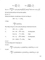
Weston’s Differential Purchase
Let us find the mechanical advantage (see Figure 4.32).
Consider a load, W, being raised by the effort P.
Each of the chains A and B support
1
2
W (
1
2
weight)
Take moments about centre C. Let radii of large sheave be represented
by R and small sheave by r.
Then
1
2
W × CD = (P × CF) + (
1
2
W × CE)
By transposition of the above equation
P × CF = (
1
2
W × CD) – (
1
2
W × CE)
Substitute radii R and r
PR =
1
2
W(CD – CE)
PR =
1
2
W(R – r)
Transpose
1
2
W =
PR
(R – )r
1
2
W
P
=
R
(R – )r
W
P
=
2R
(R – )r
But
W
P
=
Load
Effort
= Mechanical advantage (MA)
∴
MA =
2R
(R – )r
Instead of radii R and r being used, the number of links which can be
fitted round the circumference of the upper block sheaves may be
substituted, as they are in proportion to the radii of the sheaves.
Upper block
F
r
C
R
D
1
/
2
W
1
/
2
W
P
Endless
chain
B
A
Lower
block
Load = W
E
Figure 4.32 Weston’s differential purchase. The upper
block consists of two sheaves of different
diameters, secured together. An endless chain
(right) is rove between the upper and lower
blocks. The links of the chain engage in
the snug and under the rims of the sheaves,
and cannot slip, so eliminating any frictional
losses.
5
LIFTING GEAR
DERRICKS
The most widely used derricks in the marine industry are of a welded
structure, consisting of either three or five welded sections of tubular
steel. Wooden derricks, which generally lifted only up to 3 tonnes, have
largely been superseded.
At the heel of the derrick (Figure 5.1) either a single flange or a
double flange will be welded to permit attachment to the gooseneck, a
through bolt passing between the gooseneck arrangement and the flange(s)
of the derrick. This bolt, once secured, is guarded by a washer and split
pin holding, or, in the case of heavy lift derricks, by shallow nut and split
pin. The bolt is not subjected to lateral forces and the split-pin securing
is generally an adequate method of retaining the bolt in position.
At the head of the derrick a spider band is fitted to permit the
attachment of guys, topping lift and lifting purchase. This band is forged
in one piece, the lugs not being allowed to be electrically welded to the
band. Some heavy lift derricks have the spider band manufactured so
that the lugs opposite each other are attached to a yoke piece that passes
through the derrick, providing additional strength in working.
It is often the case when a derrick has a fairly considerable length, say
12 m or more, that derrick guides are fitted to prevent the cargo runner
from sagging. These guides may take the form of a fixed hoop welded to
the derrick, or they may be provided with a cast-iron roller. These rollers
should be regularly maintained or they may cause undue chafe on the
cargo runner wire.
Derrick gear is illustrated in Plate 11.
Single Swinging Derrick
The function of the derrick is to raise, transfer and lower weights. In the
shipping industry this effectively means moving goods from the quay to
the vessel or vice-versa.
The derrick boom is supported at the heel in a pivot arrangement
0.36L min.
Convex
taper
Straight
taper
Spider
band
Flange
Length L
Figure 5.1 Derrick arrangement.
107Lifting Gear
known as the gooseneck, which allows elevation by means of a topping
lift span. The topping lift may be of the nature of a single span or a
purchase; either way the downhaul is led from the spider band of the
derrick via the masthead span block (high upper support) to a convenient
winch. Figure 5.2 shows a single span secured to a union plate, which
also accommodates a chain preventer and a bull-rope. The bull-rope is a
continuation of the downhaul for the purpose of topping or lowering
the derrick.
The derrick is positioned to plumb the load by slewing the boom
from port to starboard by means of a slewing guy secured on either side
of the spider band. Slewing guys come in two parts, namely a cordage
tackle (wire in the case of heavy lift derricks) secured to a wire guy
pendant which is shackled at the derrick head.
The derrick may be equipped with a lifting purchase or a whip
(single) cargo runner. In either case, once the derrick has been plumbed
at the correct height for the load, the topping lift is secured, and the
downhaul of the lifting purchase is led to the winch via the derrick heel
block.
Many vessels are provided with dolly winches for the sole purpose of
topping and lowering derricks. Dolly winches are usually fitted with a
safety bar device and leave the main cargo winch to handle the lifting
purchase or runner. Other types of dolly winch are operated from the
main winch, in which case combined use of topping lift and lifting
purchase is not possible, the dolly winch having to be disengaged to
allow separate operations to be carried out.
When the derrick is rigged in the single swinging mode, the topping
lift is secured and the actual height of the derrick does not change.
However, the bull-rope may be replaced by a luff tackle, with the
consequence that the topping lift effectively becomes the downhaul of
11. Gooseneck and derrick heel block arrangement.
Samson post
Tumbler
Topping lift
Span
Guy
Runner
Cargo hook
Guy
Spider band
Monkey face-plate
(or union plate)
Bull-rope
Chain
preventer
Heel block
Snatch block
Gooseneck
Lift link when
attaching shackle
Ring-bolt in deck
Figure 5.2 Single swinging derrick – single span topping
lift chain preventer.
Head block
Preventer guy
108 Seamanship Techniques
the luff tackle. If this is led to the winch direct, then the derrick is turned
into a luffing derrick. With this method of rigging a second winch will
be required to operate the cargo runner.
Topping a Single Span (Topping Lift) Derrick
1. Assume the derrick to be in the lowered position, secured in the
crutch. Collect the chain preventer from its stored position, together
with two tested shackles, a snatch block, seizing wire, marline
spike and wire preventer if the derrick is to be rigged for union
purchase.
2. Obtain power on deck and remove the cargo runner from the
main barrel of the winch.
3. Secure the slewing guys to the spider band and stretch them to
port and starboard.
4. Shackle the cargo working end of the runner to the deck, so as not
to end up with the eye of the runner at the derrick head when
topped.
5. Secure the bull-wire to the winch barrel (assuming no dolly winch
system) via the snatch block.
6. Let go the derrick head lashing or crutch clamp, and man the
guys.
7. Lift the derrick clear of the crutch (float the derrick) and pass the
wire preventer over the derrick head, if for use with union purchase.
8. Heave on the winch, topping the derrick until the union plate
(monkey face-plate) is down to the snatch block.
9. Shackle the chain preventer on to the union plate, mousing the
shackle.
10. Come back on the winch, lowering the derrick to the required
height. Secure the chain preventer when the derrick reaches the
desired working height. When shackling the chain preventer to the
deck lug bolt, ensure that the shackle is clear of the next link of the
preventer, so as not to foul and cause the rig to jump when under
load. Mouse the shackle.
11. Remove the bull-rope from the winch and secure hand tight
about the mast cleats. This bull-rope will now provide a back-up
to the chain preventer.
12. Secure guys once the derrick is slewed to the desired position.
13. Secure the cargo runner once more to the main barrel of the winch.
Topping a Derrick – Topping Lift Span Tackle
1. Assume the derrick (Figure 5.3) to be in the lowered position,
secured in the crutch. Obtain lead block, chain stopper, marline
spike, rope yarns and wire preventer guy if the derrick is to be used
in union purchase rig.
2. Obtain power on deck and remove the cargo runner from the
barrel of winch.
3. Secure slewing guys to the spider band and stretch them to port
and starboard.
Figure 5.3 Single swinging derrick – topping lift span
tackle.
Tumbler
Mast head span block
Topping lift
span tackle
Derrick head span block
Preventer guy (attached
to outboard side)
Upper cargo
purchase block
Guy pendant
Lower cargo
purchase block
Spider band
Slewing
guy block
Derrick heel
lead block
Gooseneck
Span lead
block
Chain stopper
ÒPreventer guy only rigged when the derrick
is to be worked in union purchaseÓ
109Lifting Gear
4. Shackle the cargo working end of the runner to the deck, so as not
to end up with the eye of the runner at the derrick head when
topped.
5. Take the weight of the topping lift downhaul by passing a chain
stopper round it. Lead the downhaul of the topping lift via a lead
block on to the main barrel of the winch. Take the weight of the
wire on the winch and remove the chain stopper.
6. Remove the derrick head lashing or crutch clamp, and man the
guys.
7. Lift the derrick clear of the crutch and pass the wire preventer
over the derrick head for use with union purchase.
8. Top the derrick up to the desired working height, by heaving on
the topping lift downhaul.
9. Pass the chain stopper on the topping lift downhaul once the
derrick is at the required working height and the winch is stopped.
10. Ease back on the winch until the weight comes on to the chain
stopper.
11. Remove the topping lift downhaul from the winch and secure it
12. Two 10-tonne derricks rigged in union purchase
employing a schooner guy between the spider bands,
and topped together.
110 Seamanship Techniques
hand tight about the mast cleats. This operation should be carried
out while the weight is on the chain stopper. Once completed, the
stopper can be removed. When turning the wire up on to the mast
cleats, make three complete turns before adding the four cross
turns, the whole being secured with a light rope yarn lashing.
12. Provided a lead block is used for the downhaul of the topping lift,
and not a snatch block, there is not the need to remove the block
from the way of the wire.
13. Secure slewing guys once the derrick is plumbed correctly, and
also the cargo runner to main barrel of winch.
UNION PURCHASE
This is by far the most popular rig using two derricks (see Plate 12). It
is a fast efficient method of loading or discharging cargo. The derrick
may be used in a single swinging mode when not employed in a union
purchase rig, so providing versatile cargo handling over a considerable
range of cargo weights.
The rigging of the union purchase rig (Figure 5.4) is arranged by
plumbing the inshore derrick over the quayside, while the second derrick
is plumbed over the hatch area containing the cargo. The two cargo
runners are joined together at a triple swivel hook, known as a union
hook, or often referred to as a Seattle hook (Figure 5.5). The two
derricks are held in position by slewing guys, which, once the derricks
are plumbed correctly, are secured, so that the derricks will not be
allowed to move. The operation is carried out by the weight of the load
being taken by one derrick and transferred via the cargo runners to the
second derrick (Figure 5.5). It should be noted that the derricks do not
move throughout the whole operation. The only moving parts are the
two cargo runners led to winches.
The stresses that come into play when working this rig are considerable
because of the angles made with the cargo runners, and as a rough guide
one-third of the safe working load of the derricks may be taken as a
working weight, e.g. 5 tonnes SWL of derricks, then 1.6 tonnes may be
considered the SWL of the union purchase rig.
Union purchase rig has several variations, the main one being in the
distribution and position of guys (Figures 5.4 and 5.5). An advantage
with the schooner guy is that there is a saving of cordage, as only three
guys are used to secure the rig, while with crossed inboard guys the total
is four slewing guys.
When rigging derricks for union purchase rig, each derrick should
be topped in the normal manner (see p. 108). The exception to this is
when the schooner guy is fitted: then both derricks should be topped
together, with the tension being kept on the schooner guy to prevent
them splaying apart as they rise. For the operation of topping derricks
with the schooner guy, more manpower is obviously required to top
both derricks at once.
Preventer guys, not to be confused with slewing guys, should be
Samson post
Span wire
Spider band
Schooner
guy
Derrick
Runner
Hatch
coaming
Guy
Preventer
Figure 5.4 Union purchase rigged with schooner guy.
For clarity, guardrails etc. have been omitted.
Cargo
Treble-swivel
hook
Runner
Preventer
Guy
Span wire
Winch
Samson
post
Deck
Cargo hatch
Hatch
coaming
Schooner
guy
The Seattle (treble-swivel)
hook is used so that no
wire is forced to have
ÔturnsÕ in it.
Figure 5.5 Union purchase rig (plan view).
111Lifting Gear
passed over the derrick heads once the derricks have been floated from
their crutches.
Preventer Guys
Preventer guys are to be fitted in addition to slewing guys, and their safe
working load should not be less than that indicated in Table 5.1 or as
found by parallelogram of forces of the rig, whichever is the greater.
TABLE 5.1 Safe working load
SWL of derrick rig Required SWL of each slewing guy
(tonnes) (tonnes)
11
21
1
/
2
32
42
1
/
2
53
63
1
/
4
7 to 9
1
/
2
3
1
/
2
10 to 12
1
/
2
3
3
/
4
13 to 15 4
16 to 60 25% of SWL of derrick rig
61 to 75 15
more than 75 20% of SWL of derrick rig
The above table may be considered a guide only when vessels are at suitable angles of heel
and trim. Under certain conditions, when additional slewing guys are attached to the lower
cargo purchase block, a permitted reduction in safe working loads of guys is tolerated.
Preventers should be made of wire rope, or wire and chain construction,
and attached to the derrick separately from the slewing guys. Deck eye
plates should be so positioned so as to prevent excessive guy tension
building up, while keeping the working area clear for the passage of
cargo slings. Preventers should be secured by use of shackles through the
chain link to the eye plate on the deck, or if all wire preventers are being
used, then securing is often obtained by ‘ferrules’ fused on to the wire at
regular intervals and held by a pear link arrangement.
The preventer should be rigged with an equal tension to that of the
slewing guys on the outboard side of both derricks. Should the rig
become over-strained in any way, then the slewing guy will be allowed
to stretch, being cordage, whereas the preventer will bear the weight and
not give, being of wire or chain construction. An even tension on preventer
and outboard guy is attained by securing both these guys first, and then
taking the weight on the inboard guy of each derrick in turn.
Slewing Guys
Slewing guys are generally constructed in two parts: a guy pennant of
steel wire rope shackled to a cordage tackle. This provides a limited
112 Seamanship Techniques
amount of elasticity, allowing the guy to stretch and avoid parting under
normal working conditions.
Table 5.1 is a guide to the safe working load of guys in respect of safe
working loads of derrick rigs. When rigging derricks in union purchase,
slewing guys, and preventer guys should never be secured to the same
deck eye bolt but to separate anchor points.
SAFE HANDLING PRACTICE FOR DERRICKS
1. All derrick rigging should be regularly maintained under a planned
maintenance programme, and in any event should be visually checked
for any defect before use.
2. Before a derrick is to be raised, lowered or adjusted with a topping
lift span tackle, the hauling part of the topping lift should be flaked
down the deck clear of the operational area. All persons should be
forewarned of the operation, and to stand clear of the bights of the
wire.
3. When topping lifts are secured to cleats, bitts or stag horns, three
complete turns should be taken before the additional four cross
turns on top. A light lashing should be placed about the whole to
prevent the natural springiness of the wire causing it to jump adrift.
4. When the rig of a derrick is to be changed or altered in any way, as
with doubling up, then the derrick head should be lowered to the
crutch or to deck level in order to carry out alterations safely.
5. When dolly winches fitted with a pawl bar are employed, the pawl
should be lifted to allow the derricks to be lowered. Any seaman
designated to carry out this task should be able to give his full
attention to the job and be ready to release the bar should anything
untoward happen in the course of the operation. Under no circum-
stances should the pawl bar be wedged or lashed back.
6. Winch drivers should take instructions from a single controller, who
should pass orders from a place of safety from which a clear and
complete view of the operation must be available. When derricks
are being raised or lowered, winch drivers should operate winches
at a speed consistent with the safe handling of the guys.
7. Cargo runners should be secured to winch barrels by use of a ‘U’
bolt or proper clamp, and when fully extended, a minimum of three
turns should remain on the barrel of the winch.
8. Should it be necessary to drag heavy cargo from ’tween decks the
runner should be used direct from the heel block via snatch blocks
to avoid placing undue overload on the derrick boom.
Safe Handling Reminders for Union Purchase Rig
1. To avoid excessive tension in the rig the safe working angle between
the married cargo runners should not normally exceed 90°, and an
angle of 120° should never be exceeded.
2. The cargo sling should be kept as short as is practicable to enable
the cargo to clear the hatch coaming without extending the safe
working angle between the cargo runners.
113Lifting Gear
3. Derricks should be topped as high as practicable, and not rigged
farther apart than is absolutely necessary.
4. Derricks should be marked with the safe working load when rigged
for union purchase. Should this not be the case, then the safe working
load should not be more than one-third the SWL of the derrick
itself.
5. Preventer guys of adequate strength should be rigged on the outboard
side of each derrick, and secured to the deck in the same line and
with similar tension as the slewing guy. However, they must be
secured to separate pad eyes to the eyes which accommodate the
slewing guys.
DOUBLING-UP PROCEDURE
The cargo runner of a derrick may be doubled up when it is desired to
make a lift which the rig is capable of handling safely but which exceeds
the SWL of the cargo runner when rigged as a single whip (see Figure 5.6).
Some derricks are equipped with a second doubling-up spider band
but this is not the case with every derrick. Obviously the doubling of the
runner, making a double whip, is made very easy when the second spider
band is fitted. The eye of the runner is shackled to the second band,
leaving a bight between the head block and the shackled eye. A floating
block is secured in the bight, effectively making the arrangement into a
‘gun tackle’.
Should the derrick not have the convenient second spider band, then
it will be necessary to parcel the derrick with canvas and take a half hitch
with the runner around the derrick, taking the eye of the runner and
securing it to the lug on the spider band that accommodates the topping
lift. This effectively produces a similar bight in the wire for the floating
block as previously described.
When doubling up in this manner it will be appreciated that a snatch
block used in the bight would be much simpler to rig, but it would not
be as safe as an ordinary cargo block. This will necessitate the reeving of
the block before completing the half hitch about the derrick.
The half hitch is prevented from riding down the derrick by the
retaining shackle to the spider band and also by the wire biting into the
parcelling that affords the derrick some protection. Once the load is off
the cargo hook, the tension in the half hitch is relieved, but, owing to the
weight of the wire and the floating block, it would be unlikely for the
hitch to slip against the natural forces of gravity.
BUTTERFLY RIG
This rig is very similar to union purchase, except that derricks from
adjacent hatches are used, whereas with the union purchase rig, derricks
from an individual hatch are used. The advantage of this rig is that it
often enables a maximum number of stevedore gangs to be engaged by
combining both butterfly and union purchase rigs throughout the vessel.
As indicated in Figure 5.7, the vessel is loading/discharging into
barges. Table 5.2 shows how this is done.
Doubling up spider
band
Double whip
(effectively making
a gun tackle)
Doubling up by means of
second spider band
Spider
band
Derrick
Parcelling to protect
the derrick
Doubling up when second
spider band is unavailable
Figure 5.6 Doubling up a derrick.
Figure 5.7 Butterfly rig.
Example tonnagesNumber of gangs
2
2
1
1
2
1
2
3
4
5
1200
1300
600
600
1300
114 Seamanship Techniques
The rig can prove useful when the distribution of cargo is such that
all hatches must be kept working so as to complete cargo operations at
approximately the same time. It is not a common method of rigging,
however, and often has the disadvantage that ventilators and masts etc.
impede the area of plumbing the derrick.
YO-YO RIG
This rig is sometimes referred to as a block in bight rig, and may be
employed with two or four derricks. The purpose of the rig is to allow
the loading or discharge of heavier loads than those which can be
handled by the more popular union purchase rig or by a single swinging
derrick.
With Four Derricks
This is probably the most popular of the two yo-yo methods (Figure
5.8). The derricks once rigged for union purchase do not have to be
adjusted. The two cargo runners of the inboard derricks are passed
through a floating block, and the two outboard derrick runners are
passed through a second one. The separate pairs of runners are shackled
together, as are the floating blocks, to form the union, the cargo hook
being secured under the floating blocks.
The lifting operation can be started once the guys have been tightened
up. The winch operators should be warned beforehand that, with the
runners being shackled together, the joining shackles may run foul of the
derrick head block or the floating block in the bight of the runners. An
experienced winchman will identify the limits of the wire runner by
marking the wire to indicate the extent the runner may be paid out or
heaved in without fouling the blocks.
With Two Derricks
This rig uses the two inshore derricks. Each derrick in Figure 5.9 has
been rigged with a gun tackle, and the moving blocks have been joined
by a heavy strop supporting a floating block with cargo hook attached.
The operation of loading or discharge is carried out by slewing both
derricks towards the quayside, trying to keep both the derrick heads as
close together as is practicable.
The advantage of the floating block with the strop is that, should the
TABLE 5.2 Loading and discharging using different rigs
Hatch no. Gangs employed Type of rig
1 2 Butterfly
2 2 Butterfly
3 1 Union purchase
4 1 Union purchase
5 2 Butterfly
Deck
Samson
post
Derrick
Winch
Guy
Hatch
Preventer
Cargo runner
with shackle
Floating
block and
cargo
hook
Figure 5.8 Yo-yo rigged with four derricks.
Figure 5.9 Yo-yo rigged with two derricks.
Topping lift Ð derrick 2Topping lift Ð derrick 1
Derrick 2
Derrick 1
Gun tackle
Strop
Floating block
Hook
Yo-Yo rig with two
derricks
115Lifting Gear
rig suffer a winch failure, the full weight of the load will not come to
bear on one derrick.
HALLEN UNIVERSAL DERRICK
This probably represents one of the most successful advances in lifting
gear over the last twenty years. The many advantages of this type of
derrick make it a very popular choice with the shipowners (see Figure
5.10).
The derrick is labour saving, as it can be operated by one man. The
lifting capacity may be up to 200 tonnes, through a working radius of
170°, being topped up to 85°. It is an extremely stable rig, being supported
by either a straight mast or a ‘Y’ style mast. Stabilising outriggers provide
superior leads for the slewing operation over the greater working area.
These outriggers, a recent innovation, have almost completely superseded
the ‘D’ frame design of the early 1960s.
The complete operation of the derrick rig is handled by one man
positioned at a control console. A joystick control allows topping and
lowering, together with slewing to port and starboard, and a second lever
operates the lifting purchase hoist. The guys of the conventional derrick
design have virtually been eliminated in this design. The topping lifts
have a double function of slewing the derrick as well as controlling the
elevation. The topping lift wires take up to 75 per cent of the load and
so provide greater safety aloft.
The whole design and operation may be compared to that of a crane
inclusive of built-in limit switches that prevent overslew and overtopping.
Variations in the reeving of the topping lifts have occurred since the ‘D’
Outrigger stay
Outrigger
Non-twist
hoist wire
Roller bearing
swivel
Figure 5.10 Hallen universal swinging derrick.
Figure 5.11 Hallen container derrick.
Topping/
slewing
winch
Derrick
control joy stick
Hoist control
Cargo hoist winch
Topping/slewing winch
116 Seamanship Techniques
frame type, the slew tackles having been replaced by an endless fall rove
to function as a conventional topping lift.
HALLEN CONTAINER DERRICK
This container derrick (Figure 5.11) consists of two parallel derricks
connected by a top beam that is flexible to the derricks themselves. This
beam is always perpendicular to the line of the derricks, allowing the
container cargo to be held and transported from the quay in a maintained
position, irrespective of the derrick positions. The beam supports two
cargo tackles, which may in turn support an automatic grabbing
arrangement for containers.
Should the derrick be required for loading light or heavy general
cargo, then the cargo tackles may be replaced by single cargo runners.
The rig may also be employed as a single swinging derrick using a single
runner rove through a single sheave block secured to the centre of the
top beam.
The container derrick is operated in a similar manner to that of the
Hallen universal derrick, in that one man controls the operation. It has
good stability, operating over 180° radius, and being topped up to
approximately 85°.
Mast
Hoist
winch
Slew winch
Derrick
Topping winch
Hoist wire
Yoke
Figure 5.12 Velle shipshape crane.
117Lifting Gear
VELLE SHIPSHAPE CRANE
This is a derrick system (Figure 5.12) which has become increasingly
popular over the last decade. The boom is fitted with a ‘T’ shaped yoke
at its extremity for the purpose of fitting four short steel wire ‘hangers’.
This bridle arrangement allows very wide slewing angles because the
topping lift falls act to aid recovery when the derrick is slewed outboard.
The yoke also provides the securing points for the two hoist wire leading
blocks. The separation between the leading blocks allows a sympathetic
motion between the load on the hook and the derrick head and so
reduces pendulous swinging of the load.
Luffing and slewing motions of the rig are controlled by two winches
each equipped with divided barrels. The luffing winch accommodates
the fall wires, being turned up on to the barrels in the same direction, so
allowing both to lengthen or shorten as desired, while the wires on the
slewing winch are turned up in opposite directions. As rotation occurs
one fall shortens while the other pays out, so slewing the derrick to port
or starboard.
13. Velle crane in operation.
118 Seamanship Techniques
The advantages of this type of rig are that cargo-handling speed can
be increased, since the derrick can engage in luffing and slewing operations
at the same time while under full load. It has also been shown to be a
very stable rig in operation, being controlled by a single operator using
a joystick lever control similar to the Hallen derrick.
HEAVY LIFT PROCEDURES
Before beginning a heavy lift operation the officer in charge should
make sure that the lift can be carried out in a safe and successful manner.
Depending on the load to be lifted, the vessel can be expected to heel
over once the lift moves off the fore and aft line. Therefore, heads of
departments should be given ample warning of an expected list, before
the operation begins.
The ship’s gangway should be lifted clear of the quayside, and all fore
and aft moorings tended, to ensure no damage is incurred by the heeling
angle of the vessel. The critical times are when the load is overside and
the vessel is at maximum angle of heel, and once the load is landed and
the vessel returns to the upright position.
The vessel’s stability should be thoroughly checked before starting
the operation, with particular regard to free surface in tanks. When the
lift is taken up the derrick, the rise in the ship’s centre of gravity should
be such that she is not rendered unstable. (The effective C of G of the
load acts from the derrick head position above the centre of gravity of
the ship once the load is lifted.)
All rigging must be examined by the officer in charge, and any
preventer backstays to the supporting mast structure should be secured
in position prior to lifting the load. Correct slings should be used on the
load, together with beam spreaders if required. Steadying lines should be
secured to all four corners of the load, and these should be substantial
enough to control oscillations when lifting from ship to quay and vice-
versa.
Steam guys or power guys should be rigged and tested to ensure
correct leads. The lifting purchase should be seen to be overhauling, and
winches should all be in double gear.
The lugs on the load itself should be checked before securing slings
to ensure that they are adequate to handle the load stress. Extreme care
should be taken with crated heavy objects. Shippers are known to crate
loads without reinforcing the crate itself, and the possibility of having
the load fall from the bottom of the crate is a real one.
Landing the load on to a truck or flat top rail car may cause lateral
drag on the vehicle as the weight comes off the derrick; and the vessel
may return sharply to the upright position, accentuating this effect. To
alleviate the situation, the offshore guy could be eased out as the load
lands and the lifting purchase should be veered smartly. It is essential that
competent winch drivers are operating the lifting purchase and the guys,
and that throughout the operation they are under the control of a single
person.
A heavy lift derrick is shown in Plate 14.
119Lifting Gear
Rigging of a Heavy Lift (Jumbo) Derrick
This operation is generally carried out with the derrick (Figure 5.13) in
the vertical position while clamped against the mast. Special lugs are
secured to the mast to facilitate the raising of the topping lift blocks to
the required positions. The topping lift is often left in the reeved condition,
in place between the derrick and the mast, and in this case the rigging
is usually protected by a canvas covering.
Rigging should proceed as follows:
1. Check that the vessel is in the upright position on an even keel.
2. Clear away any other rigging, such as smaller derricks or radio
aerials, which may be in the way of operation.
3. Clear away any canvas protective covers.
4. Rig preventer backstays to the mast if required.
5. Ensure the topping lift is in good condition, securely shackled in
position.
14. Heavy lift derrick shown in the stowed (vertical)
position, with supporting samson post (goalpost)
arrangement accommodating smaller derricks for
general purpose cargo operations.
120 Seamanship Techniques
6. Engage two winches for the port and starboard power guys (steam
guys). Check that the leads from the winches to the derrick head
are clear of all bad nips and that the moving blocks will not foul
deck equipment.
7. Engage two other winches, one for the lifting purchase, the other
for the topping lift. Many vessels remove the lifting purchase after
use; if this is the case, then the derrick will have to be lowered to
just above hatch level to allow the head block to be secured and
the reeving of the tackle to take place.
8. Send a man aloft to pass a wire messenger about the derrick head
and to remove the clamp holding the derrick to the mast.
9. Once the clamp has been removed, the weight should be taken on
the messenger to break out the derrick. The derrick should be
lowered to a point where the lifting purchase can be conveniently
secured. As the derrick is broken out and in the process of being
lowered, the topping lift should be seen to be overhauling.
10. Check that all winches are in double gear and that all rigging is
secure before commencing the lift.
The time for rigging the derrick will vary with the experience of crew
members, but one to two hours should be allowed for. The movements
of the derrick under load are by necessity slow, to reduce stress. When
operating, due regard should be taken of the weight of the slings, which
may be in excess of 3 tonnes.
Precautions
1. Ensure that the stability of the vessel is adequate and the maximum
heel acceptable. Remove free surfaces where practicable by ‘pressing
up’ or emptying tanks (large GM – small heel). (GM stands for
Initial transverse metacentric height.)
2. Rig extra mast stays as necessary.
3. Carefully check condition of derrick and gear before use. Ensure
free rotation of sheaves. Oil and grease as necessary. Ensure SWL
of all gear is adequate and that appropriate valid test certificates are
in Register of ships lifting appliances and cargo handling gear.
(When checking SWL, allow for weight of purchase and other
lifting gear.) After breaking out derrick, check for free rotation and
slewing about gooseneck.
4. Rig fenders as necessary.
5. Ensure all moorings are taut and have men standing by to tend as
necessary.
6. Put winches in double gear.
7. Clear area of deck where weight is to be landed of all obstructions
and lay heavy dunnage (bearers) to spread load. Secure or jam
bearers in position.
8. Check ship’s data to ensure deck is strong enough to support load.
If in doubt, shore up from ’tween deck.
9. Clear area of all but essential personnel.
10. Ensure winch drivers are competent and fully aware of who is to
give directions.
Masthead topping lift
span block
Forward
masthouse
Trunnion
Lifting
purchase winch
Heavy lift derrick
Port steam guy
Topping
lift winch
Starboard
steam guy
Area of load passing
overside
Lead block
(at deck
level)
Starboard
guy winch
Port
guy winch
Lead
block
Figure 5.13 Heavy lift jumbo derrick (plan view).
121Lifting Gear
11. Secure steadying lines to corners of load.
12. Remove rails if possible.
13. Cast off any barges alongside.
14. Before lift begins inform all relevant personnel, e.g. engineers,
cooks and stevedores working other holds.
15. Raise gangway before lift commences.
16. Use lifting points – otherwise sling it, using dunnage for sharp
corners. If possible, use long strops to avoid them pulling together.
17. Set tight steam guys before lifting (set about 30° to horizontal,
making a good angle with derrick head). Consider attaching guys
to floating block.
18. When all is ready, take weight slowly then stop and inspect all
round before lifting further. If all is in order proceed with caution.
Stulcken Derrick
This is a heavy lift rig (Figures 5.14 to 5.16) fitted to well over 200
merchant vessels. There are several variations but the design is largely
one of a heavy derrick supported by two inclined masts (inclined in the
outboard direction). It is operated by four winches, two of which work
the topping lift falls. The main advantages of the rig are its great lifting
capacity (up to 320 tonnes SWL), its fast cargo handling, and its ability
to operate at two separate hatches.
The rig is equipped with over 100 anti-friction bearings, which
produce only about 2 per cent friction throughout a lifting operation.
These bearings do not require maintenance for up to four years, and,
with the fact that deck gear is reduced with this rig, the reduced
maintenance programme becomes a welcome relief to ships’ operators.
Design features include the four heavy duty winches, arranged in
pairs inside the supporting mast posts. The winches, one above the other,
have two gear ratios, which allow operation of half load at twice the full
load hook speed. Safety switches are incorporated with each winch to
prevent any irregularities when lifting, the topping and slewing of the
derrick being handled by one pair of winches while the other pair
operate the cargo lifting purchases.
The standard wire for the rig will be 40 mm, and the barrels of
the winches are generally spiral grooved to safeguard the wire ropes for
the first layer of turns. The length of span tackle will be a variable on the
length of the derrick and the radius of operation.
CRANES
The crane, although a standard piece of port or harbour equipment, has
been incorporated aboard the modern cargo vessel with successful results.
Not only is the crane a labour-saving device (only one driver per crane)
but the manoeuvrability of the cargo hoist is much greater than that of
a derrick (see Plate 15).
Most shipboard cranes may be fitted to swing through 360° but, for
the purpose of safe handling, limit switches often act as cut-outs to stop
the jib of the crane fouling obstructions. Limit switches are also fitted to
Derrick
Tabernacle
Roller
bearing
Figure 5.14 Stulcken derrick. The heel is set on a
tabernacle that has a roller bearing for
derrick movement.
122 Seamanship Techniques
Figure 5.16 Stulcken mast – pivot type.
Capacity SWL 250 tons.
Length of derrick 30 m.
Outreach up to 14.15 m.
Operation with up to 5° list and/or –2° trim.
Double pendulum type
capacity SWL 300 tons.
Split purchase type
capacity SWL 105 tons.
Figure 5.15 Stulcken masts, for heavy lifting operations.
Both types are manufactured by Blohm and Voss. Each
system may be fitted with mast cranes or light derricks
for the handling of smaller cargo.
123Lifting Gear
the luffing operation of the jib, as well as the cargo hoist wire, to prevent
offsetting of the jib-boom, and the cargo hook fouling the upper sheave(s)
of the hoist.
All cranes are provided with individual motors to permit luffing,
slewing and cargo hoist operation. They can operate against an adverse
list of approximately 5° together with a trim of 2°. Twin cranes may
operate independently or be synchronised to work under one driver
from a master cabin.
The seafarer should be aware that there are many types of crane on
the commercial market and their designs vary with customer requirements.
As a general rule cranes conform to the following design:
Machinery platform. Accommodates the DC generator; gearboxes for luff,
slew and hoist operations; the slewing ring; and the jib foot pins.
Driver’s cabin. Integral with the crane structure. Welded steel construction
with perspex windows. Front windows to open. Internal lighting.
15. Deck crane with safe working load of 10 tonnes.
124 Seamanship Techniques
Jib. Of welded steel construction. Supporting upper sheaves for topping
lift and cargo hoist.
Sheaves. Mounted in friction-resistant bearings.
Topping lift and hoist. Galvanised steel wire ropes having a minimum
breaking strain of 180 kgf/mm
2
. Depending on the SWL of the crane,
this breaking strain could be greatly increased.
CRANES AND DERRICKS – ADVANTAGES AND DISADVANTAGES
Cranes. Advantages in use are:
1. Ability to plumb over the lifting point.
2. Single-man operation, controlling luffing, slewing and hoisting.
3. Straight lift means that SWL is usually adequate.
Disadvantages in use are:
1. Complexity of operation requires lengthy maintenance.
2. SWL decreases with jib radius, because the span becomes less effective
as it approaches the horizontal.
3. Large amount of deck space required for installation.
Derricks. Advantages in use are:
1. Simplicity of component parts.
2. Ability to change rig to suit loading/discharging requirements.
3. Maintenance is minimal, provided that winches are good.
Disadvantages in use are:
1. Deck is cluttered with guyropes and preventers.
2. Operation usually requires two winch drivers and a hatchman.
3. Time delays in changing derrick rig for different cargoes.
Hallen derrick. Advantages in use are:
1. Simplicity of components in comparison to a crane.
2. Single-man operation, controlling luffing, slewing and hoisting.
3. Can be used against a 15° list, and can lift its full capacity, down to
a 15° angle above the horizontal.
4. Comparatively clear decks – no guyropes nor preventers.
5. Up to 200 tonnes capacity derrick operates with speed appropriate
to light loads. Only cargo hoist needs changing for different load
requirements.
Stulcken derrick. Advantages in use are:
1. Can be used at the two hatches forward and aft of derrick rig.
2. Topping lift also acts as guys, as in Hallen derrick.
3. Conventional lighter derricks can be fitted either side.
4. Single-man operation with mobile control unit.
Velle crane. Advantages in use are:
1. Simple components in comparison to crane – similar to Hallen derrick.
125Lifting Gear
2. Single-man operation, controlling luffing, slewing and hoisting.
3. Arrangement damps pendulation/rotation of load, which allows the
operator to luff and slew at the same time, with quicker handling.
4. Comparatively clear decks – no guyropes nor preventers.
DERRICK TESTS AND SURVEYS
It is a requirement of most national regulations that cargo-handling gear
should be inspected once a year by the Chief Officer (Annual Inspection),
in addition to the usual working checks by the Officer of the Deck. The
cargo-gear would also be thoroughly examined under survey every five
years.
The surveyor at both the annual and the 5 yearly inspections will pay
particular attention to all associated fittings on the derrick, mast and
deck. He will check for any excessive wear or corrosion, and may carry
out hammers tests. All blocks, shackles, links, chains, and wires will be
examined to ensure that they are all in a satisfactory condition. Should
any component have suffered damage, this should be replaced, and, provided
that the component is individually tested, a retest on the rig is not
required.
When a survey inspection takes place, the gear will be given a more
detailed examination, and a drilling test may be required. It is recommended
that the derrick should be retested at the third and each subsequent
survey inspection.
Where the SWL of a derrick exceeds 15 tonnes, the proof load (see
Table 5.3) is to be applied by hoisting movable weights by the cargo
purchase, and with the weights in the hoisted position the derricks are
to be swung as far as possible in both directions. Where the SWL is 15
tonnes or less, the proof load may be applied, if desired, by means of a
spring or hydraulic balance.
TABLE 5.3 Tests on derricks
Safe working load Proof load
Up to 20 tonnes 25% in excess of SWL
Exceeding 20 tonnes
but not exceeding 50 tonnes 5 tonnes in excess of SWL
Over 50 tonnes 10% in excess of the SWL
RIGGING OF SHEER LEGS
The sheer legs is a temporary structure used when a derrick is not
available. The rigging of sheer legs (Figure 5.17) was originally used for
the stepping of the lower mast of a square rigged vessel, and for the
loading and discharge of weights to and from the ship. Advances in lifting
gear have made the rig more or less obsolete, except in the areas of
training exercises for young seafarers.
The rig is constructed by placing two spars together with the heads
raised above the deck for the purpose of passing the head lashing, which
126 Seamanship Techniques
is started with a timber hitch or an eye splice about one of the spars.
About fourteen turns are then taken about the two spars, then the end
is passed between the legs and a further four or five frapping turns are
bound about the initial lashing, so binding it together. The end is then
secured by a clove hitch about the opposite leg from which the lashing
was commenced.
Once the legs are splayed apart, the head lashing will be seen to be
drawn taut. The heels of the legs are then placed into shoes to spread the
pressure acting down the leg when in the upright position. Strops are
placed about the head lashing and the spars to accommodate the topping
lift and the martingale, together with the lifting purchase.
Additional strops are positioned about the spars just above the heel of
each. Heel tackles are secured (two to each leg), and a splay tackle is set
taut between the legs.
Topping lift
Martingale
Purchase
Heel tackle
Shoe
Heel tackle
Splay tackle
SNSO
Figure 5.17 Rigging of sheer legs.
127Lifting Gear
The topping lift should be secured at the head of the sheer legs and
the weight taken. Care should be taken to ensure that men brace themselves
against any movement of the shoes in the process of raising the legs
when taking up the weight of the topping lift. Once the legs are held in
the semi-raised position, a martingale should be secured at the head of
the rig. This acts in opposition to the topping lift to control and prevent
the legs toppling through 180°, if not required.
Secure the lifting purchase via the strops at the head of the rig when
the legs are at a convenient height. Continue to take up on the topping
lift and ensure that the lower block of the purchase is retained at deck level.
RIGGING OF GYN
This rig employs three spars, which are secured to form a tripod. It is a
stronger rig than sheer legs but is used for vertical lifts, whereas the
sheers are employed for moving lifts from side to side. The gyn is constructed
by lashing the three spars together at the head, in a similar manner to
sheer legs. Splay tackles or additional spars may be secured between legs
to prevent the rig collapsing and to provide extra strength.
The gyn can be erected manually when the legs are of limited length.
Should the length of legs be unmanageable, then a topping lift arrangement
will be required.
This rig is not in general use because of modern cargo-handling
methods. However, it is employed by the coastguards when they are
engaged in rigging and operating a breeches buoy system. They refer to
it as a tripod for the purpose of securing the lead block to accommodate
the whips to the breeches buoy (or the hawser, depending on the type
of rig being used). The so-called tripod is a quickly assembled light
tubular steel structure, hinged, not lashed, at the head.
HAND SIGNALS
Directions need to be given when winches, cranes and derricks are
working. The code of hand signals is illustrated in Figure 5.18.
CALCULATING STRESSES IN DERRICKS BY EMPIRICAL FORMULA
The cargo officer should be aware that when using the empirical formula,
shown with the following examples, the additional effort applied to the
hauling part to overcome friction has always been taken as one-tenth.
This may not necessarily always be the case. Cargo-handling gear may
achieve efficient bearings, but this cannot be guaranteed 100 per cent
and the allowance for friction should be based on the advice of the
manufacturer.
When calculating the size of wire or rope to use in a tackle, the SWL
is taken as one-sixth of the breaking strain. However, industry may in
practice operate safe working loads of one-fifth of the breaking strain.
It should also be remembered that less friction is encountered when
using sheaves of a large diameter than sheaves of a small diameter. Similarly
NB. Helicopter have largely superseded the use
of breeches buoy operations.