Rolling Bearing Damage 2009 Part 5 pot
Bạn đang xem bản rút gọn của tài liệu. Xem và tải ngay bản đầy đủ của tài liệu tại đây (255.68 KB, 7 trang )
3.3.2 Indentations in raceways and
rolling element surfaces
On damaged bearing parts indenta-
tions are often found in the contact areas
which could have the most diverse
causes. Since they generally occur evenly
distributed in large numbers, the inden-
tations originating from the cycling of
foreign particles were taken into consid-
eration when assessing tracks (section
3.3.1). In the subsequent paragraphs
reference is made mainly to those which
are locally restricted to the ring.
27 FAG
Evaluation of running features and damage to dismounted bearings
Pattern of rolling contact
39: Oblique track in inner ring of deep
groove ball bearing
40: Tilted track on a tapered roller
bearing
3.3.2.1 Fractures
During cycling, the material of the
raceways and rolling elements is subject
to a continuous pulsating stress. This
leads to failure patterns like those result-
ing from the fatigue of mating parts un-
der bending stress: fatigue fractures de-
velop. In rolling bearings these fractured
areas run largely parallel to the surface
and lead to material flaking and are re-
ferred to as fatigue damage, flaking,
pittings, spalling, grey stippiness, micro
pittings, steel pittings etc.
• Classical fatigue
Even with very favourable operating
conditions, i.e. hydrodynamic separating
lubricating film, utmost cleanliness and
moderate temperatures, fatigue damage
can develop on rolling bearing parts
depending on the stress. Endurance
strength is assumed where the index of
stress is
f
s*
= C
0
/P
0*
≥ 8
(C
0
= static load rating, P
0*
= equivalent
load). When the stress is greater, which
means the f
s*
value is smaller, fatigue
damage can be expected after a more or
less long operating period.
Such damage due to classical fatigue
with cracks starting below the surface
seldom occurs. Fatigue damage starts far
more often at the surface of the compo-
nents in rolling contact as a result of in-
adequate lubrication or cleanliness. The
causes are no longer detectable when
damage has advanced.
Symptoms:
Subsurface cracks of raceway and
rolling elements, material flaking (rela-
tively deep pitting), undamaged areas of
the raceway indicate good lubrication in
the early stage of damage, (see fig. 23),
while more or less a lot of indentations
by cycled fractured parts (see fig. 31) can
be detected depending on how far
damage has progressed, figs. 41 to 43.
FAG 28
Evaluation of running features and damage to dismounted bearings
Pattern of rolling contact
41: Classical fatigue can be recognized
by pitting in the raceway of a deep
groove ball bearing inner ring.
Material flakes off the entire raceway
when damage advances.
42: Advanced fatigue damage on deep
groove ball bearing
43: Fatigue damage in the outer ring raceway of a tapered roller bearing
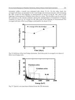
• Fatigue as a result of foreign particle
cycling
There is a great reduction in the
fatigue life when rough contaminants are
present in the bearing, fig. 44. The
harmfulness of damage caused by
foreign particles in actual cases of appli-
cation depends on their hardness, size,
and amount as well as the size of the
bearing. With regard to fatigue ball bear-
ings react more sensitively to contamina-
tion than roller bearings, and bearings
with small rolling elements more sensi-
tively than those with large ones. The
rolled-up material plays a very important
role where the indentation of foreign
particles is concerned. It is particularly
under stress during subsequent cycling
and is responsible for the first incipient
cracks, SEM fig. in section 4.
Symptoms:
Material flaking; V-shaped spreading
behind the foreign particle indentation
in cycling direction (V pitting), fig. 45.
Cause:
Damaged raceway, indentations by
hard particles (foundry sand, grinding
agent) are particularly dangerous.
Remedial measures:
– Wash housing parts thoroughly, and
coat perhaps
– Cleanliness and caution required
when mounting
– Improve sealing
– Use dirt-protected bearing construc-
tion
– Cleanliness of lubricant important
– Rinsing procedure with filtering prior
to putting unit into operation
29 FAG
Evaluation of running features and damage to dismounted bearings
Pattern of rolling contact
44: Reduction in life due to different contaminants
45: Fatigue damage caused by foreign particle indentation spreads itself in the cycling direction forming a V shape
a: Damage at the time of detection
b: Damage after about 1,000 operating hours
c: Damage after about 1,200 operating hours
0,01
0,1
1
relative life
corundum grains
foundry sand grains
grinding chips
iron chips
no contamination
• Fatigue as a result of static overload
Like foreign particle indentations,
rolling element indentations develop
due to the bearing's high static overload
and their rolled-up edges lead to failure.
Symptoms:
At the early stage evenly edged inden-
tations at rolling element spacing from
which fractures arise, often only on part
of the circumference.
Only on one ring sometimes. Usually
asymmetric to centre of raceway.
Causes:
– Static overload, shock impact
– Mounting force applied via rolling
element
Remedial measure:
– Mounting according to specification
– Avoid high impact forces, do not
overload
• Fatigue as a result of incorrect
mounting
Symptoms:
Fatigue near the small shoulder in the
case of angular contact ball bearings,
outside the contact angle area, fig. 46.
Causes:
– Insufficient adjustment
– Setting phenomenon of axial contact
areas or in thread of clamping bolts
– Radial preload
Remedial measures:
– Rigid surrounding parts
– Correct mounting
FAG 30
Evaluation of running features and damage to dismounted bearings
Pattern of rolling contact
46: Fatigue damage in groove bottom of an angular contact ball bearing's inner ring
as a result of insufficient adjustment force
• Fatigue as a result of misalignment
Symptoms:
– Track asymmetric to bearing centre,
fig. 40
– Fatigue on the edges of raceway/
rolling elements, fig. 47
– Circumferential notches on the entire
or part of ball surface caused by
plastic deformation and therefore
having smooth edges. In extreme
cases the bottoms of the notches may
have cracks, fig. 48.
Causes:
Due to housing misalignment or shaft
bending the inner ring tilts as opposed
to the outer ring and high moment loads
result. In ball bearings this leads to a
constraining force in the cage pockets
(section 3.5.4) and to more sliding in
the raceways as well as the balls running
on the shoulder edge. In the case of rol-
ler bearings, the raceway is asymmetri-
cally loaded; when tilting of the rings is
extreme, the edges of the raceways and
rolling elements also carry the load
causing excess stress in those positions,
please refer to "Tracks with misalign-
ment" in section 3.3.1.2.
Remedial measures:
– Use self-aligning bearings
– Correct misalignment
– Strengthen shaft
31 FAG
Evaluation of running features and damage to dismounted bearings
Pattern of rolling contact
47: Fatigue may occur at the edge of the raceway of a misaligned tapered roller
bearing due to local overload.
48: Fatigue at the raceway edge in the case of ball bearings, e.g. with high moment
load (edge running); left raceway edge, right ball.
• Fatigue as a result of poor lubrication
Symptoms:
Depending on the load, diverse
damage patterns arise in the case of poor
lubrication. When load is low and
slippage also occurs tiny superficial
fractures develop. Since they grow in
large numbers, they appear like spots on
the raceway, fig. 49. We refer to the
terms grey stippiness or micro pittings.
When the load is very high and the lu-
bricant has, for example, thinned down
due to water penetration, mussel-shaped
pittings develop when the raceways
(fig. 29) are also pressure polished,
fig. 50.
When loads are very high and lubrica-
tion is poor very distinct heating zones
develop in the raceway where, in turn,
incipient cracks arise when cycling con-
tinues.
Causes:
– Poor lubrication condition as a result
of
– • insufficient lubricant supply
– • operating temperature too high
– • water penetrates
– causing more friction and material
stress on the raceway surface
– Slippage at times
Remedial measures:
– Increase lubricant quantity
– Use lubricant with a higher viscosity,
if possible with tested EP additives
– Cool lubricant/bearing position
– Use softer grease perhaps
– Prevent penetration of water
FAG 32
Evaluation of running features and damage to dismounted bearings
Pattern of rolling contact
49: Micro pittings
50: Mussel-shaped fatigue
• Fatigue as a result of wear
Symptoms:
Local flaking, e.g. on the rolling ele-
ments of tapered roller bearing, figs. 51
and 52. Striped track, fig. 68.
Causes:
Change in geometry of components
in rolling contact due to wear in the case
of contaminated lubricant, for example
due to the penetration of foreign par-
ticles when sealing is damaged. Local
overload results, partly in connection
also with insufficient adjustment of
tapered roller bearings.
Remedial measures:
– Replace lubricant on time
– Filter lubricating oil
– Improve sealing
– Replace worn seals on time
– Special heat treatment for rings and
rollers
• Fatigue due to fracture in case layer
Symptoms:
Raceway peeling in thick chunks in
the case of case-hardened bearing parts.
Causes:
– Fracture or separation of case layer
– Load too high or case layer thickness
too thin for given load, e.g. due to
wrong design load
Remedial measures:
- Adjust thickness of case layer to suit
load conditions
- Avoid overloading
33 FAG
Evaluation of running features and damage to dismounted bearings
Pattern of rolling contact
51: Wear in diverse areas can change the geometry of the components in rolling
contact to such an extent that local overload leads to fatigue
a: Cross profile of a roller;
b: Inner ring raceway and roller with fatigue damage.
52: Failure mechanism as in fig. 51 but
with wear of the raceway edges, cross
profile of the roller see fig. 69.
a
b
0
0
5
1
10
15
20
25
23 567891011
mm
μm
4