Refrigeration and Air Conditioning 3 E Part 7 pps
Bạn đang xem bản rút gọn của tài liệu. Xem và tải ngay bản đầy đủ của tài liệu tại đây (277.9 KB, 30 trang )
174
Refrigeration and Air-Conditioning
trailers. Access, turning, docking and parking space is needed for
such vehicles and the loading dock should be at the tailboard height,
with adjustable ramps to allow for small differences in this. The
loading platform usually runs across the full side or end of the store
with doors opening onto it. The absolute minimum width is 3 m
and many docks are as wide as 12 m. The check-in office will be on
the dock and may have a weighbridge or rail scale for carcases. The
refrigeration machine room should have separate access.
15.2 Insulation
The purpose of insulation is to reduce heat transfer from the warmer
ambient to the store interior. Many different materials have been
used for this purpose but most construction is now with the following:
1. Cork, a natural material – the bark of the Mediterranean cork
oak tree. It is largely air cells and the fibrous cell walls have a
high resin content. When baked, the resin softens and welds
the pieces of bark into a comparatively homogeneous mass,
which is sliced into blocks, commonly 50, 75 and 100 mm thick.
2. Expanded polystyrene. The plastic is formed into beads containing
an expanding agent. When placed in a mould and heated they
swell and stick together. The blocks are then cut into thicknesses
as required.
3. Foamed polyurethane. The basic chemicals are mixed in the
liquid state with foaming agents, and swell into a low-density
foam which sets by polymerization into a rigid mass. As the
swelling material will expand into any shape required, it is ideal
for the core of sandwich panels, and the sheet material skins
may be flat or profiled. When the panels are manufactured the
mixture is injected between the inner and outer skins and expands
to the thickness required, adhering to the lining materials.
The value of an insulant to reduce heat flow is expressed as
resistivity or its reciprocal conductivity. The units of the latter are
watts per metre kelvin (W/(m K)). Values for these materials used
are approximately as follows:
Corkboard 0.04 W/(m K)
Expanded polystyrene 0.034 W/(m K)
Foamed polyurethane 0.026 W/(m K)
Example 15.4 What is the heat conduction through a panel of
foamed polyurethane 125 mm thick, 46.75 m long and 6 m high if
the inside temperature is – 25°C and the ambient is 27°C?
Cold store construction
175
Area = 46.75 × 6 = 280.5 m
2
∆T = 27 – (–25) = 52 K
Q =
280.5 52
1
0.125
0.026××
×
= 3034 W
This assumes that a wall of that size could be made of an unbroken
sheet of the insulant. Since there will be some structural breaks,
an allowance of some 5% should be added, making the leakage
3.2 kW.
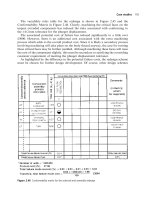
Insulation thicknesses used are 50, 75, 100, 125 and 150 mm, but
insulants can be obtained in non-standard thicknesses for special
applications. A general guide to determine the possible thickness
for a required temperature difference is to design for a conductance
of 9 W/m
2
. This gives the values in Table 15.1.
There will be exceptions to this rule, such as thicker insulation
where electric power is expensive, or thinner insulation for a chamber
only used infrequently. Ceiling panels may be thicker to give added
structural strength. In cases of doubt, the insulation costs must be
resolved as the optimum owning cost.
Table 15.1
Corkboard Expanded Foamed
polystyrene polyurethane
50 mm 11 K 13 K 17 K
75 mm 16 K 19 K 25 K
100 mm 22 K 25 K 33 K
125 mm 27 K 32 K 42 K
150 mm 32 K 38 K upwards 50 K upwards
200 mm 43 K upwards
In most cases, the insulation will be the greatest resistance to
heat flow and other materials in the construction and surface
resistances are ignored in estimating heat gains through cold store
walls, ceilings and floors.
Conductivity figures for other materials will be found in standard
references [2].
15.3 Vapour barriers
When the evaporator begins to cool a cold store, surplus moisture
in the air in the room will condense on the coil and, if cold enough,
will freeze. This will continue until the water vapour pressure inside
176
Refrigeration and Air-Conditioning
the room approaches the saturation pressure at the coil fin
temperature, e.g. with a coil temperature of – 20°C the vapour
pressure would be 0.001 bar. Since this is lower than the vapour
pressure of the ambient air, water vapour will try to diffuse from the
hot side to the cold, through the wall (see Figure 15.3). At the same
time, heat is passing through the wall, and the temperature at any
point within the insulation will be proportional to the distance
through it.
Water vapour
p
v
=1 mbar
Cold store – 10°C
Coil at – 20°C
p
v
Summer
Winter
20 mbar
6 mbar
Ambient
(a)
Ambient 27°C
Condensation
Ice–0°C
(b)
–10°C Store temperature
–20°C Coil temperature
Figure 15.3
Section through coldroom insulation.
(a) Vapour diffusion. (b) Thermal gradient
At some point through the wall, the temperature will be equal to
the saturation temperature of any water vapour passing through it,
and this vapour will condense into liquid water within the insulation.
This process will continue and the water will travel inwards until it
reaches that part of the insulation where the temperature is 0°C,
where it will freeze. The effect of water is to fill the air spaces in the
material and increase its conductivity. Ice, if formed, will expand
and split the insulant.
To prevent this deterioration of the insulation, a vapour barrier
is required across the warm face. This must be continuous and offer
the best possible barrier to the transmission of water vapour. The
traditional vapour barrier was bituminous emulsion or hot bitumen,
applied in two or more layers. More recent materials are heavy-
gauge polythene sheet, metal foil and metal sheet. It is sometimes
Cold store construction
177
thought that the plastic insulants, since they do not easily absorb
moisture, are vapour barriers. This is not so, and no reliance should
be placed on the small resistance to vapour transmission which they
may have.
Any small amount of vapour which might enter through faults in
the vapour barrier should be encouraged to pass through the inner
(cold side) skin of the structure to the coil, rather than be trapped
within the insulation. It follows that, if the vapour barrier is at all
suspect, the inner wall coating should be more porous. In traditional
construction, this was provided by an inner lining of cement plaster
or asbestos cement sheet, both of which transmit vapour. The modern
use of impervious materials on both skins requires meticulous
attention to the sealing of any joints.
Great care must be exercised at wall-to-floor junctions and all
changes of direction of walls and ceilings. In the case of a wall-to-
floor junction, this will often occur at two dissimilar types of
construction, i.e. preformed wall panels to in situ floor insulation.
A satisfactory continuous vapour barrier needs careful design.
Any conductive material, such as masonry and metal structural
members or refrigerant pipes, which must pass through the insulation,
will conduct heat, and the outer part may become cold enough to
collect condensation and ice. Such heat bridges must be insulated
for some distance, either inside or outside the main skin, to prevent
this happening. If outside, the vapour barrier must, of course, be
continuous with the main skin vapour barrier.
15.4 Sectional coldrooms
Small coldrooms can be made as a series of interlocking and fitting
sections, for assembly on site on a flat floor (see Figure 15.4). Standard
ranges are made up to about 70 m
3
, but larger stores can be made
on this principle. The floor section(s) is placed on a flat floor and
the sides erected on this, located, sealed and pulled up together.
The roof sections then bridge across the walls. Such packages are
supplied complete with all fittings. They can be dismantled and
moved to another location if required. Specialist site work is restricted
to cutting necessary holes for pipework and fitting the cooling
equipment.
Stores of this size can be built, using standard size factory-made
sandwich panels, cutting these to size, jointing and sealing on site.
This form of construction is prone to fitting errors, with subsequent
failure of the insulation, if not carried out by skilled and experienced
craftsmen. The best system can be ruined if the base is uneven or by
inexpert finishing of pipe entries, sealing, etc.
178
Refrigeration and Air-Conditioning
15.5 Inbuilt construction
Traditional cold store construction was to build an insulated lining
within a masonry shell. The outer skin would be erected in brick
and concrete, and rendered as smooth as possible inside with cement
plaster, to take the insulation. When the surface was dry, it would
have several coats of bitumen applied as a vapour barrier and slabs
of insulation material stuck to this with hot bitumen. This was normally
carried out in two or more layers so that joints did not pass right
through the insulant, but were staggered. The inner skin would be
finished with cement plaster, reinforced with wire mesh. The usual
insulant was slab cork.
Any columns passing through coldrooms would be insulated, at
least partially, to reduce conduction along the heat bridge and the
build-up of condensation and ice. Floors would have a layer of hard
concrete on the floor insulation. Ceilings were stuck to a concrete
ceiling or fixed to a false timber ceiling.
This form of construction is seen to be quite sound, and there
are still many such stores in service which were built 50 and more
years ago. The method is still used in countries where cork is cheap
and craft labour available at an economic price.
Figure 15.4
Assembly of section coldroom
(Courtesy of Hemsec (Construction) Ltd)
Cold store construction
179
15.6 Factory panel systems
The plastic insulants are rigid, homogeneous materials, suitable as
the core of sandwich panels. Such a method of fabrication is facilitated
when using foamed rigid polyurethane, since the liquids can be
made to foam between the inner and outer panel skins and have a
good natural adhesion, so making a stiff structural component [40].
Structural wall
WALL CONSTRUCTION
Sand cement render
2 layers of insulation
Surface finish
FLOOR CONSTRUCTION
Wearing surface
2 layers of insulation
Vapour barrier
Structural floor
Vapour barrier
Figure 15.5
Inbuilt coldroom (Courtesy of F. A. Wallis)
Panels made in this way for cold store and other structures are
usually 1.2 m wide and can be made in lengths of up to a maximum
of about 14 m. The manufacture incorporates interlocking edging
pieces and other fittings (see Figure 15.6). Such panels are used for
walls and ceilings, although not for floors above a certain store size.
The inner and outer skins are of aluminium or rustproofed steel
sheet, usually finished white, and may be flat or profiled. The edge
seals are plastic extrusions or similar material. The panel edge locking
devices may be built in or applied on site. To build such a store, the
floor is first prepared (see Section 15.7), bringing the vapour barrier
up at the outer face. Wall sections are erected on end on the edge
180
Refrigeration and Air-Conditioning
of the floor and locked together, making the interpanel seal at
edges and corners. Ceiling panels are fitted over the tops of the
walls and sealed at the warm face of the junction.
Since the panels must be rigid enough to support their own
weight, thickness cannot be reduced below a minimum, and this is
usually 100 mm, although less insulation might suffice for the purpose.
For a large store, panels will be 125 or possibly 150 mm thick.
The insulation panels are normally erected within a frame building
so that panel joints are protected from the weather. Long vertical
panels can be additionally braced to the structure. It is possible,
(c)
(a)
(b)
Figure 15.6
Typical wall panel mounting systems. (a) Hemsec.
(b) Isowall (O’Gorman-BTC). (c) Cape
Steadying
bracket
Roof cladding
Braced or tied
roof structure
Cladding panels
Ceiling panels
Insulated
panels
Floor
Floor insulation
Door
Loading
dock
Figure 15.7
Panel construction
Cold store construction
181
with suitable construction and finishes, to erect the insulation panels
around an internal supporting framework.
Care must be taken regarding the method of supporting ceiling
panels. Large portal framed steel buldings may provide a cheap
outer shell but do have a considerable amount of roof movement.
Panels hung from this type of structure can be subjected to movement
which cannot be tolerated in cold store construction. A tied portal,
however, can be acceptable [38]. The outer shell may also be required
to bear the weight of the evaporators and, in the case of stores for
carcase meats, the rails and the product itself.
15.7 Floors
Heavy floor loadings and the use of ride-on electric trucks demand
a strong, hard-working floor surface, which must be within the
insulation envelope.
Floor construction starts with a firm concrete foundation slab
about 200–250 mm below the final floor level. This is covered with
the vapour barrier, probably of overlapping layers of heavy-gauge
polythene sheet. On this is placed the insulation board in two layers
with staggered joints; this is fitted as tightly as possible. The upper
joints may be covered with strips of plastic to prevent concrete
running in, but a continuous layer of vapour-tight sheet must not
be used on this cold side of the insulation. The concrete floor is
made with granite aggregate, laid to the final level, as dry as possible,
reinforced with steel mesh and in panels not more than 10 m square,
to allow for contraction on cooling. Where fork-lift trucks are in
use, it is best to lay these panels with no gap, to minimize cracking
of the edges under load. If the floor will be wet in use, a finite gap
is left, and filled with mastic to prevent water getting into the
insulation.
The need for good design and expert installation of floor finishes
cannot be emphasized too strongly. The floor receives the greatest
wear of all the inner linings, and once the temperature has been
reduced in the store, it will usually remain low for the rest of its life.
Repairs are therefore very difficult.
Where a store is to take post-pallets, or will have internal racking
to store pallets, careful calculation is necessary of the load on the
feet. They can have a considerable point load, having the effect of
punching a hole through the floor finish.
15.8 Frost-heave
It floors are laid on wet ground, the vapour pressure gradient (Figure
182
Refrigeration and Air-Conditioning
15.3) will force water vapour up towards the vapour seal. Given a
ground temperature of 13°C in the UK, the underside slab may
become as cold as 0°C after many months of store operation, and
any moisture condensed under the floor insulation will freeze and,
in freezing, expand. In time this layer of ice under the floor slab,
unable to expand downwards, will lift the floor (frost-heave).
Frost-heave is prevented by supplying low-intensity heat to the
underside of the insulation, to keep it above freezing point. This
may take several forms:
1. Low-voltage electric resistance heater cables fixed to the structural
floor slab and then protected within a 50 mm thickness of cement
and sand to give a suitable surface on which the floor vapour
barrier can be laid. The heating is thermostatically controlled,
and it is usual to include a distance reading or recording
thermometer to give visual indication of the temperature of the
floor at several locations below the insulation.
2. Pipes buried in the structural slab. These are connected to delivery
and return headers, and glycol circulated. This is heated by
waste heat from the refrigeration plant. Steel pipe should not
be used under the floor unless protected against corrosion.
3. Air vent pipes to allow a current of ambient air through the
ground under the base slab. This is not very suitable in cold
climates.
4. On very damp ground or where the finished floor level is in line
with the deck of transport vehicles, the cold store floor can be
raised above the existing ground level. This is done by building
dwarf walls or extending the length of the piles, if these are
used, to support a suspended floor at the required height. This
leaves an air void of some 1 m under the cold store, through
which air can naturally circulate.
15.9 Door and safety exits
Cold store doors must combine the functions of door and insulation.
Small doors will be hinged and have an arrangement of double
gaskets to reduce the transmission of convected heat (air leakage)
and consequent ice accumulations at the door edges. Such doors
are normally wood-framed to reduce conduction, but may now have
plastic moulded frames. Insulation is by one of the foam plastics,
and the face panels are sheet metal or GRP. In order to keep the
seals in good alignment throughout the life of the door, hinges will
be made adjustable. The closing latch will have a cam or lever
action to compress the large gasket area and give a tight seal.
Cold store construction
183
Where a flush door sill is required, the gaskets on the lower edge
will be in the form of two or three flexible blades which just brush
the floor.
A simpler and more adaptable method of sealing is a face-fitting
or overlap door (Figure 15.8). The door itself overlaps the opening
by some 150 mm all round, and two or three soft gaskets seal the
overlapping surfaces. This type of door is general in rooms operating
below 0°C, and may have warming tapes embedded in the wall face
to prevent freezing of any vapour which penetrates. The smaller
sizes, and the rebated doors, are hand operated.
Larger doors, especially those to take fork-lift trucks, must be
mechanically operated for speed and convenience, and because
the doors should never be left open too long. For most purposes,
horizontal sliding doors are used, closing onto face gaskets in the
same way as the overlap doors. The slide system is generally arranged
so that the door moves out from the wall during the first part of its
travel, so as to free the gaskets and make for easier sliding. Various
electric and pneumatic mechanisms are used, and the switches for
opening and closing are controlled by toggle ropes hanging down
where the fork-lift driver can reach them without dismounting, or
by electronic sensors. Protection posts each side reduce the risk of
damage to the door frame or wall if the truck collides with them.
All mechanical doors are required by law to be capable of hand
operation in the event of power failure, and doors of all types must
have fastenings which can be opened from either side in case an
operator is shut in the store. Larger rooms must have an escape
door or breakout hatch or panel at the end remote from the doors,
for use in an emergency. Door openings are frequently fitted,
additionally, with plastic strip curtains or doors, to reduce infiltration
when the main door is open.
15.10 Interior finish and fittings
The interior surface finish, to comply with EEC and other health
standards, must be rustproof, cleanable, and free from any crevices
which can hold dirt. Bare timber in any form is not permitted. Most
liners are now aluminium or galvanized steel sheet, finished white
with a synthetic enamel or plastic coating. GRP liners are also in
use. Floors are of hard concrete or tiles. Very heavy working floors
may have metal grids let into the concrete surface. Floor concrete
is coved up at the base of the walls to form a protective curb.
In the past, timber dunnage battens were fixed around the walls
to protect the surface from collision damage and ensure an air
space for circulation of the air from the evaporators. Since timber
184
Refrigeration and Air-Conditioning
Figure 15.8
Double sliding cold store doors, power operated
(Courtesy of Clark Door Ltd)
is no longer used, dunnage may be provided in the form of metal
rails. The provision of the floor curb at the walls will ensure that
pallets cannot be stacked to prevent air circulation.
Door frame
assembly
Seals
Face and
floor heaters
Insulated
door panels
Safety lock
Protection
posts
Manual
release
Overhead
track
Operating motor
Cold store construction
185
Lighting in higher-temperature rooms is normally by fluorescent
tubes fixed to the ceiling and having starters suitable for the
temperature concerned. Low-temperature stores now mostly have
sodium or mercury vapour lamps and it is possible to obtain an
overall lighting intensity of 125 lux with an electrical load of 6 W/
m
2
floor area. Lamps must be protected so that broken glass cannot
fall onto food products. The design of efficient lighting systems
merits close attention, since all energy put into the store for lighting
must be removed again. Control switches are usually outside the
entrance doors.
Large stores must be fitted with an emergency lighting system,
battery maintained, to enable the routes to the exits to be seen
clearly in the event of a mains power failure.
15.11 Evaporators
In small cold stores, the coolers will be fixed to the walls, probably
blowing the air downwards, or to the ceiling, blowing sideways (see
Figure 7.2).
Larger evaporators (see Figure 15.9) will also be mounted at
high level if possible, to save ueful floor space. Owing to the weight,
they must be supported from the outer structural roof by tie-rods
passing through the insulation. Access gangways are needed in the
roof void to facilitate maintenance and inspection of piping, valves
and insulation. Some stores have the coolers mounted in a recess
above the loading bay, providing a maintenance platform. This can
only be done where the fans can cover the full length or width of
the chamber.
Ceiling-mounted
evaporator hung
from structural roof
(a)
(b)
Loading
dock
Cold
store
Figure 15.9
Coldroom evaporators. (a) Ceiling hung.
(b) Above loading bay
It is sometimes necessary to assist the distribution of air from the
cooler by installing air ducting. This can take the form of individual
ducts, but these are prone to damage from fork-lift trucks.
Alternatively, a full or partial false ceiling, below the insulated surface,
186
Refrigeration and Air-Conditioning
can be used. This is usually of white plastic-coated metal to match
the remainder of the lining, and the light fittings can then be fitted
flush with the underside.
15.12 Automated cold stores
The need for access by fork-lift trucks can require up to 60% of the
floor area for gangways. There are two main methods of avoiding
this wastage of store space.
Automatic stacker cranes were first used in a cold store in the
USA in 1962 and there are now many installations throughout the
world. The store height can be increased considerably, to 16–20 m,
or even higher if the rack frame is used to support the roof of the
cold store. The operation of such a store can be by using a crane
with the operator inside the store, driving the crane from a heated,
insulated cab, or can be fully automatically operated by a computer.
One crane can service some 4000 pallet positions at the rate of 50
pallets per hour.
Mobile racking – where the lines of racking are on transverse
rails, these can be closed together when access is not needed, but
rolled apart to provide an aisle for a fork-lift truck. This system is
best for a limited range of products moving in rotation, since the
racking will not have to be moved very often. A typical small
installation might have seven mobile racks, each 25 m long by four
pallets high, and require an extra 3 m width for one access aisle,
plus an end access of 4 m. This results in a store of 504 pallet
capacity and a floor area of 270 m
2
.
The tight stacking when the racks are closed impedes air flow
around the pallets, so this system is not suitable where some cooling
of the product may be required.
15.13 Security of operation
The value of the produce in a large cold store may be several times
the cost of the store itself, and every effort should be made to
maintain the refrigeration service at all times, even if plant may be
inoperative for inspection, overhaul or repair. The principle of plant
security is that there should be sufficient pieces of each item of
plant and that they should have enough capacity for conditions to
be held as required by the produce, regardless of any one item
which might be stopped [29].
Usual arrangements can be summarized as follows:
1. At least two compressors, either of which can keep the store at
temperature. It may run continuously to hold this.
Cold store construction
187
2. Two condensers, or a condenser assembly having two separate
refrigerant circuits and permitting rapair to one circuit while
the other is working. If there is one assembly with forced
convection, there are at least two fans.
3. All circulating pumps to be in duplicate, with changeover valves
to permit immediate operation.
4. At least two evaporators, to maintain conditions if one is not
working.
5. Where two compressors and two condensers are installed as
independent circuits, provide changeover valves so that either
compressor can work with either condenser or evaporator.
Before installation, the planned system should be analysed in
terms of possible component failures to ensure that it can operate
as required. Commissioning running tests should include simulated
trials of plant failure, and operatives should be made aware of failure
drills to keep the plant running.
16 Refrigeration in the food
trades – meats and fish
16.1 Meat industry applications
In the meat industry, the main applications of mechanical
refrigeration are:
Chilling of carcases directly after slaughter and dressing
Cooling of meat-handling rooms such as butcheries
Chilled water and brine for cooling poultry
Chill storage of edible meats and offal
Chilling of brine and pickling vats
Meat and poultry freezing
Animals when slaughtered, are at a body temperature of 39°C. The
carcase cools slightly as it is being dressed, but must be put into
refrigerated chambers as soon as possible [41, 42]. The speed of
cooling depends on the thickness of the joint, so the larger carcases
are usually halved into sides. While there is a need to remove body
heat to check deterioration, if this process is too quick with beef or
lamb, the resulting meat may be tough. A general rule for lean
meat such as beef is that no part should be cooled below 10°C for
at least 10 hours after slaughter, although this limit may be varied
by the local producer. The total time in this chiller stage will be
about 24 hours for a beef side [43]. Meat-cooling curves are shown
in Figure 16.1.
During the initial cooling stage, the surface of the meat will be
quite warm, and careful design of the coolers and their operation
is needed to reduce weight loss by evaporation from the surface. A
good air circulation is required at a humidity level of 90–94%, so as
to keep the surface dry without too much dehydration. In order to
maintain a good and steady air circulation around the carcases at
this time, they are hung from rails (see Figures 14.1 and 16.2).
Refrigeration in the food trades – meats and fish
189
Storage conditions in terms of air movement and humidity will
be different to those used when initially chilling the carcase. Chilled
meat on the bone is stored at about 0°C, up to the point of sale. The
humidity of the surrounding air is also critical in the case of fresh
meats – too dry and the meat will lose weight and discolour, too
humid and a slime will form on the surface.
16.2 Boned, boxed and processed meats
A lot of meat is now boned or produced as the final cuts, in the
factory. For this, the meat needs to be at 0°C or just below, i.e. just
above the temperature at which it starts to freeze hard.
This work must be carried out under hygienic and cool conditions.
The air temperature is usually not lower than 10°C, for the comfort
of the butchery staff, but some establishments work down to 2°C or
3°C. Air movement in the working area must be diffused and not
too fast, to give an acceptable environment to the operators.
Cut meats are usually wrapped or vacuum packed directly after
cutting. The viscera, bones and other parts not going for human
consumption have a byproduct value, and will probably need to be
stored at chill temperature before disposal.
Cut meats may be frozen or kept at ‘chill’ temperatures. If the
latter, the shelf life is comparatively low and the product will be
despatched almost immediately for sale.
In ‘protein economy’ processes, parts of the carcase which are
1.5
1.0
0.5
% Weight loss to 10°C deep leg
0 0.5 1.0 2.0 3.0
Air velocity (m/s)
Cooling time to 10°C
33.9
30.5
27.3
24.9
26.8
24.8
20
21.9
4°C
0°C
Figure 16.1
Effect of air velocity and temperature on the weight
loss of beef carcases [43]
190
Refrigeration and Air-Conditioning
not to be sold as joints or cuts are made up in moulds into artificial
joints, ‘gigots’ or meat loaf, in a pre-cooking operation. The made-
up product must then be cooled to about 0°C, and may then be
sliced and vacuum packed, these operations taking place in air-
conditioned rooms kept at temperatures of 10°C or lower. Most
such items are for ‘chill’ storage and immediate distribution for
sale.
There are many variations in the manner of handling and
processing meats, and these will be known only to specialist companies
in the trade. The principles of cooling are the same for all.
Meat may be frozen on the bone, but this is not a very convenient
shape for packing and handling. It is more usually boned, vacuum
wrapped, boxed and then frozen. Boxed meat sizes are about 635 ×
350 mm and 100, 125 or 150 mm thick, the largest of these holding
some 25 kg. The freezing may be in a cold air blast and the speed
of cooling will depend on the thickness of the slab (see [1–7]) and
the insulation effect of the box or wrapping (Figure 16.2). Thinner
pieces of meat can be frozen between refrigerated plates (see Figure
7.9a) [44].
–30
–20
–10
0
Air temperature (°C)
20 40 60 80 100 120
Freezing time (h) from 4 to – 7°C
0.5 m/s
5 m/s
0.5 m/s
5 m/s
0.5 m/s
5 m/s
7.3
18
6.8
12
5.1
8.7
Heat
Experimental
Predicted
Figure 16.2
Freezing time for 150 mm wrapped boxed beef
(Courtesy of AFRC Institute of Food Research, Bristol Laboratory)
16.3 Pork and bacon
Fresh pork has a shorter shelf life than beef, but is handled in the
same way and at the same chill-room temperatures. Although no
latent heat of the freezing of water content will be extracted at chill
Metal tray
Box without lid
Box with lid
Refrigeration in the food trades – meats and fish
191
temperatures, some heat will be removed when the fat ‘sets’ or
crystallizes. The quantity of heat to be removed should be estimated
and may be included in the sensible heat capacity in that temperature
range. For example, the sensible heat capacity of pork meat averages
2.5 kJ/(kg K), but a figure as high as 3.8 may be used for carcase
cooling to allow for this factor.
A high proportion of pork is pickled in brine and smoked, to
make ham or bacon. The original process was to immerse the meat
in a tank of cold brine for a period. A quicker method is to inject
the cold pickle with hypodermic needles into the cuts. Smoking is
carried out at around 52°C, so the cured bacon must be cooled
again for slicing, packing and storage.
16.4 Poultry
Poultry is immersed in hot water just after slaughter, in order to
loosen the feathers for the plucking process. The carcases are then
eviscerated and chilled as soon as possible by cold air blast or using
iced water in the form of a bath or spray.
Larger birds may be reduced to portions, so the flesh must be
cooled to about 0°C to make it firm enough for cutting. Whole
birds are prepared for cooking and then vacuum wrapped for hygiene.
Poultry may be chilled for the fresh chicken market, or frozen.
Chilling and freezing are mainly by cold air blast. Large birds such
as turkeys are wrapped and immersed in low-temperature brine
until the outside is well frozen, and then put into low-temperature
storage to freeze right through. Some poultry is frozen by spraying
with liquid carbon dioxide.
Storage of chilled poultry is at –1°C. The shelf life is relatively
short and the product will not remain in store for more than a
couple of days.
16.5 Fish
Most fish is still caught at sea and must be cooled soon after it is
taken on board, and kept cold until it can be sold, frozen or otherwise
processed [45]. The general practice is to put the fish into refrigerated
sea water tanks, kept down to 0°C by direct expansion coils or a
remote shell-and-tube evaporator. The sea water must be clean and
may be chlorine dosed. At this condition, fish can be kept for up to
four days.
Ice is also used on board, carried as blocks and crushed when
required, carried as flake, or from shipboard flake ice makers.
Artisanal fishermen in hot climates may take out crushed ice in
192
Refrigeration and Air-Conditioning
their small boats. Fresh fish is stored and transported with layers of
ice between and over the fish, cooling by conduction and keeping
the product moist. Fish kept at chill temperatures in this manner
can travel to the final point of sale, depending on the time of the
journey. Where refrigerated storage is used, the humidity within
the room must be kept high, by using large evaporators, so that the
surface of the fish does not dry.
Most vessels can now freeze their catch at sea, enabling them to
stay offshore without the need to run back to a port within the
limited life of the chilled product. If the fish is to be cleaned and
processed later, it is frozen whole, either by air blast or, more usually,
in vertical plate freezers (see Figure 7.9b), followed by frozen storage.
Some fishing vessels and the fish factory vessels will carry out cleaning,
filleting and other operations on board and then freeze and store
the final product.
A limited amount of fish is frozen by immersing it in a cold
concentrated sodium chloride brine. This is mainly tuna for
subsequent canning, or crustaceans.
Fish which is frozen in air blast will often be dipped into clean
water afterwards, resulting in a layer of ice on the surface. This
glazing process protects the fish from the effects of dehydration in
subsequent storage.
Some freezing of fish fillets and other processed fish is carried
out between or on freezer plates, in an evaporator assembly similar
to that shown in Figure 7.9a. Flat cartons of fish and fish fillets are
frozen in these horizontal plate freezers.
Health and safety requirements continue to become stricter in
the maintenance of the cold chain and the latest regulations should
be adhered to.
17 Refrigeration for the dairy,
brewing and soft drinks
industries
17.1 Milk and milk products
Milk is converted in the creamery and associated factories to whole
or ‘market’ milk, skimmed milk, creams, butters, cheeses, dried
milk, whey, yoghurts, butter oil, condensed milk, milk powder and
ice cream [46].
In the dairy industry as a whole, the main needs for mechanical
cooling are:
Cooling milk directly after it leaves the cow and before transport
to a central creamery
Keeping the raw milk cool after it enters the creamery
Chilled water for use in plate heat exchangers to cool milk and
milk products directly after pasteurizing
Chilled water to wash butter
Chill temperature stores for milk, butter, cheese, yoghurt and
other liquid milk products
Frozen storage for butter (and sometimes cheese)
Continuous, plate and air blast freezers for ice-cream
Low-temperature brine for lollipop freezing
Milk comes from the cow at about 37°C, and must be cooled within
two hours to 4°C or lower, and under hygienic conditions. At this
temperature any micro-organisms present will not multiply at a
dangerous rate and the milk can be transported to the creamery.
Dairy farms have bulk-storage tanks with their own refrigeration
plants. These are usually made in the form of a double-skin, insulated
tank, having the evaporator coils in the jacket, which also contains
water. The refrigeration system runs throughout the 24 hours and
194
Refrigeration and Air-Conditioning
builds up a layer of ice on the evaporator coils when there is no
milk cooling load. This stored cooling effect is available to help
cool the warm milk when it comes from the cow (see also Section
12.3).
Bulk tanker vehicles will not collect milk which is warmer than
4°C. If milk can be picked up from the farm at this temperature in
bulk tankers, and transported quickly enough to the creamery, then
there is no need to have refrigeration equipment on the vehicle.
On arrival at the creamery the milk is tested and transferred to
bulk-storage tanks, which may hold up to 150 t each. These will be
heavily insulated and may have some method of cooling, so as to
keep the milk down to 4°C until it passes into the processing line.
Throughout the subsequent processes, milk and milk products
will require to be re-cooled down to 4°C or thereabouts. The main
method of achieving this is to use chilled water at just above freezing
point as the secondary refrigerant. Creameries will have a large
central water-chilling system, using Baudelot coolers or evaporators
in water tanks. Some older systems are in use, but are being rapidly
replaced. Chilled water is piped to all the cooling loads within the
plant.
Whole milk for human consumption is pasteurized at 75°C for a
short time, and then re-cooled to 4°C immediately. This is done by
contraflow heat exchange between milk entering and leaving the
process, hot water and chilled water, in plate heat exchangers (see
Figure 17.1) in the following stages:
Figure 17.1
Plate heat exchangers
Support
post
Pressure
plate
Plate pack
Head plate
Connecting
plate
Refrigeration for the dairy, brewing and soft drinks industries
195
1. Raw milk at 4°C is heated by the outgoing milk up to about
71°C.
2. This milk is finally heated by hot water up to the pasteurizing
temperature of 75°C (or hotter for UHT milk) and held for a
few seconds.
3. The milk is cooled by the incoming milk, down to about 10°C.
4. The final stage of cooling from 10°C to 4°C is by chilled water
at 2°C.
Milk for other products is treated:
1. In a centrifuge to obtain cream and skim milk
2. In churning devices to make butter and buttermilk
3. With rennet to make cheese (leaving whey)
4. With cultured bacteria to make yoghurt
5. By drying, to milk powder
Butter is made from cream in continuous churning machines. At
stages during this process, the butter is washed in clean, cold water
to keep it cold and remove surplus buttermilk. At the end of the
churning stage, butter is still in a plastic state and, after packaging,
must be stored at 5°C to crystallize the fat. Long-term storage of
butter is at – 25°C.
Cheeses may be pressed into a homogeneous block, or left to
settle, depending on the type and methods of manufacture. They
then undergo a period of ripening, to give the characteristic flavour
and texture. The cold storage of cheese during the ripening period
must be under strict conditions of humidity and hygiene, or the
cheese will be damaged. Some cheeses can be frozen for long-term
storage, but must then be allowed to thaw out gradually and complete
their ripening before release to the market.
Other processes (except milk drying) require the finished product
to be cooled to a suitable storage temperature, usually 4°C or
thereabouts, and kept cool until the point of sale. Conventional-
type cold stores can be used for mixed dairy products, since all of
them will be packaged and sealed after manufacture.
17.2 Ice-cream
Ice-cream is a product which has been developed since mechanical
refrigeration became available. Ice-cream mixes comprise fats (not
always dairy), milk protein, sugar and additives such as emulsifiers,
stabilizers, colourings, together with extra items such as fruit, nuts,
pieces of chocolate, etc., according to the particular type and flavour.
The presence of this mixture of constituents means that the freezing
196
Refrigeration and Air-Conditioning
process covers a wide band of temperatures, starting just below 0°C
and not finishing until – 18°C or lower. The manufacturing process
is in three main stages – mixing, freezing to a plastic state, and
hardening.
The basic mix is made up in liquid form, pasteurized, homogenized
and cooled, using chilled water in plate heat exchangers. It is then
‘aged’ for a few hours and, for this, it will be stored at 2–3°C in
jacketed tanks, with chilled water in the jacket.
The next stage is to freeze it rapidly, with the injection of a
controlled proportion of air, to give it a light, edible texture. Aerated
mix of about 50% air, 50% ice-cream mix by volume is passed into
one end of a barrel which forms the inside of a flooded evaporator.
The mix freezes onto the inside of the barrel and is then scraped
off by rotating stainless steel beater blades, and passes through the
barrel with a continuous process of freezing, beating and blending.
The most usual refrigerant for ice-cream continuous freezers is
ammonia, which will be at an evaporating temperature of – 35°C to
– 30°C. About half of the total heat of freezing is removed in this
stage, and the ice-cream leaves at a temperature of around – 5°C,
depending on the particular type of product. A continuous ice-
cream freezer is shown in Figure 17.2.
Air filter
Air compressor
Ice-cream
mix outlet
Ice-cream mix inlet
Mutator
Freezing cylinder
Ammonia jacket
Compressed air
feed control
Manometer
Figure 17.2
Continuous ice-cream freezer (Courtesy of
Alfa-Laval Co. Ltd)
The ice-cream is still plastic as it comes from the freezer, and it is
extruded into the final sales shape – carton, tub, box, etc. It must
then be hardened by cooling down to a storage temperature of
– 25°C or lower, during which the other half of its heat of freezing
is removed.
Refrigeration for the dairy, brewing and soft drinks industries
197
Flat boxes can be hardened between refrigerated plates as shown
in Figure 7.9a. Other shapes pass through a cold air blast, and a
typical machine has a flexible conveyor belt, capable of taking a
wide variety of shapes (see Figure 17.3). An important factor of this
final freezing process is that it must be as rapid as possible, in order
to limit the size of ice crystals within the ice-cream. Rapid freezing
implies a high rate of heat transfer and, therefore, a very low
refrigerant temperature. Air blast at – 40°C is common. Two-stage
compression systems are used.
Figure 17.3
Cross-flow spiral tunnel (Courtesy of APV Baker Ltd,
Hall Division)
Ice-cream must be kept at low temperature right up to the point
of final consumption. If it is allowed to soften, the entrained air
bubbles may escape and the original texture will be lost. If it softens
and is then re-frozen, a hard, solid skin forms, making the product
inedible. Ice-cream must always be handled quickly when passing
through transit stages from the factory to consumer.
17.3 Ice lollies
Ice lollies are made from juice (water, sugar, citric acid, flavour and
colour) and are frozen into shape using moulds immersed in a cold
brine solution, in a similar manner to can ice making (see Section
12.4). The moulds are made from stainless steel or nickel, and pass
in rows through a brine bath at – 45°C. Different layers of confection
may be built up by allowing one outside layer to freeze, sucking out
the unfrozen centre and refilling with another mix. The sticks are
inserted before the centre freezes solid. The moulds finally pass
Product
out
Insulated
enclosure
Product in
Fan
Evaporator coil
198
Refrigeration and Air-Conditioning
through a defrost section of warm brine to release the lolly from
the mould, and extractor bars grab the sticks, remove the lollies
and drop them into packaging bags.
17.4 Brewing
The production of beers and ciders requires the fermentation of
sugary fluids by the action of yeasts, and the cooling, filtration,
clarification and storage of the resulting alcohol–water mixture.
The starting mix for beers is a warm brew of grain-based sugar
and flavouring. This ‘wort’ leaves the hot brewing process and is
cooled to a suitable brewing temperature – around 10°C for lagers
and 20°C for traditional bitters. This was originally carried out with
Baudelot coolers, but now plate heat exchangers are mainly used,
with chilled water as the coolant.
The process of fermentation gives off heat, and the tanks may
need to be cooled with chilled water coils, with jackets, or by cooling
the ‘cellar’ in which the tanks are located. When fermentation is
complete, many beers are now pasteurized, in the same manner as
milk (see Section 17.1). The beer is then cooled to just above freezing,
filtered and left to ‘age’. Before final bottling, kegging or canning
it will undergo a fine filtration to improve the clarity.
Refrigeration is required for the cold storage rooms and to provide
chilled water for the plate heat exchangers. The ‘cellars’ are very
wet areas, and the cooling plant should be designed to maintain as
low a humidity as possible, to help preserve the building structure.
Beers at the point of sale are traditionally stored in cellars to
keep them cool. Beers are in kegs or piped into bulk tanks. Artificial
cooling of these areas is now usual, using packaged beer cellar
coolers, somewhat similar to the air-conditioner shown in Figure
13.4. Bulk-storage tanks may have inbuilt refrigeration plant. Drinks
such as lager beer, which are normally drunk colder than other
beers, are passed through a chilled water bath or double-pipe heat
exchanger for final cooling.
Bottled beers and other drinks are kept on refrigerated trays,
comprising a cooled base tray and an inbuilt refrigeration system.
17.5 Wines and spirits
The optimum temperature of fermentation of wine depends on the
type, red wines working best at about 29°C while the white wines
require a cooler condition of around 16°C. Heat is given off by the
chemical process of fermentation. They are then traditionally matured
and stored in caves or cellars at about 10°C. Much of the manufacture