Refrigeration and Air Conditioning 3 E Part 9 doc
Bạn đang xem bản rút gọn của tài liệu. Xem và tải ngay bản đầy đủ của tài liệu tại đây (366.06 KB, 30 trang )
234
Refrigeration and Air-Conditioning
A further property which is shown on the psychrometric chart is
the specific volume of the mixture, measured in cubic metres per
kilogram. This appears as a series of diagonal lines, at intervals of
0.01 m
3
.
23.7 Effects on human comfort
The human body takes in chemical energy as food and drink, and
oxygen, and consumes these to provide the energy of the metabolism.
Some mechanical work may be done, but the greater proportion is
liberated as heat, at a rate between 90 W when resting and 440 W
when doing heavy work.
A little of this is lost by radiation if the surrounding surfaces are
cold and some as sensible heat, by convection from the skin. The
remainder is taken up as latent heat of moisture from the respiratory
tissues and perspiration from the skin (see Table 23.2). Radiant loss
will be very small if the subject is clothed, and is ignored in this
table.
Convective heat loss will depend on the area of skin exposed, the
air speed, and the temperature difference between the skin and the
Figure 23.5
Basic CIBSE psychrometric chart (Courtesy of the
Chartered Institution of Building Services Engineers)
80
60
40
20
0
Specific enthalpy (kJ/kg)
Moisture content (kg/kg) (dry air)
0.025
0.020
0.015
0.010
0.005
010203040
Dry bulb temperature (°C)
Air and water vapour mixtures
235
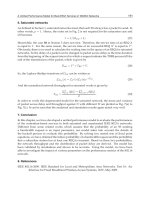
Figure 23.6
Psychrometric chart
CIBSE
PSYCHROMETRIC
CHART
Based on a barometric
pressure of 101.325 kPa
Sensible/total heat
ratio for water
added at 30°C
Specific enthalpy (kJ/kg)
Wet bulb temperature
(°C) (sling)
Specific volume
(m
3
/kg)
Percentage saturation
Dry bulb temperature (°C)
Specific enthalpy (kJ/kg)
Moisture content (kg/kg) (dry air)
236
Refrigeration and Air-Conditioning
ambient. As the dry bulb approaches body temperature (36.9°C)
the possible convective loss will diminish to zero. At the same time,
loss by latent heat must increase to keep the body cooled. This, too,
must diminish to zero when the wet bulb reaches 36.9°C.
In practice, the human body can exist in dry bulb temperatures
well above blood temperature, providing the wet bulb is low enough
to permit evaporation. The limiting factor is therefore one of wet
bulb rather than dry bulb temperature, and the closer the upper
limits are approached, the less heat can be rejected and so the less
work can be done.
23.8 Climatic conditions
Figure 23.8 shows the maximum climatic conditions in different
areas of the world. The humid tropical zones have high humidities
but the dry bulb rarely exceeds 35°C. The deserts have an arid
Figure 23.7
Reading the CIBSE psychrometric chart
Specific
enthalpy
Wet bulb
Dew point
Saturation
curve
Dry bulb
Moisture
content
%
saturation
Air and water vapour mixtures
237
Table 23.2 Heat emission from the human body (adult male, body surface area 2 m
2
)
(From CIBSE Guidebook A)
Application Sensible
(s)
and latent
(l)
heat emissions, W, at the stated dry bulb temperature
(°C)
20 22 24
Degree of activity Typical Total
(s) (l) (s) (l) (s) (l)
Seated at rest Theatre, hotel lounge 115 90 25 80 35 75 40
Light work Office, restaurant 140 100 40 90 50 80 60
Walking slowly Store, bank 160 110 50 100 60 85 75
Light bench work Factory 235 130 105 115 120 100 135
Medium work Factory, dance hall 265 140 125 125 140 105 160
Heavy work Factory 440 190 250 165 275 135 305
238
Refrigeration and Air-Conditioning
climate, with higher dry bulb temperatures. Approximate limits for
human activities are related to the enthalpy lines and indicate the
ability of the ambient air to carry away the 90–440 W of body heat.
The opposite effect will take place at the colder end of the scale.
Evaporative and convective loss will take place much more easily
and the loss by radiation may become significant, removing heat
faster than the body can generate it. The rate of heat production
can be increased by greater bodily activity, but this cannot be sustained,
so losses must be prevented by thicker insulation against convective
loss and reduced skin exposure in the form of more clothing. The
body itself can compensate by closing sweat pores and reducing the
skin temperature.
23.9 Other comfort factors
A total assessment of bodily comfort must take into account changes
in convective heat transfer arising from air velocity, and the effects
of radiant heat gain or loss. These effects have been quantified in
several objective formulas, to give equivalent, corrected effective,
globe, dry resultant and environmental temperatures, all of which
give fairly close agreement. This more complex approach is required
where air speeds may be high, there is exposure to hot or cold
surfaces, or other special conditions call for particular care.
0.030
0.029
0.028
0.027
0.026
0.025
0.024
0.023
0.022
0.021
0.020
0.019
0.018
0.017
0.016
0.015
0.014
0.013
0.012
0.011
0.010
0.009
0.008
0.007
0.006
0.005
0.004
0.003
0.002
0.001
0.000
–10 –50 51015202530354045505560
Approximate lethal limit
Moisture content (kg/kg) (dry air)
Bahrain
90 80 70 60 50 40 30 20
Percentage saturation
30
25
20
15
10
5
0
–5
–10
Wet bulb temperature
Dry bulb temperature (°C)
Acute distress
Hong Kong
Eliat
Work becomes difficult
Impaired efficiency
New
Yo r
k
Lisbon
Too warm
London
Too cold
Reykjavik
Comfort
Too cold
Kano
Wadi Halfa
Figure 23.8
Typical climate conditions
Air and water vapour mixtures
239
For comfort in normal office or residential occupation, with
percentage saturations between 35 and 70%, control of the dry
bulb will result in comfortable conditions for most persons. Feelings
of personal comfort are as variable as human nature and at any one
time 10% of the occupants of a space may feel too hot and 10% too
cold, while the 80% majority are comfortable. Such variations
frequently arise from lack or excess of local air movement, or
proximity to cold windows, rather than an extreme of temperature
or moisture content.
23.10 Fresh air
Occupied spaces need a supply of outside air to provide oxygen,
remove respired carbon dioxide, and dilute body odours and tobacco
smoke. The quantities are laid down by local regulations and
commonly call for 6–8 litre/s per occupant. Such buildings are
usually required also to have mechanical extract ventilation from
toilets and some service areas, so the fresh air supply must make up
for this loss, together with providing a small excess to pressurize the
building against ingress of dirt [2].
24 Air treatment cycles
24.1 Winter heating
Buildings lose heat in winter by conduction out through the fabric,
convection of cold air, and some radiation. The air from the con-
ditioning system must be blown into the spaces warmer than the
required internal condition, to provide the heat to counteract this
loss.
Heating methods are as follows:
1. Hot water or steam coils
2. Direct-fired – gas and sometimes oil
3. Electric resistance elements
4. Refrigerant condenser coils of heat pump or heat reclaim systems
Figure 24.1 shows the sensible heating of air.
Example 24.1 Air circulates at the rate of 68 kg/s and is to be
heated from 16°C to 34°C. Calculate the heat input and the water
mass flow for an air heater coil having hot water entering at 85°C
and leaving at 74°C.
Q = 68 × 1.02 × (34 – 16) = 1248 kW
m
w
=
1248
4.187 (85 – 74)×
= 27 kg/s
Note: the 1.02 here is a general figure for the specific heat capacity
of indoor air which contains some moisture, and is used in preference
to 1.006, which is for dry air.
Example 24.2 A building requires 500 kW of heating. Air enters
the heater coil at 19°C at the rate of 68 kg/s. What is the air-supply
temperature?
Air treatment cycles
241
Figure 24.1
Sensible heating of air
80
60
40
20
0
Specific enthalpy (kJ/kg)
25
20
15
10
5
0
Wet bulb temperature (°C) (sling)
0 10 1920 26.3 30 40
Dry bulb temperature (°C)
0.025
0.020
0.015
0.010
0.005
Moisture content (kg/kg) (dry air)
t = 19 +
500
68 1.02
= 19 + 7.2
×
= 26.2°C
If the cycle is being traced out on a psychrometric chart, the
enthalpy can be read off for the coil inlet and outlet conditions. In
Example 24.1, the enthalpy increase as measured on the chart is
7.35 kJ/kg dry air (taken at any value of humidity), giving
68 × 7.35 ~ 500 kW
24.2 Mixing of airstreams
Air entering the conditioning plant will probably be a mixture of
return air from the conditioned space and outside air. Since no
heat or moisture is gained or lost in mixing,
Sensible heat before = sensible heat after
and
242
Refrigeration and Air-Conditioning
Latent heat before = latent heat after
The conditions after mixing can be calculated, but can also be
shown graphically by a mix line joining the condition A and B (see
Figure 24.2). The position C along the line will be such that
0.025
0.020
0.015
0.010
0.005
Moisture content (kg/kg) (dry air)
0 10 2021 2830 40
Dry bulb temperature (°C)
A
C
B
0
20
40
60
80
Specific enthalpy (kJ/kg)
25
Wet bulb temperature (°C) (sling)
20
15
10
5
0
Figure 24.2
Mixing of two airstreams
AC × m
a
= CB × m
b
This straight-line proportioning holds good to close limits of accuracy.
The horizontal divisions of dry bulb temperature are almost evenly
spaced, so indicating sensible heat. The vertical intervals of moisture
content indicate latent heat.
Example 24.3 Return air from a conditioned space at 21°C, 50%
saturation, and a mass flow of 20 kg/s, mixes with outside air at
28°C dry bulb and 20°C wet bulb, flowing at 3 kg/s. What is the
condition of the mixture?
Method (a) Construct on the psychrometric chart as shown in Figure
24.2 and measure off:
Answer = 22°C dry bulb, 49% sat.
Air treatment cycles
243
Method (b) By calculation, using dry bulb temperatures along the
horizontal component, and moisture content along the
vertical. For the dry bulb, using
AC × m
a
= CB × m
b
(t
c
– 21) × 20 = (28 – t
c
) × 3
giving
t
c
= 21.9°C
The moisture content figures, from the chart or from tables, are
0.0079 and 0.0111 kg/kg at the return and outside conditions, so
(g
c
– 0.0079) × 20 = (0.0111 – g
c
) × 3
giving
g
c
= 0.0083 kg/kg
If only enthalpy is required, this can be obtained from the same
formula in a single equation:
(h
c
– h
a
) × m
a
=(h
b
– h
c
) × m
b
(h
c
– 41.8) × 20 = (56.6 – h
c
) × 3
giving
h
c
= 43.7 kJ/kg dry air
Readers will recognize that the calculation methods lend themselves
to computing.
24.3 Sensible cooling
If air at 21°C dry bulb, 50% saturation, is brought into contact with
a surface at 12°C, it will give up some of its heat by convection. The
cold surface is warmer than the dew point, so no condensation will
take place, and cooling will be sensible only (Figure 24.3).
This process is shown as a horizontal line on the chart, since
there is no change in the moisture content. The loss of sensible
heat can be read off the chart in terms of enthalpy, or calculated
from the dry bulb reduction, considering the drop in the sensible
heat of both the dry air and the water vapour in it.
24.4 Water spray (adiabatic saturation)
The effect of spraying water into an airstream will be as shown in
Figure 23.2, assuming that the air is not already saturated. Evaporation
244
Refrigeration and Air-Conditioning
will take place and the water will draw its latent heat from the air,
reducing the sensible heat and therefore the dry bulb temperature
of the air (Figure 24.4).
Example 24.4 Water is sprayed into an airstream at 21°C dry bulb,
50% saturation. What would be the ultimate condition of the mixture?
No heat is being added or removed in this process, so the enthalpy
must remain constant, and the process is shown as a movement
along the line of constant enthalpy. Latent heat will be taken in by
the water, from the sensible heat of the air, until the mixture reaches
saturation, when no more water can be evaporated.
Initial enthalpy of air = 41.08 kJ/kg
Final enthalpy of air = 41.08 kJ/kg
Final condition, 14.6°C dry bulb, 14.6°C wet bulb, 14.6°C dew
point, 100% saturated.
It should be noted that this ultimate condition is difficult to reach,
and the final condition in a practical process would fall somewhat
Figure 24.3
Sensible cooling of air
0.025
0.020
0.015
0.010
0.005
Moisture content (kg/kg) (dry air)
0 10 12 2021 30 40
Dry bulb temperature (°C)
25
20
15
10
5
0
Wet bulb temperature (°C) (sling)
0
20
40
Specific enthalpy (kJ/kg)
60
80
Air treatment cycles
245
short of saturation, possibly to point C in Figure 24.5. The proportion
AC/AB is termed the effectiveness of the spray system.
Figure 24.4
Adiabatic saturation to ultimate condition
Figure 24.5
Adiabatic saturation – process line
The adiabatic (constant enthalpy) line AC is almost parallel to
the line of constant wet bulb. Had the latter been used, the final
error would have been about 0.2 K, and it is sometimes convenient
and quicker to calculate on the basis of constant wet bulb. (This
14.6°C dry bulb
100% sat.
21°C dry bulb
50% sat.
0.025
0.020
0.015
0.010
0.005
Moisture content (kg/kg) (dry air)
0 10 2021 30 40
Dry bulb temperature (°C)
25
20
10
Wet bulb temperature (°C) (sling)
40
80
5
0
0
20
60
Specific enthalpy (kJ/kg)
B
C
A
246
Refrigeration and Air-Conditioning
correlation applies only to the mixture of dry air and water vapour,
and not to other gas mixtures.)
24.5 Steam injection
Moisture can be added to air by injecting steam, i.e. water which is
already in vapour form and does not require the addition of latent
heat (Figure 24.6). Under these conditions, the air will not be cooled
and will stay at about the same dry bulb temperature. The steam
will be at 100°C when released to the atmosphere (or may be slightly
superheated), and so raises the final temperature of the mixture.
Example 24.5 Steam at 100°C is blown into an airstream at 21°C
dry bulb, 50% saturation, at the rate of 1 kg steam/150 kg dry air.
What is the final condition?
Moisture content of air before = 0.0079 kg/kg
Moisture added, 1 kg/150 kg = 0.0067 kg/kg
Final moisture content = 0.0148 kg/kg
Figure 24.6
Addition of steam to air
0.025
0.020
0.015
0.010
0.005
Moisture content (kg/kg) (dry air)
0 10 20 22.02 30 40
Dry bulb temperature (°C)
25
20
15
10
5
0
Wet bulb temperature (°C) (sling)
0
20
40
Specific enthalpy (kJ/kg)
60
80
–0.0148
21
Air treatment cycles
247
An approximate figure for the final dry bulb temperature can be
obtained, using the specific heat capacity of the steam through the
range 20–100°C, which is about 1.972 kJ/kg. This gives
Heat lost by steam = heat gained by air
0.0067 × 1.972(100 – t) = 1.006(t – 21)
giving
t = 22.02°C
Where steam is used to raise the humidity slightly, the increase in
dry bulb temperature is small.
24.6 Air washer with chilled water
The process of adiabatic saturation in Section 24.4 assumed that
the spray water temperature had no effect on the final air condition.
If, however, a large mass of water is used in comparison with the
mass of air, the final condition will approach the water temperature.
If this water is chilled below the dew point of the entering air,
moisture will condense out of the air, and it will leave the washer
with a lower moisture content (see Figure 24.7).
The ultimate condition will be at the initial water temperature B.
Practical saturation efficiencies (the ratio AC/AB) will be about 50–
80% for air washers having a single bank of sprays and 80–95% for
double spray banks (see Figure 24.8).
Example 24.6 Air at 23°C dry bulb, 50% saturation, enters a single-
bank air washer having a saturation efficiency of 70% and is sprayed
with water at 5°C. What is the final condition?
(a) By construction on the chart (Figure 24.7), the final condition
is 10.4°C dry bulb, 82% saturation.
(b) By proportion:
Dry bulb is 70% of the way from 23°C down to 5°C
23 – [0.7(23 – 5)] = 10.4°C
Moisture content is 70% down from 0.008
9 to 0.005 4 kg/kg (i.e.
saturated air at 5°C)
0.008
9 – [0.7(0.008 9 – 0.005 4] = 0.006 45 kg/kg
Example 24.7 In Example 24.6, water is sprayed at the rate of 4 kg
water for every 1 kg air. What is the water temperature rise?
248
Refrigeration and Air-Conditioning
Figure 24.7
Air washer with chilled water
Figure 24.8
Chilled water spray
Enthalpy of air before = 45.79 kJ/kg
Enthalpy of air after = 26.7 kJ/kg
Heat lost per kilogram air = 19.09 kJ
0.025
0.020
0.015
0.010
0.005
Moisture content (kg/kg) (dry air)
Wet bulb temperature (°C) (sling)
Specific enthalpy (kJ/kg)
0 1010.4 20 23 30 40
Dry bulb temperature (°C)
C
A
25
20
15
10
B
0
0
20
40
60
80
23°C dry bulb
50% sat.
10.4°C dry bulb
82% sat.
C
5°C
Coolant
Spray
pump
Air treatment cycles
249
Heat gain per kilogram water = 19.09/4
= 4.77 kJ
Temperature rise of water =
4.77
4.187
= 1.1 K
24.7 Cooling and dehumidifying coil
In the previous process, air was cooled by close contact with a water
spray. No water was evaporated, in fact some was condensed, because
the water was colder than the dew point of the entering air.
A similar effect occurs if the air is brought into contact with a
solid surface, maintained at a temperature below its dew point.
Sensible heat will be transferred to the surface by convection and
condensation of water vapour will take place at the same time. Both
the sensible and latent heats must be conducted through the solid
and removed. The simplest form is a metal tube, and the heat is
carried away by refrigerant or a chilled fluid within the pipes. This
coolant must be colder than the tube surface to transfer the heat
inwards through the metal.
The process is indicated on the chart in Figure 24.9, taking point
B as the tube temperature. Since this would be the ultimate dew
point temperature of the air for an infinitely sized coil, the point B
is termed the apparatus dew point (ADP). In practice, the cooling
element will be made of tubes, probably with extended outer surface
in the form of fins (see Figure 7.3). Heat transfer from the air to
the coolant will vary with the fin height from the tube wall, the
materials, and any changes in the coolant temperature which may
not be constant. The average coolant temperature will be at some
lower point D, and the temperature difference B – D will be a
function of the conductivity of the coil. As air at condition A enters
the coil, a thin layer will come into contact with the fin surface and
will be cooled to B. It will then mix with the remainder of the air
between the fins, so that the line AB is a mix line.
The process line AB is shown here as a straight line for convenience
of working. Analysis of the air as it passes through a cooling coil
shows the line to be a slight curve.
The proportion AC/AB is termed the coil contact factor. The
proportion CB/AB is sometimes used, and is termed the bypass
factor.
Example 24.8 Air at 24°C dry bulb, 45% saturation, passes through
250
Refrigeration and Air-Conditioning
a coil having an ADP of 7°C and a contact factor of 78%. What is the
off-coil condition?
(a) By construction on the chart (Figure 24.9), 10.7°C dry bulb,
85% saturation.
(b) By calculation, the dry bulb will drop 78% of 24 to 7°C:
24 – [0.78 × (24 – 7)] = 10.7°C
and the enthalpy will drop 78% of 45.85 to 22.72 kJ/kg:
45.85 – [0.78 × (45.85 – 22.72)] = 27.81 kJ/kg
The two results obtained here can be compared with tabulated
figures for saturation and give about 84% saturation.
Example 24.9 Air is to be cooled by a chilled water coil from 27°C
dry bulb, 52% saturation, to 15°C dry bulb, 80% saturation. What
is the ADP?
This must be done by construction on the chart, and gives an
ADP of 9°C. The intersection of the process and saturation lines
can also be computed. Again, it has been assumed that the process
line is straight.
Figure 24.9
Cooling and dehumidifying coil – process line
0.025
0.020
0.015
0.010
0.005
Moisture content (kg/kg) (dry air)
Wet bulb temperature (°C) (sling)
Specific enthalpy (kJ/kg)
20
15
10
0
0 7 1010.7 20 24 30 40
Dry bulb temperature (°C)
A
45%
C
D
5
ADP
25
80
60
40
20
0
B
Air treatment cycles
251
24.8 Sensible–latent ratio
In all cases the horizontal component of the process line is the
change of sensible heat, and the vertical component gives the latent
heat. It follows that the slope of the line shows the ratio between
them, and the angle, if measured, can be used to give the ratio of
sensible to latent to total heat. On the psychrometric chart in general
use (Figure 23.5), the ratio of sensible to total heat is indicated as
angles in a segment to one side of the chart. This can be used as a
guide to coil and plant selection.
Example 24.10 Air enters a coil at 23°C dry bulb, 40% saturation.
The sensible heat to be removed is 36 kW and the latent 14 kW.
What are the ADP and the coil contact factor if air is to leave the
coil at 5°C?
Plotting on the chart (Figure 24.10) from 23°C/40% and using
the ratio
Sensible heat
Total heat
=
36
36 + 14
=
36
50
= 0.72
Dry bulb temperature (°C)
ADP
5
10
15
20
25
Wet bulb temperature (°C) (sling)
0
20
40
60
80
Specific enthalpy (kJ/kg)
Sensible/total
=72%
0.025
0.020
0.015
0.010
0.005
Moisture content (kg/kg) (dry air)
–1 5 10 20 23 30 40
Figure 24.10
Cooling and dehumidifying coil
252
Refrigeration and Air-Conditioning
The process line meets the saturation curve at – 1°C, giving the
ADP (which means that condensate will collect on the fins as frost).
Taking the ‘off’ condition at 5°C dry bulb and measuring the
proportion along the process line gives a coil contact factor of 75%.
24.9 Multistep processes
Some air treatment processes cannot be made in a single operation,
and the air must pass through two or more consecutive steps to
obtain the required leaving condition.
Example 24.11 If air is to be cooled and dehumidified, it may be
found that the process line joining the inlet and outlet conditions
does not meet the saturation line, e.g. in cooling air from 24°C dry
bulb, 45% saturation, to 19°C dry bulb, 50% saturation, the process
line shows this to be impossible in one step (Figure 24.11). The air
must first be cooled and dehumidified to reach the right moisture
level of 0.006 9 kg/kg and then re-heated to get it back to 19°C.
Figure 24.11
Cooling with dehumidifying, followed by re-heat –
process lines
0.025
0.020
0.015
0.010
0.005
Moisture content (kg/kg) (dry air)
0 10 1920 24 30 40
Dry bulb temperature (°C)
45%
–0.0069
25
20
10
15
5
0
Wet bulb temperature (°C) (sling)
0
20
40
80
60
Specific enthalpy (kJ/kg)
Air treatment cycles
253
The first part is identical to that in Example 24.8, and the second
step is the addition of sensible heat in a reheat coil.
Example 24.12 Winter outside air enters at 0°C dry bulb, 90%
saturation, and is to be heated to 30°C, with a moisture content of
0.012 kg/kg.
This can be done in several ways, depending on the method of
adding the moisture and final dry bulb control (see Figure 24.12).
If by steam injection, the air can be pre-heated to just below 30°C
and the steam blown in (line ABC). To give better control of the
final temperature, the steam may be blown in at a lower condition,
with final re-heat to get to the right point (line ADEC ).
90 80 70 60 50 40 30 20
Percentage saturation
30
25
20
0
5
15
10
Wet bulb temperature (°C) (sling)
E
C
Steam
Steam
Spray
Spray
0.030
0.025
0.020
0.015
0.012
0.010
0.007
0.005
0.000
0°C 5 10 15 20 25 30°C354045505560
DB
H
Dry bulb temperature (°C)
Figure 24.12
Pre-heating and humidification in winter – process lines
If by water spray or washer, the necessary heat must be put into
the air first to provide the latent heat of evaporation. This can be
done in two stages, A to F to C, or three stages A to H to J to C, if re-
heat is required to get the exact final temperature. The latter is
easier to control.
Example 24.13 Air enters a packaged dehumidifier (see Chapter
29) at 25°C dry bulb and 60% saturation. It is cooled to 10°C dry
F
254
Refrigeration and Air-Conditioning
bulb and 90% saturation, and then re-heated by its own condenser.
What is the final condition?
All of the heat extracted from the air, both sensible and latent,
passes to the refrigerant and is given up at the condenser to re-heat,
together with the energy supplied to the compressor and the fan
motor (since the latter is in the airstream). Figures for this electrical
energy will have to be determined and assessed in terms of kilojoules
per kilogram of air passing through the apparatus. A typical cycle is
shown in Figure 24.13 and indicates a final condition of about
47°C dry bulb and 10% saturation.
Figure 24.13
Dehumidifier with condenser re-heat – process lines
5
0.030
0.025
0.020
0.015
0.012
0.010
0.007
0.005
0.000
0 5 10 15 20 25°C30354045 505560
Dry bulb temperature (°C)
47°C
10%
60%
Dehumidification
90 80 70 60 50 40 30 20
Percentage saturation
30
25
20
15
10
0
Wet bulb temperature (°C) (sling)
Evaporator
duty
Condenser duty
24.10 Cycle analysis
The last three examples indicate the importance of analysis of the
required air treatment cycle on the psychrometric chart as a guide
to the methods which can be adopted and those which are not
possible. This analysis can also provide optimization of energy flows
for a process.
Direct desk calculations would have indicated the overall energy
flows between the inlet and outlet states, but may not have shown
the cycles.
25 Practical air treatment
cycles
25.1 Heating
The majority of air-conditioned buildings are offices or are used for
similar indoor activities, and are occupied intermittently. The heating
system must bring them up to comfortable working conditions by
the time work is due to start, so the heating must come into operation
earlier to warm up the building.
A large part of the heating load when operating in daytime will
be for fresh or outside air, which is not needed before occupation,
and the heat-up time will be reduced if the fresh air supply can
remain inoperative for this time.
The required warm-up time will vary with ambient conditions,
being longer in cold weather and least in warm. Optimum-start
controllers are now in general use which are programmed for the
building warm-up characteristics and sense the inside and ambient
conditions. They then transduce the required start-up period and
set the heating plant going only when needed. This, and the previous
scheme, will save fuel.
Air-cooling systems commonly have a mass flow of 0.065 kg/
(s kW) of cooling load. The normal heating load will be less than
the cooling load for most of the time and, if this full air flow is
maintained, the air inlet temperature will be of the order of 30–
32°C. This is below body temperature and may give the effect of a
cold draught, although it is heating. Where possible, the winter air
flow should be reduced to give warmer inlet air. This is particularly
so with packaged air-conditioners of all sizes, which may have to be
located for convenience rather than for the best air-flow pattern.
The addition of moisture to the winter air in the UK is not usually
necessary, except for systems using all outside air, or where persons
with severe respiratory trouble are accommodated. With a winter
256
Refrigeration and Air-Conditioning
ambient of 0°C dry bulb, 90% saturation, outside air pre-heated to
25°C will then be 17% saturation, which could itself cause discomfort.
However, this is diluted with the return air, and it is unlikely that
indoor humidities will fall below 35% saturation. Humidification of
this to 50% saturation would permit a slightly lower dry bulb (0.5 K
less) to give a similar degree of comfort, thus slightly reducing the
conduction losses from the building fabric. However, this is at the
cost of the latent heat to evaporate this moisture and a higher dew
point (10.4°C instead of 5°C) with increased condensation on cold
building surfaces and greater deterioration (see Figure 25.1).
0.025
0.020
0.015
0.010
0.005
Specific enthalpy (kJ/kg)
20
15
10
25
80
60
Moisture content (kg/kg) (dry air)
0 10 20 25 30 40
Dry bulb temperature (°C)
17%
Ambient
Return
air
Mix
0
5
Wet bulb temperature (°C) (sling)
Specific volume (m
3
/kg)
0
20
40
Figure 25.1
Pre-heating of outside air and mixing with return air –
process lines
25.2 Addition of moisture
Methods of adding moisture to the airstream (see Sections 24.4 and
24.5) are difficult to control, since a lot of water remains in the
apparatus at the moment of switching off humidification. For this
reason, the heat–humidify–re-heat cycle as shown in Figure 24.12 is
to be preferred, as the final heater control can compensate for
overshoot.
Practical air treatment cycles
257
Air washers require water treatment and bleed-off, since they
concentrate salts in the tank. Steam will be free from such impurities,
but the boiler will need attention to remove accumulations of
hardness.
Mist and spray humidifiers, unless the water is pure, will leave a
powder deposit of these salts in the conditioned space.
The use of standard factory-packaged air-conditioners to hold
close humidities, together with a separate humidifier to correct for
overdrying, is a common source of energy wastage, since both may
operate at the same time. Packaged units, unless specifically built
for the duty, will pull down to 45% saturation or lower under UK
conditions. Humidity tolerances for process conditioning such as
computer and standards rooms can often be 45–55% saturation,
and this differential gap should be wide enough to prevent simul-
taneous operation of both humidifying and dehumidifying plant.
Figure 25.2
Pre-heat, humidify, re-heat cycle – apparatus
25.3 Outside air proportion
The high internal heat load of many modern buildings means that
comfort cooling may be needed even when the ambient is down to
10°C or lower. Under these conditions, a high proportion of outside
air can remove building heat and save refrigeration energy. This
presupposes that:
1. The fresh air ducting and fan can provide more air.
2. This outside air can be filtered.
3. There are adequate automatic controls to admit this extra air
only when wanted.
4. Surplus air in the building can be extracted.
See also Chapter 34.
25.4 Cooling and dehumidification
The cooling load will always be greatest in the early afternoon, so
Cold
dry
Warm
dry
Cool
wet
Warm
humidified
HH
258
Refrigeration and Air-Conditioning
no extra start-up capacity is required. The general practice of using
a single coil for cooling and dehumidification without reheat, for
comfort cooling, will give design balance conditions only at full
load conditions. Slightly different conditions must be accepted at
other times. Closer control can be obtained by variation of the
coolant temperature and air mass flow over the coil, but such systems
can be thrown out of calibration, and measures should be taken to
avoid unauthorized persons changing the control settings or energy
will be wasted with no benefit in the final conditions.
25.5 Evaporative coolers
Many of the warmer climates have a dry atmosphere (see Figure
23.8). In such areas, considerable dry bulb temperature reduction
can be gained by the adiabatic saturation cycle (Section 24.4). The
apparatus draws air over a wetted pad and discharges it into the
conditioned space. It is termed an evaporative or desert cooler
(Figure 25.3).
Example 25.1 Air at 37°C dry bulb, 24% saturation, is drawn through
a desert cooler having an adiabatic saturation efficiency of 75%.
What is the final dry bulb, and how much water is required?
The entering enthalpy is 62.67 kJ/kg, and this remains constant
through the process.
By construction on the chart, or from tables, the ultimate saturation
condition would be 21.5°C, and 75% of the drop from 37°C to
21.5°C gives a final dry bulb of 25.4°C.
The water requirement can be calculated from the average latent
heat of water over the working range, which is 2425 kJ/kg. The
amount of water to be evaporated is 1/2425 = 0.4 × 10
–3
kg/(s kW).
This process is very much used for ambient control in textile
mills and, to a lesser extent, in greenhouses for vegetable production
in hot, dry climates.
A two-stage evaporative cooler (Figure 25.4) uses the cooled water
from the first stage to pre-cool the air entering the second stage.
The two air systems are separate. Outside air is drawn through the
first stage (Figure 25.4), passing through the upper wetted pad,
and so cools the water down to a temperature approaching the
ambient wet bulb. This chilled water then circulates through a dry
coil to cool another supply of outside air, thus reducing its wet bulb
temperature. This second-stage air then passes through the lower
wetted pad and into the cooled space. Water make-up is required to
both circuits.