Mobile Robots Navigation 2008 Part 2 pps
Bạn đang xem bản rút gọn của tài liệu. Xem và tải ngay bản đầy đủ của tài liệu tại đây (2.4 MB, 40 trang )
MobileRobotsNavigation28
center axis is Z, the angle along the cone-wise plane from the line OA to an arbitrary
position C is θ, the rotating angle of the cone-wise plane around the Z-axis is φ, the angle
between the line of vision (ray axis) and the ground is γ, and the inclined angle of the
mother line is γ
0
. We can obtain next formulas from the above geometrical relation,
cos φ = cos (2θ)
(3a)
sin φ = cos ( γ- γ
0
) sin (2θ)
(3b)
If we assume the relation γ = γ
0
, we can get
φ = 2θ .
(4)
In the above relation, the angle θ means the angle of the polarizing plane based on the line
OA. Hence we can extend the polarizing angle θ in the range of 180(deg) to the rotating
angle of the cone-wise plane φ in the range of 360(deg). Since both angles are one-to-one
correspondence, we can determine the azimuth angle uniquely. When the sharpness of the
cone-wise plane is the angle γ
0
, the extending shape of the cone-wise plane is determined
uniquely as shown in Fig. 2. and we can get the next relation
γ
0
= 30(deg) .
(5)
Then we can show that the rotating angle of the cone-wise plane around the Z-axis can be
modulated as the angle of the polarizing plane around the ray axis. That is, if we set a light
source inside the cone-wise polarizer and observe from outside the cone-wise plane, the
angle of the observed polarizing plane is proportional to the rotating angle of the cone-wise
plane.
O
A
B
C
θ
e-vector
plane
expansion
for
m
O
A
B
C
θ
z
φ
γ
0
γ
ground
O'
Fig. 2. 3-D conic structure made by flexible linear polarizer
3.2 Compensation of Discontinuity
There is an adhered part that is parallel to the mother line in the manufactured cone-wise
polarizer structurally. If we use a single cone-wise polarizer, sensing information is
discontinuous and influenced polarizing properties at the junction. So we use two cone-wise
polarizers as shown in Fig. 3. and assign them at distorted angles each other for
compensating discontinuity.
O
1
A
B
C
z
E
D
F
θ
2
φ
cone 1
A
B
C
O'
C
A
O
B
e-vector
plane
F
D
O
E
e-vector
plane
θ
1
θ
2
cone 2
E
D
F
θ
1
+ θ
2
= (π/2) ;C=F
O
2
junction point of cone 2junction point of cone 1
θ
1
Fig. 3. Elimination of constructional discontinuity
4. Measuring Principle of Distance
4.1 Distance Determination by Elevation Angle
At indoor environment, we image the working space with the constant distance from the
floor to the ceiling. We set an infrared landmark to a ceiling and we assume that the
landmark is located at the arbitrary ceiling in the working space. The light coming from a
landmark is correctly caught on the directive principal axis by the sensor attached to the
robot. If it assumes that the height H from floor to the ceiling is constant, the horizontal
OpticalAzimuthSensorforIndoorMobileRobotNavigation 29
center axis is Z, the angle along the cone-wise plane from the line OA to an arbitrary
position C is θ, the rotating angle of the cone-wise plane around the Z-axis is φ, the angle
between the line of vision (ray axis) and the ground is γ, and the inclined angle of the
mother line is γ
0
. We can obtain next formulas from the above geometrical relation,
cos φ = cos (2θ)
(3a)
sin φ = cos ( γ- γ
0
) sin (2θ)
(3b)
If we assume the relation γ = γ
0
, we can get
φ = 2θ .
(4)
In the above relation, the angle θ means the angle of the polarizing plane based on the line
OA. Hence we can extend the polarizing angle θ in the range of 180(deg) to the rotating
angle of the cone-wise plane φ in the range of 360(deg). Since both angles are one-to-one
correspondence, we can determine the azimuth angle uniquely. When the sharpness of the
cone-wise plane is the angle γ
0
, the extending shape of the cone-wise plane is determined
uniquely as shown in Fig. 2. and we can get the next relation
γ
0
= 30(deg) .
(5)
Then we can show that the rotating angle of the cone-wise plane around the Z-axis can be
modulated as the angle of the polarizing plane around the ray axis. That is, if we set a light
source inside the cone-wise polarizer and observe from outside the cone-wise plane, the
angle of the observed polarizing plane is proportional to the rotating angle of the cone-wise
plane.
O
A
B
C
θ
e-vector
plane
expansion
for
m
O
A
B
C
θ
z
φ
γ
0
γ
ground
O'
Fig. 2. 3-D conic structure made by flexible linear polarizer
3.2 Compensation of Discontinuity
There is an adhered part that is parallel to the mother line in the manufactured cone-wise
polarizer structurally. If we use a single cone-wise polarizer, sensing information is
discontinuous and influenced polarizing properties at the junction. So we use two cone-wise
polarizers as shown in Fig. 3. and assign them at distorted angles each other for
compensating discontinuity.
O
1
A
B
C
z
E
D
F
θ
2
φ
cone 1
A
B
C
O'
C
A
O
B
e-vector
plane
F
D
O
E
e-vector
plane
θ
1
θ
2
cone 2
E
D
F
θ
1
+ θ
2
= (π/2) ;C=F
O
2
junction point of cone 2junction point of cone 1
θ
1
Fig. 3. Elimination of constructional discontinuity
4. Measuring Principle of Distance
4.1 Distance Determination by Elevation Angle
At indoor environment, we image the working space with the constant distance from the
floor to the ceiling. We set an infrared landmark to a ceiling and we assume that the
landmark is located at the arbitrary ceiling in the working space. The light coming from a
landmark is correctly caught on the directive principal axis by the sensor attached to the
robot. If it assumes that the height H from floor to the ceiling is constant, the horizontal
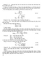
MobileRobotsNavigation30
distance from the transmitter to the receiver can be calculated from the elevation of the
receiver as shown in Fig. 4. If the elevation angle β is measured, the horizontal distance L
between a transmitter and a receiver will be obtained by
tan
H
L
.
(6)
Fig. 4. Experimental setup
4.2 Elevation Angle Measurement using Accelerometer
An elevation angle is measured from the plane of the floor. With the ideal level, a floor is not
always horzontal but there is an inclination and unsmoothness. When the cart of the mobile
robot with the sensor may incline, the measured result of the elevation angle might be
included some errors. So we measure the elevation angle on the basis of gravity acceleration.
We measure gravity acceleration using a semiconductor-type acceleration sensor and
acquire an elevation angle from the ratio of gravity acceleration which acts on each axis. If
the robot is stationary, downward gravity acceleration will act on a sensor. An acceleration
sensor has specific axes which shows higher sensitivity. In this research, we call them
sensitivity axes.
Distance:L
Azimuth:θ
Light Axis
Elevation:β
Height:H
tripod
Receiver
Guide rail
cart
Transmitter
Fig. 5. Accelerometer and sensitivity axis
We set a sensitivity axis perpendicular to downward direction with β' as the preparation of
measurements as shown in Fig. 5. An output voltage from gravity acceleration V
out
which
acts along a single sensitivity axis is expressed in the following
V
out
= K
s
G
0
cos β' + V
offset
.
(7)
Here K
s
is the sensor gain , G
0
is constant gravity accerelation and V
offset
is offset voltage of
the sensor which adjust to zero in advance. Differentiating (7) about β', we get
V
diff
= - K
s
G
0
sin β' .
(8)
We know, the closer a sensitivity axis approaches vertically from horizontal axis, the worse
the sensitivity of an acceleration sensor becomes.
4.3 Improvement of the measureing precision
When the elevation angle β in eq.(6) is include the measuring error ∆β , we get
tantan
tantan1
)tan(
H
H
LL
.
(9)
By Eqs.(6) and (9), the distance error ∆L is shown as follows
tan
1
tantan
tantan1
HL
.
(10)
accelerometer
sensitivity axis
gravity
acceleratio
n
elevation
G
0
OpticalAzimuthSensorforIndoorMobileRobotNavigation 31
distance from the transmitter to the receiver can be calculated from the elevation of the
receiver as shown in Fig. 4. If the elevation angle β is measured, the horizontal distance L
between a transmitter and a receiver will be obtained by
tan
H
L
.
(6)
Fig. 4. Experimental setup
4.2 Elevation Angle Measurement using Accelerometer
An elevation angle is measured from the plane of the floor. With the ideal level, a floor is not
always horzontal but there is an inclination and unsmoothness. When the cart of the mobile
robot with the sensor may incline, the measured result of the elevation angle might be
included some errors. So we measure the elevation angle on the basis of gravity acceleration.
We measure gravity acceleration using a semiconductor-type acceleration sensor and
acquire an elevation angle from the ratio of gravity acceleration which acts on each axis. If
the robot is stationary, downward gravity acceleration will act on a sensor. An acceleration
sensor has specific axes which shows higher sensitivity. In this research, we call them
sensitivity axes.
Distance:L
Azimuth:θ
Light Axis
Elevation:β
Height:H
tripod
Receiver
Guide rail
cart
Transmitter
Fig. 5. Accelerometer and sensitivity axis
We set a sensitivity axis perpendicular to downward direction with β' as the preparation of
measurements as shown in Fig. 5. An output voltage from gravity acceleration V
out
which
acts along a single sensitivity axis is expressed in the following
V
out
= K
s
G
0
cos β' + V
offset
.
(7)
Here K
s
is the sensor gain , G
0
is constant gravity accerelation and V
offset
is offset voltage of
the sensor which adjust to zero in advance. Differentiating (7) about β', we get
V
diff
= - K
s
G
0
sin β' .
(8)
We know, the closer a sensitivity axis approaches vertically from horizontal axis, the worse
the sensitivity of an acceleration sensor becomes.
4.3 Improvement of the measureing precision
When the elevation angle β in eq.(6) is include the measuring error ∆β , we get
tantan
tantan1
)tan(
H
H
LL
.
(9)
By Eqs.(6) and (9), the distance error ∆L is shown as follows
tan
1
tantan
tantan1
HL
.
(10)
accelerometer
sensitivity axis
gravity
acceleratio
n
elevation
G
0
MobileRobotsNavigation32
In the height H is constant value(H=2.0(m)), the relation between distance error and
elevation angle error is shown as Fig. 6, in the case of d = 0.1 , 1 , 5 and 10 (m).
Fig. 6. Distance error vs elevation measurement error
Gravity acceralation on the stationally body is always constantly downward 1.0(G). If we
assume components of the acceleration X
G
(G) and Y
G
(G), with the inclination angle β(deg)
of mutually orthogonal principle axes of accelerations, β
*
is satisfied with the following
0
1
*
cos
GK
V
sx
xout
x
.
(11a)
0
1
*
cos
GK
V
sx
yout
y
.
(11b)
When we measure the acceleration among which axis, we get the elevation on that axis.
In the elevation angle measurement of using single axis, the measureing presition is
remarkably decreased by the non-linearity of the trigonometric function at the specified
angles.
The sensitivity of the gravity acceleration affects on that of the elevation angle at the
proximity of the angle which the principle axis is parallel to the vartical axis. We
compensate the elevation angle measurement by using multi axes in the following two
approaches so that we consider the angle range of confirming more presize measurement.
(a) Right angle switching method; for excluding the angle range of principle axes with the
remarkably worth precision, we use the single axes of more suitable axis. Such the angle
β
*
(deg) is including the range of 0 ≤ β < 45, 135 ≤ β < 225 and 315 ≤ β < 360, we use the angle
on the X-axis and otherwise we use the angle on the Y-axis. i.e.
elevation measurement error Δβ(degrees)
distance error ΔL(m)
L=10(m)
L= 5(m)
L= 1(m)
L=0.1(m)
315β225,135β45
360β315,225β135,45β0
;
;
*
*
*
)(
y
x
a
.
(12)
(b) Weighting method; the way of measureing angle without switching axis that we put the
more weight as more principle axis is closer to horizontal direction and vice versa. If we
make the voltage V
x
(V),V
y
(V) and the angle of β
x
*
(deg),β
y
*
(deg)of each axis, we can get the
weighting average as follows,
yx
x
y
yx
y
xb
VV
V
VV
V
***
)(
.
(13)
We use the electric capacity type 3-axes semiconductor acceleration sensor (Kionix KXM52-
1050). Sensitivity axes of this sensor cross orthogonal mutually. We measured the elevation
angle using two of three sensitivity axes V
out x
and V
out y
.
An X-axis positive direction is defined as 0 (deg), Y-axis positive direction is 90 (deg) and Z-
axis is perpendicular to the X-Y plane. That is used as rotation axis in this experiment. Next,
we adjust offset and gain of an accelerometer that X-axis output voltage V
out x
to 0(V) when
the X
0
axis is 0(deg), Y-axis output voltage V
out y
to 0(V) when the X-axis is 90(deg). We
regard the angle set by the angle-setup apparatus as the true value in X-axis direction. Then
we adjust each 5(deg) in the range of 0 ~ 355(deg) and we compare the error between the
angle calculated from accelerometer output (angle measurement) and that of the evaluated
value. In addition, we compare and evaluate on two ways that uses two axes.
method β
*
x
only
β
*
y
only Right angle switching Weighting
maximum error (deg) 1.479 2.860 0.321 0.294
variance 6.37e-2
1.88e-1 3.26e-2 5.49e-2
S.D. 2.52e-1
4.33e-1 1.81e-1 2.34e-1
Table 1. Relationship of measurement error
The table1 summarize the angle error of the masured angle and the true one by calculating
measured data on one axis or two axes. In all items, the two-axis measureing accuracy is
better than that of the data by single axis. Additionally in two-axis measurement by using a
weighting method, the maximum error seems to be improved. By using the weighting
method, the maximum error in the best case is suppressed under the 1/10 value when
compared with the single axis. The maximum elevation error obtained by weighting method
is 0.294(deg). If we calculate the distance error from this result, eventhough the distance L
from the experimental apparatus in Fig. 4 to the target point is 10(m), the error of the
distance is about 0.3(m). Therefore, this measuring apparatus and technique can confirm the
high precision on the distance measurement. We employed the weighting method for
distance measurement.
OpticalAzimuthSensorforIndoorMobileRobotNavigation 33
In the height H is constant value(H=2.0(m)), the relation between distance error and
elevation angle error is shown as Fig. 6, in the case of d = 0.1 , 1 , 5 and 10 (m).
Fig. 6. Distance error vs elevation measurement error
Gravity acceralation on the stationally body is always constantly downward 1.0(G). If we
assume components of the acceleration X
G
(G) and Y
G
(G), with the inclination angle β(deg)
of mutually orthogonal principle axes of accelerations, β
*
is satisfied with the following
0
1
*
cos
GK
V
sx
xout
x
.
(11a)
0
1
*
cos
GK
V
sx
yout
y
.
(11b)
When we measure the acceleration among which axis, we get the elevation on that axis.
In the elevation angle measurement of using single axis, the measureing presition is
remarkably decreased by the non-linearity of the trigonometric function at the specified
angles.
The sensitivity of the gravity acceleration affects on that of the elevation angle at the
proximity of the angle which the principle axis is parallel to the vartical axis. We
compensate the elevation angle measurement by using multi axes in the following two
approaches so that we consider the angle range of confirming more presize measurement.
(a) Right angle switching method; for excluding the angle range of principle axes with the
remarkably worth precision, we use the single axes of more suitable axis. Such the angle
β
*
(deg) is including the range of 0 ≤ β < 45, 135 ≤ β < 225 and 315 ≤ β < 360, we use the angle
on the X-axis and otherwise we use the angle on the Y-axis. i.e.
elevation measurement error Δβ(degrees)
distance error ΔL(m)
L=10(m)
L= 5(m)
L= 1(m)
L=0.1(m)
315β225,135β45
360β315,225β135,45β0
;
;
*
*
*
)(
y
x
a
.
(12)
(b) Weighting method; the way of measureing angle without switching axis that we put the
more weight as more principle axis is closer to horizontal direction and vice versa. If we
make the voltage V
x
(V),V
y
(V) and the angle of β
x
*
(deg),β
y
*
(deg)of each axis, we can get the
weighting average as follows,
yx
x
y
yx
y
xb
VV
V
VV
V
***
)(
.
(13)
We use the electric capacity type 3-axes semiconductor acceleration sensor (Kionix KXM52-
1050). Sensitivity axes of this sensor cross orthogonal mutually. We measured the elevation
angle using two of three sensitivity axes V
out x
and V
out y
.
An X-axis positive direction is defined as 0 (deg), Y-axis positive direction is 90 (deg) and Z-
axis is perpendicular to the X-Y plane. That is used as rotation axis in this experiment. Next,
we adjust offset and gain of an accelerometer that X-axis output voltage V
out x
to 0(V) when
the X
0
axis is 0(deg), Y-axis output voltage V
out y
to 0(V) when the X-axis is 90(deg). We
regard the angle set by the angle-setup apparatus as the true value in X-axis direction. Then
we adjust each 5(deg) in the range of 0 ~ 355(deg) and we compare the error between the
angle calculated from accelerometer output (angle measurement) and that of the evaluated
value. In addition, we compare and evaluate on two ways that uses two axes.
method β
*
x
only
β
*
y
only Right angle switching Weighting
maximum error (deg) 1.479 2.860 0.321 0.294
variance 6.37e-2
1.88e-1 3.26e-2 5.49e-2
S.D. 2.52e-1
4.33e-1 1.81e-1 2.34e-1
Table 1. Relationship of measurement error
The table1 summarize the angle error of the masured angle and the true one by calculating
measured data on one axis or two axes. In all items, the two-axis measureing accuracy is
better than that of the data by single axis. Additionally in two-axis measurement by using a
weighting method, the maximum error seems to be improved. By using the weighting
method, the maximum error in the best case is suppressed under the 1/10 value when
compared with the single axis. The maximum elevation error obtained by weighting method
is 0.294(deg). If we calculate the distance error from this result, eventhough the distance L
from the experimental apparatus in Fig. 4 to the target point is 10(m), the error of the
distance is about 0.3(m). Therefore, this measuring apparatus and technique can confirm the
high precision on the distance measurement. We employed the weighting method for
distance measurement.
MobileRobotsNavigation34
5. Experimental Setup
5.1 Introduction
The proposed sensor consists of two parts. One is the transmitter which emits polarized-
modulating infrared rays. Another is the receiver which demodulates infrared rays from the
transmitter. Thus we can acquire the heading of the receiver's azimuth. By using the
transmitter as the landmark, we measure a self-position and absolute azimuth of the
receiver. A schematic view of an experimental setup is shown in Fig. 4. The transmitter is
attached to a tripod at the height of 1700(mm) from the floor. The vertex direction of conic
polarizer corresponds to downward. Since the transmitter can rotate arround a
perpendicular axis, it can set arbitrary azimuth angle. The receiver is installed to the cart on
the straight rail for setting arbitarary horizontal distance. Setting the height of the receiver to
200(mm) with the cart, we can get the height of H=1500(mm) between the transmitter and
the receiver.
5.2 Transmitter
The transmitter plays the most important role in this sensor. It consists of an infrared LED
array, a pulse generating circuit, and a conic linear polarizer. If the LED is driven by a
narrow duty pulse with a subcarrier frequency of 1(MHz), momentary optical power can be
increased and we make the signal easy to distinguish from the disturbance light which
comes out of lighting apparatus. The infrared rays emitted from LED have strong
directivity, and the light intensity which comes out of single LED is weak. In order to keep
the strong light intensity, seven LEDs have been arranged over 1 turn. Since the polarizing
plane is discontinuous at the jointed line on the cone, we want to shut off the light at this
point. We employed a special idea and made a sophisticated device that we used to combine
two modules with mutually different direction of jointed line. The block diagram of the
transmitter is shown in Fig. 7. Actual size of conic linear polarizer is about 50(mm) diameter.
Fig. 7. Block diagram of the transmitter
monostable
multi-vibrator
linear-polarizer
(conic shape)
Power
AMP
IR LED array
Ext.
inpu
OSC
1[MHz]
selector
linear-polarized IR
O
A
B
C
θ
z
φ
γ
0
O'
5.3 Receiver
A receiver is constituted by a convex lens, a rotating light polarizer, a photo detector, a
preamplifier, and an AM receiving circuit. The mechanical structure of a receiver is shown
in Fig. 8. The light coming from the transmitter is first condensed with a convex lens about
35(mm) diameter. Next, the light is passed through the polarizer attached to the small DC
motor, which made an amplitude modulation (AM) signal, and a photo detector. The motor
has a rotation-synchronized pulse generator. The light which entered into the photo detector
is changed into an electric signal, and is inputted into the AM receiving circuit through a
preamplifier. The AM receiving circuit is equivalent to the AM middle wave radio in of a
superheterodyne system. Thus, the light signal is convert to the phase between the
synchronized pulse and the sine wave depend on the angle of polarizing plane. The signal
frequency is twice of a motor speed as an AF band approximately 400(Hz). A received signal
is taken into PC from A/D conversion through after a low pass filter. Based on the pulse
outputted from a motor, the phase of a received sine wave-like signal is proportional to the
angle of the linear polarization of the light from the transmitter. Therefore, we will be
obtained that the angle around the perpendicular axis of a transmitter by calculate the phase
difference.
Fig. 8. Mechanical structure of the receiver (fragment)
6. Experimental Result and Discussion
6.1 Azimuth Measurement
A transmitter is rotated every 10 degrees and azimuth angles at specified ones among 1 turn
are measured. The distance from a transmitter to a receiver is influenced by the measuring
error of angles. When we change the distance L as the Fig. 4 from 1000(mm) to 3000(mm) at
each 500(mm), the measured results of the angle is shown in Fig. 9. Also Fig. 10 shows the
measurement angle error. The alignment relation is obtained within 4% at all over the
distance range. When the linear polarized light is transmitted inside of the free space where
a refractivity does not change, a polarizing plane is maintained. Therefore, angle
measurement is not influenced even if distance changes theoretically. However, if the
distance from a transmitter to a receiver increases, as a result of a signal declination, in a
long distance, the S/N ratio may deteriorate and angle measurement may be affected. The
receiver for an experiment rotates the polarizer using the motor, and can obtain the angle of
light axis
photo
detector
convex
lens
motor
linear
polarizer
linear
polarizer
front view side view
OpticalAzimuthSensorforIndoorMobileRobotNavigation 35
5. Experimental Setup
5.1 Introduction
The proposed sensor consists of two parts. One is the transmitter which emits polarized-
modulating infrared rays. Another is the receiver which demodulates infrared rays from the
transmitter. Thus we can acquire the heading of the receiver's azimuth. By using the
transmitter as the landmark, we measure a self-position and absolute azimuth of the
receiver. A schematic view of an experimental setup is shown in Fig. 4. The transmitter is
attached to a tripod at the height of 1700(mm) from the floor. The vertex direction of conic
polarizer corresponds to downward. Since the transmitter can rotate arround a
perpendicular axis, it can set arbitrary azimuth angle. The receiver is installed to the cart on
the straight rail for setting arbitarary horizontal distance. Setting the height of the receiver to
200(mm) with the cart, we can get the height of H=1500(mm) between the transmitter and
the receiver.
5.2 Transmitter
The transmitter plays the most important role in this sensor. It consists of an infrared LED
array, a pulse generating circuit, and a conic linear polarizer. If the LED is driven by a
narrow duty pulse with a subcarrier frequency of 1(MHz), momentary optical power can be
increased and we make the signal easy to distinguish from the disturbance light which
comes out of lighting apparatus. The infrared rays emitted from LED have strong
directivity, and the light intensity which comes out of single LED is weak. In order to keep
the strong light intensity, seven LEDs have been arranged over 1 turn. Since the polarizing
plane is discontinuous at the jointed line on the cone, we want to shut off the light at this
point. We employed a special idea and made a sophisticated device that we used to combine
two modules with mutually different direction of jointed line. The block diagram of the
transmitter is shown in Fig. 7. Actual size of conic linear polarizer is about 50(mm) diameter.
Fig. 7. Block diagram of the transmitter
monostable
multi-vibrator
linear-polarizer
(conic shape)
Power
AMP
IR LED array
Ext.
inpu
OSC
1[MHz]
selector
linear-polarized IR
O
A
B
C
θ
z
φ
γ
0
O'
5.3 Receiver
A receiver is constituted by a convex lens, a rotating light polarizer, a photo detector, a
preamplifier, and an AM receiving circuit. The mechanical structure of a receiver is shown
in Fig. 8. The light coming from the transmitter is first condensed with a convex lens about
35(mm) diameter. Next, the light is passed through the polarizer attached to the small DC
motor, which made an amplitude modulation (AM) signal, and a photo detector. The motor
has a rotation-synchronized pulse generator. The light which entered into the photo detector
is changed into an electric signal, and is inputted into the AM receiving circuit through a
preamplifier. The AM receiving circuit is equivalent to the AM middle wave radio in of a
superheterodyne system. Thus, the light signal is convert to the phase between the
synchronized pulse and the sine wave depend on the angle of polarizing plane. The signal
frequency is twice of a motor speed as an AF band approximately 400(Hz). A received signal
is taken into PC from A/D conversion through after a low pass filter. Based on the pulse
outputted from a motor, the phase of a received sine wave-like signal is proportional to the
angle of the linear polarization of the light from the transmitter. Therefore, we will be
obtained that the angle around the perpendicular axis of a transmitter by calculate the phase
difference.
Fig. 8. Mechanical structure of the receiver (fragment)
6. Experimental Result and Discussion
6.1 Azimuth Measurement
A transmitter is rotated every 10 degrees and azimuth angles at specified ones among 1 turn
are measured. The distance from a transmitter to a receiver is influenced by the measuring
error of angles. When we change the distance L as the Fig. 4 from 1000(mm) to 3000(mm) at
each 500(mm), the measured results of the angle is shown in Fig. 9. Also Fig. 10 shows the
measurement angle error. The alignment relation is obtained within 4% at all over the
distance range. When the linear polarized light is transmitted inside of the free space where
a refractivity does not change, a polarizing plane is maintained. Therefore, angle
measurement is not influenced even if distance changes theoretically. However, if the
distance from a transmitter to a receiver increases, as a result of a signal declination, in a
long distance, the S/N ratio may deteriorate and angle measurement may be affected. The
receiver for an experiment rotates the polarizer using the motor, and can obtain the angle of
light axis
photo
detector
convex
lens
motor
linear
polarizer
linear
polarizer
front view side view
MobileRobotsNavigation36
-
2.50
-
1.25
0.00
1.25
2.5
0
L1000
L1500
L2000
L2500
L3000
setting angle (degrees)
relative error (%)
0
30
60
90
12
0
1
50
1
80
21
0
24
0
2
70
300
330
0
90
180
270
360
0
30
60
90
12
0
1
50
1
80
21
0
24
0
2
70
300
330
setting angle (degrees)
measured angle ( degrees)
L 1000
L 1500
L 2000
L 2 500
L 3 000
polarization from the phase. If the rotation speed of a motor changes, since the generated
delay in LPF will change relatively, the measurement accuracy of a phase deteriorates.
Fig. 9. Measured angle vs set azimuth angle (L:mm)
Fig. 10. Measurement error of azimuth angle (L:mm)
0
1000
2000
3000
1000 1500 2000 2500 3000
setting distance (mm)
measured distance (mm)
A polarizing plate is not moved mechanically but the detecting method of an angle from the
strength of the signal from two or more sensors is also discussed (see references). While, in
order to receive the light of a transmitter from several meters away, we have to set light axis
precisely. It is difficult to configure two or more sensors with same properties exactly. If we
employ the two or more divided type monolithic photodiode, it may solve to the problem to
some extent. However, we have to attach the polarizing plate adjusted to the angle in front
of each element. Our system should be considered as only one optical sensor in total. If the
speed of a motor can be stabilized more accurately we expect the measurement accuracy of
the direction angle to increase.
6.2 Localization Measurement
Fig. 11 depicts the distance measurement result. Relation between setting distance and
measured one is linear. The latter shows less than the former. In this experiment, the
absolute maximum error is 93(mm) at set distanse of 3000(mm). Finally, we get Fig. 12
which is whole result of the experiment. This r-θ plot illustrates that estimated position of a
mobile robot using our sensor system. Of course, the center is a landmark.
Fig. 11. Measured distance vs set distance
OpticalAzimuthSensorforIndoorMobileRobotNavigation 37
-
2.50
-
1.25
0.00
1.25
2.5
0
L1000
L1500
L2000
L2500
L3000
setting angle (degrees)
relative error (%)
0
30
60
90
12
0
1
50
1
80
21
0
24
0
2
70
300
330
0
90
180
270
360
0
30
60
90
12
0
1
50
1
80
21
0
24
0
2
70
300
330
setting angle (degrees)
measured angle ( degrees)
L 1000
L 1500
L 2000
L 2 500
L 3 000
polarization from the phase. If the rotation speed of a motor changes, since the generated
delay in LPF will change relatively, the measurement accuracy of a phase deteriorates.
Fig. 9. Measured angle vs set azimuth angle (L:mm)
Fig. 10. Measurement error of azimuth angle (L:mm)
0
1000
2000
3000
1000 1500 2000 2500 3000
setting distance (mm)
measured distance (mm)
A polarizing plate is not moved mechanically but the detecting method of an angle from the
strength of the signal from two or more sensors is also discussed (see references). While, in
order to receive the light of a transmitter from several meters away, we have to set light axis
precisely. It is difficult to configure two or more sensors with same properties exactly. If we
employ the two or more divided type monolithic photodiode, it may solve to the problem to
some extent. However, we have to attach the polarizing plate adjusted to the angle in front
of each element. Our system should be considered as only one optical sensor in total. If the
speed of a motor can be stabilized more accurately we expect the measurement accuracy of
the direction angle to increase.
6.2 Localization Measurement
Fig. 11 depicts the distance measurement result. Relation between setting distance and
measured one is linear. The latter shows less than the former. In this experiment, the
absolute maximum error is 93(mm) at set distanse of 3000(mm). Finally, we get Fig. 12
which is whole result of the experiment. This r-θ plot illustrates that estimated position of a
mobile robot using our sensor system. Of course, the center is a landmark.
Fig. 11. Measured distance vs set distance
MobileRobotsNavigation38
Fig. 12. Localization result of our sensor system.
7. Conclusion
We can acquire simultaneously both the azimuth angle and the distance from the target
position by using a single landmark. This sensing system is constructed by combination of
the optical sensor using infrared linear polarizer which developed by authors and the
commercial semiconductor type of acceleration sensor. By using a semiconductor
acceleration sensor, experiments on the elevation angle were measured based on the
direction of gravity. It is very useful to acquire the information on the position and the angle
in the indoor environment.
O
100
0
200
0
300
0
0
30
60
90
12
0
15
0
180
210
33
0
3 0
0
270
24
0
distance(mm)
azimuth(deg)
8. References
D.Lambrinos, M.Maris, H.Kobayashi, T.Labhart, R.Pfeifer and R.Wehner (1997), "An
Autonomous Agent Navigating with a Polarized Light Compass", Adaptive behavior,
Vol.6-No.1 ,pp.131-161
K.Atsuumi, M.Hashimoto and M.Sano(2008). "Optical Azimuth Sensor for Indoor Mobile Robot
Navigation", The 2008 International Conference on Computer Engineering &
Systems(ICCES'08), ISBN:978-1-4244-2116-9, Cairo, Egypt.
M.Yamamoto, N.Ushimi and A.Mohri(1999-Mar), "Navigation Algorithm for Mobile Robots
using Information of Target Direction", Trans.JSME,Vol.65-No.631,pp.1013-1020.
(in Japanese)
N.Ushimi, M.Yamamoto and A.Mohri(2000-Mar), "Development of a Two Degree-of-Freedom
Target Direction Sensor System for Localization of Mobile Robots", Trans.JSME, Vol.66-
No.643, pp.877-884. (in Japanese)
Japanese patent No.2001-221660(2001) (in Japanese)
Japanese patent No.H08-340475(1996) (in Japanese)
OpticalAzimuthSensorforIndoorMobileRobotNavigation 39
Fig. 12. Localization result of our sensor system.
7. Conclusion
We can acquire simultaneously both the azimuth angle and the distance from the target
position by using a single landmark. This sensing system is constructed by combination of
the optical sensor using infrared linear polarizer which developed by authors and the
commercial semiconductor type of acceleration sensor. By using a semiconductor
acceleration sensor, experiments on the elevation angle were measured based on the
direction of gravity. It is very useful to acquire the information on the position and the angle
in the indoor environment.
O
100
0
200
0
300
0
0
30
60
90
12
0
15
0
180
210
33
0
3 0
0
270
24
0
distance(mm)
azimuth(deg)
8. References
D.Lambrinos, M.Maris, H.Kobayashi, T.Labhart, R.Pfeifer and R.Wehner (1997), "An
Autonomous Agent Navigating with a Polarized Light Compass", Adaptive behavior,
Vol.6-No.1 ,pp.131-161
K.Atsuumi, M.Hashimoto and M.Sano(2008). "Optical Azimuth Sensor for Indoor Mobile Robot
Navigation", The 2008 International Conference on Computer Engineering &
Systems(ICCES'08), ISBN:978-1-4244-2116-9, Cairo, Egypt.
M.Yamamoto, N.Ushimi and A.Mohri(1999-Mar), "Navigation Algorithm for Mobile Robots
using Information of Target Direction", Trans.JSME,Vol.65-No.631,pp.1013-1020.
(in Japanese)
N.Ushimi, M.Yamamoto and A.Mohri(2000-Mar), "Development of a Two Degree-of-Freedom
Target Direction Sensor System for Localization of Mobile Robots", Trans.JSME, Vol.66-
No.643, pp.877-884. (in Japanese)
Japanese patent No.2001-221660(2001) (in Japanese)
Japanese patent No.H08-340475(1996) (in Japanese)
MobileRobotsNavigation40
VisionBasedObstacleDetectionModuleforaWheeledMobileRobot 41
VisionBasedObstacleDetectionModuleforaWheeledMobileRobot
OscarMontiel,AlfredoGonzálezandRobertoSepúlveda
0
Vision Based Obstacle Detection
Module for a Wheeled Mobile Robot
Oscar Montiel, Alfredo González and Roberto Sepúlveda
Centro de Investigación y Desarrollo de Tecnología Digital
del Instituto Politécnico Nacional.
México
1. Introduction
Navigation in mobile robotic ambit is a methodology that allows guiding a mobile robot (MR)
to accomplish a mission through an environment with obstacles in a good and safe way, and it
is one of the most challenging competence required of the MR. The success of this task requires
a good coordination of the four main blocks involved in navigation: perception, localization,
cognition, and motion control. The perception block allows the MR to acquire knowledge
about its environment using sensors. The localization block must determine the position of
the MR in the environment. Using the cognition block the robot will select a strategy for
achieving its goals. The motion control block contains the kinematic controller, its objective
is to follow a trajectory described by its position (Siegwart & Nourbakhsh, 2004). The MR
should possess an architecture able to coordinate the on board navigation elements in order
to achieve correctly the different objectives specified in the mission with efficiency that can be
carried out either in indoor or outdoor environments.
In general, global planning methods complemented with local methods are used for indoor
missions since the environments are known or partially known; whereas, for outdoor missions
local planning methods are more suitable, becoming global planning methods, a complement
because of the scant information of the environment.
In previous work, we developed a path planning method for wheeled MR navigation using a
novel proposal of ant colony optimization named SACOdm (Simple Ant Colony Optimization
with distance (d) optimization, and memory (m) capability), considering obstacle avoidance
into a dynamic environment (Porta et al., 2009). In order to evaluate the algorithm we used
virtual obstacle generation, being indispensable for real world application to have a way of
sensing the environment.
There are several kind of sensors, broadly speaking they can be classified as passive and ac-
tive sensors. Passive sensors measure the environmental energy that the sensor receives, in
this classification some examples are microphones, tactile sensors, and vision based sensors.
Active sensors, emit energy into the environment with the purpose of measuring the environ-
mental reaction. It is common that an MR have several passive and/or active sensors; in our
MR, for example, the gear motors use optical quadrature encoders, it uses a high precision
GPS for localization, and two video cameras to implement a stereoscopic vision system for
object recognition and localization of obstacles for map building and map reconstruction.
3
MobileRobotsNavigation42
This work presents a proposal to achieve stereoscopic vision for MR application, and its devel-
opment and implementation into VLSI technology to obtain high performance computation
to improve local and global planning, obtaining a faster navigation by means of reducing idle
times due to slow computations. Navigation using ant colony environment is based on map
building and map reconfiguration; in this model, every ant is a virtual MR. The MR system,
composed by the MR and the global planner in the main computer, see Fig 1, has the task to
construct the map based on a representation of the environment scene, avoiding the use of
Landmarks to make the system more versatile. The MR stereo vision transforms the visual
information of two 2D images of the same scene environment into deep measure data. Hence,
the MR sends this data via RF to the global planner in the main computer; this data is a 3D
representation of the MR scene environment and its local position and orientation. By this
way, the optimal path in the environment is constantly updated by the global planner.
The MR stereo vision has the advantage, with respect to other navigation techniques, that
depth can be inferred with no prior knowledge of the observed scene, in particular the scene
may contain unknown moving objects and not only motionless background elements.
For the environment map construction and reconfiguration, the MR makes an inference of
the three dimensional structure of a scene from its two dimensional 2D projections. The 3D
description of the scene is obtained from different viewpoints. With this 3D description we
are able to recreate the environment map for use in robot navigation.
In general, in any stereoscopic vision system after the initial camera calibration, correspon-
dence is found among a set of points in the multiple images by using a feature based ap-
proach. Disparity computation for the matched points is then performed. Establishing cor-
respondences between point locations in images acquired from multiple views (matching) is
one of the key tasks in the scene reconstruction based on stereoscopic image analysis. This
feature based approach involves detecting the feature points and tracking their positions in
multiple views of the scene. Aggarwal presented a review of the problem in which they dis-
cussed the developments in establishing stereoscopic correspondence for the extraction of the
3D structure (Aggarwal et al., 2000). A few well-known algorithms representing widely dif-
ferent approaches were presented, the focus of the review was stereoscopic matching.
For map construction or reconfiguration of the MR obstacles environment there is not neces-
sary to reconstruct an exact scene of the environment. There are other works in the same line,
in (Calisi et al., 2007) is presented an approach that integrates appearance models and stereo-
scopic vision for decision people tracking in domestic environments. In (Abellatif, 2008) the
author used a vision system for obstacle detection and avoidance, it was proposed a method
to integrate the behavior decisions by using potential field theory (Khatib, 1985) with fuzzy
logic variables. It was used Hue, Saturation, and Intensity (HSI) color since it is perceptually
uniform. In (Cao, 2001) was presented an omnidirectional vision camera system that pro-
duces spherical field of view of an environment, the continuation of this work was presented
in (Cao et al., 2008) where the authors explained several important issues to consider for using
fisheye lens in omnidirectional vision, some of them are the lens camera calibration, rectifica-
tion of the lens distortion, the use of a particle filter for tracking, as well as the algorithms and
the hardware configuration that they implemented.
Recently, the company “Mobile Robots” announced a heavy duty high speed stereoscopic
vision system for robots called “MobileRanger StereoVision System”, that is able to provide
processed images at a maximal rate of 60 fps (frames per second) with a resolution of 752
× 480
pixels.
The proposed method has some advantages over existing methods, for example it does not
need camera calibration for depth (distance) estimation measurements; an improved effi-
ciency in the stereoscopic correspondence for block matching; adaptive candidate matching
window concept is introduced for stereoscopic correspondence for block matching resulting
in improved efficiency by reducing calculation time, also improves matching accuracy as-
suring corresponding process only in the areas where there are vertical or corners arranged
pixels corresponding to the obstacles selected features. The calculation process is reduced
in average 40% corresponding to the surface ground image content which is previously ex-
tracted from every image. The areas between edges in the obstacles itself are also excluded
from matching process. This is an additional increase in the method efficiency by reducing
calculation for matching process. This feature provides the optimal choice of the best com-
ponent of the video signal giving improvements in precision of architecture based on FPGA
implementation of a vision module for obstacle detection, for map building and dynamic map
reconfiguration as an extension research of the ant colony environment model described in a
previous work (Porta et al., 2009).
This work is organized as follows: In section 2 the general system architecture is explained.
Section 3 is dedicated to give a description of the process to extract the surface ground and
obstacle edge detection using luminance components, as well as the process when we include
the Hue to obtain the ground surface, moreover, in this section we comment some advantages
obtained with the implementation of the vision module into an FPGA. In Section 4 some
important concepts about stereoscopic vision are given. In Section 5 is explained how the
modification of the road map is achieved. Finally, in Section 6 are the conclusions.
2. General System Overview
Figure 1 shows the two main components of the system architecture, the computer, and the
MR:
1. The computer contains the global planner based on the SACOdm algorithm, and the
communication system.
2. The MR is a three wheels system with frontal differential tracking, it has six main sub-
systems:
(a) The stereoscopic vision includes parallel arrange dedicated purpose video de-
coders controlled via IIC by the FPGA.
(b) The Spartan-3 FPGA controller board that contains embedded the Microblaze mi-
crocontroller, as well as the motors and tracking controllers that were coded in
VHDL hardware description language software.
(c) The power module consists of a high capacity group of rechargeable batteries
(not shown in the figure), two H-bridges motor drivers, and the two Pittman DC
geared-motor model GM9236S025-R1.
(d) The communication system based on the XbeePro RF, integrated WiFi communi-
cation module.
(e) A high accuracy GPS module with 1 cm of resolution, 0.05% of accuracy, such as
the VBOX 3i from Racelogic (VBOX, 2009), or similar.
(f) An electromagnetic custom made compass IIC bus compatible, based on the
LIS3LV02DL integrated circuit from STMicroelectronics.
VisionBasedObstacleDetectionModuleforaWheeledMobileRobot 43
This work presents a proposal to achieve stereoscopic vision for MR application, and its devel-
opment and implementation into VLSI technology to obtain high performance computation
to improve local and global planning, obtaining a faster navigation by means of reducing idle
times due to slow computations. Navigation using ant colony environment is based on map
building and map reconfiguration; in this model, every ant is a virtual MR. The MR system,
composed by the MR and the global planner in the main computer, see Fig 1, has the task to
construct the map based on a representation of the environment scene, avoiding the use of
Landmarks to make the system more versatile. The MR stereo vision transforms the visual
information of two 2D images of the same scene environment into deep measure data. Hence,
the MR sends this data via RF to the global planner in the main computer; this data is a 3D
representation of the MR scene environment and its local position and orientation. By this
way, the optimal path in the environment is constantly updated by the global planner.
The MR stereo vision has the advantage, with respect to other navigation techniques, that
depth can be inferred with no prior knowledge of the observed scene, in particular the scene
may contain unknown moving objects and not only motionless background elements.
For the environment map construction and reconfiguration, the MR makes an inference of
the three dimensional structure of a scene from its two dimensional 2D projections. The 3D
description of the scene is obtained from different viewpoints. With this 3D description we
are able to recreate the environment map for use in robot navigation.
In general, in any stereoscopic vision system after the initial camera calibration, correspon-
dence is found among a set of points in the multiple images by using a feature based ap-
proach. Disparity computation for the matched points is then performed. Establishing cor-
respondences between point locations in images acquired from multiple views (matching) is
one of the key tasks in the scene reconstruction based on stereoscopic image analysis. This
feature based approach involves detecting the feature points and tracking their positions in
multiple views of the scene. Aggarwal presented a review of the problem in which they dis-
cussed the developments in establishing stereoscopic correspondence for the extraction of the
3D structure (Aggarwal et al., 2000). A few well-known algorithms representing widely dif-
ferent approaches were presented, the focus of the review was stereoscopic matching.
For map construction or reconfiguration of the MR obstacles environment there is not neces-
sary to reconstruct an exact scene of the environment. There are other works in the same line,
in (Calisi et al., 2007) is presented an approach that integrates appearance models and stereo-
scopic vision for decision people tracking in domestic environments. In (Abellatif, 2008) the
author used a vision system for obstacle detection and avoidance, it was proposed a method
to integrate the behavior decisions by using potential field theory (Khatib, 1985) with fuzzy
logic variables. It was used Hue, Saturation, and Intensity (HSI) color since it is perceptually
uniform. In (Cao, 2001) was presented an omnidirectional vision camera system that pro-
duces spherical field of view of an environment, the continuation of this work was presented
in (Cao et al., 2008) where the authors explained several important issues to consider for using
fisheye lens in omnidirectional vision, some of them are the lens camera calibration, rectifica-
tion of the lens distortion, the use of a particle filter for tracking, as well as the algorithms and
the hardware configuration that they implemented.
Recently, the company “Mobile Robots” announced a heavy duty high speed stereoscopic
vision system for robots called “MobileRanger StereoVision System”, that is able to provide
processed images at a maximal rate of 60 fps (frames per second) with a resolution of 752
× 480
pixels.
The proposed method has some advantages over existing methods, for example it does not
need camera calibration for depth (distance) estimation measurements; an improved effi-
ciency in the stereoscopic correspondence for block matching; adaptive candidate matching
window concept is introduced for stereoscopic correspondence for block matching resulting
in improved efficiency by reducing calculation time, also improves matching accuracy as-
suring corresponding process only in the areas where there are vertical or corners arranged
pixels corresponding to the obstacles selected features. The calculation process is reduced
in average 40% corresponding to the surface ground image content which is previously ex-
tracted from every image. The areas between edges in the obstacles itself are also excluded
from matching process. This is an additional increase in the method efficiency by reducing
calculation for matching process. This feature provides the optimal choice of the best com-
ponent of the video signal giving improvements in precision of architecture based on FPGA
implementation of a vision module for obstacle detection, for map building and dynamic map
reconfiguration as an extension research of the ant colony environment model described in a
previous work (Porta et al., 2009).
This work is organized as follows: In section 2 the general system architecture is explained.
Section 3 is dedicated to give a description of the process to extract the surface ground and
obstacle edge detection using luminance components, as well as the process when we include
the Hue to obtain the ground surface, moreover, in this section we comment some advantages
obtained with the implementation of the vision module into an FPGA. In Section 4 some
important concepts about stereoscopic vision are given. In Section 5 is explained how the
modification of the road map is achieved. Finally, in Section 6 are the conclusions.
2. General System Overview
Figure 1 shows the two main components of the system architecture, the computer, and the
MR:
1. The computer contains the global planner based on the SACOdm algorithm, and the
communication system.
2. The MR is a three wheels system with frontal differential tracking, it has six main sub-
systems:
(a) The stereoscopic vision includes parallel arrange dedicated purpose video de-
coders controlled via IIC by the FPGA.
(b) The Spartan-3 FPGA controller board that contains embedded the Microblaze mi-
crocontroller, as well as the motors and tracking controllers that were coded in
VHDL hardware description language software.
(c) The power module consists of a high capacity group of rechargeable batteries
(not shown in the figure), two H-bridges motor drivers, and the two Pittman DC
geared-motor model GM9236S025-R1.
(d) The communication system based on the XbeePro RF, integrated WiFi communi-
cation module.
(e) A high accuracy GPS module with 1 cm of resolution, 0.05% of accuracy, such as
the VBOX 3i from Racelogic (VBOX, 2009), or similar.
(f) An electromagnetic custom made compass IIC bus compatible, based on the
LIS3LV02DL integrated circuit from STMicroelectronics.
MobileRobotsNavigation44
The communication between the MR and the computer is achieved using the XBeePro RF
Modules that meets the IEEE 802.15.4 standards, the modules operates within the ISM (In-
dustrial Scientific and Medical) 2.4 GHz frequency band. The range of application for in-
door/urban range is 100 meters (m), and for outdoor applications with RF line of sight the
range is about 1500 m. The serial data rate is in between 1200 bits per second (bps) to 250 kilo
bits per second (kbps) (XBee XBee OEM RF Modules, 2007). With no hardware modification it
is possible to change the RF module to the XBee-Pro XSC to improve the communication range
from 370 m for indoor/urban applications, and 9.6 Km for outdoor line sight applications.
Fig. 1. The global planner is in the computer communicated through RF with the MR, this is
shown in 1). In 2) is the MR with its main components: a) the cameras, b) FPGA system board,
c) H bridge motor drivers, d) RF communication system based on the Zigbee technology, e)
Magnetic Compass, f) GPS module, g) Gear Pittman DC-motors, h) NTSC Composite video
to RGB converter cards.
In Fig. 2 a more detailed description of the stereoscopic vision system is given, each video
camera is connected to a conversion board from NTSC composite video to RGB 24 bits video
signals, which in turn are controlled by the FPGA based controller board using IIC commu-
nication. The video cards send the video information to the controller board where it is pro-
cessed.
Fig. 3 shows the Microblaze processor, it is a 32 bit soft core processor with Harvard architec-
ture embedded into a Xilinx FPGA. The Microblaze allows to customize its architecture for a
specific application. It can manage 4 GB of memory. The 32 bits Local Memory Bus (LMB)
connects the processor’s core to the RAM Memory Blocks (BRAM) for data (DLMB) and in-
struction (ILMB) handling. The Microblaze uses the Processor Local Bus (PLB) also called
On-Chip Peripheral Bus (OPB) to connect different slave peripherals (SPLB) with the CPU,
for data and instruction exchange it uses the DPLB and IPLB, respectively. In the figure are
connected also to the Microblaze core: The peripherals PWM, RS232, IIC, Timer, etc. These
last modules were designed for specific application and glued to the Microblaze architecture.
An important feature of this processor is that also contains the Microprocessor Debug Module
(MDM) that gives the possibility to achieve real time debugging using the JTAG interface. The
stereoscopic vision module was programmed using ANSI C/C++ language.
Fig. 2. Detailed overview of subsystems of the Stereoscopic vision stage on board of the MR.
Fig. 3. Microblaze processor embedded into Xilinx FPGA and system peripherals.
3. Description of the Detection Module with Stereoscopic Vision
The navigation task is achieve using the relative depth representation of the obstacles based
on stereoscopic vision and the epipolar geometry. The map represents the status at the time
of drawing the map, not necessarily consistent with the actual status of the environment at
the time of using the map. Mapping is the problem of integrating the information gathered in
this case by the MR sensors into a complex model and depicting with a given representation.
Stereo images obtained from the environment are supplied to the MR, by applying disparity
algorithm on stereo image pairs, depth map for the current view is obtained. A cognitive map
of the environment is updated gradually with the depth information extracted while the MR
VisionBasedObstacleDetectionModuleforaWheeledMobileRobot 45
The communication between the MR and the computer is achieved using the XBeePro RF
Modules that meets the IEEE 802.15.4 standards, the modules operates within the ISM (In-
dustrial Scientific and Medical) 2.4 GHz frequency band. The range of application for in-
door/urban range is 100 meters (m), and for outdoor applications with RF line of sight the
range is about 1500 m. The serial data rate is in between 1200 bits per second (bps) to 250 kilo
bits per second (kbps) (XBee XBee OEM RF Modules, 2007). With no hardware modification it
is possible to change the RF module to the XBee-Pro XSC to improve the communication range
from 370 m for indoor/urban applications, and 9.6 Km for outdoor line sight applications.
Fig. 1. The global planner is in the computer communicated through RF with the MR, this is
shown in 1). In 2) is the MR with its main components: a) the cameras, b) FPGA system board,
c) H bridge motor drivers, d) RF communication system based on the Zigbee technology, e)
Magnetic Compass, f) GPS module, g) Gear Pittman DC-motors, h) NTSC Composite video
to RGB converter cards.
In Fig. 2 a more detailed description of the stereoscopic vision system is given, each video
camera is connected to a conversion board from NTSC composite video to RGB 24 bits video
signals, which in turn are controlled by the FPGA based controller board using IIC commu-
nication. The video cards send the video information to the controller board where it is pro-
cessed.
Fig. 3 shows the Microblaze processor, it is a 32 bit soft core processor with Harvard architec-
ture embedded into a Xilinx FPGA. The Microblaze allows to customize its architecture for a
specific application. It can manage 4 GB of memory. The 32 bits Local Memory Bus (LMB)
connects the processor’s core to the RAM Memory Blocks (BRAM) for data (DLMB) and in-
struction (ILMB) handling. The Microblaze uses the Processor Local Bus (PLB) also called
On-Chip Peripheral Bus (OPB) to connect different slave peripherals (SPLB) with the CPU,
for data and instruction exchange it uses the DPLB and IPLB, respectively. In the figure are
connected also to the Microblaze core: The peripherals PWM, RS232, IIC, Timer, etc. These
last modules were designed for specific application and glued to the Microblaze architecture.
An important feature of this processor is that also contains the Microprocessor Debug Module
(MDM) that gives the possibility to achieve real time debugging using the JTAG interface. The
stereoscopic vision module was programmed using ANSI C/C++ language.
Fig. 2. Detailed overview of subsystems of the Stereoscopic vision stage on board of the MR.
Fig. 3. Microblaze processor embedded into Xilinx FPGA and system peripherals.
3. Description of the Detection Module with Stereoscopic Vision
The navigation task is achieve using the relative depth representation of the obstacles based
on stereoscopic vision and the epipolar geometry. The map represents the status at the time
of drawing the map, not necessarily consistent with the actual status of the environment at
the time of using the map. Mapping is the problem of integrating the information gathered in
this case by the MR sensors into a complex model and depicting with a given representation.
Stereo images obtained from the environment are supplied to the MR, by applying disparity
algorithm on stereo image pairs, depth map for the current view is obtained. A cognitive map
of the environment is updated gradually with the depth information extracted while the MR
MobileRobotsNavigation46
Fig. 4. Process in the detection module for surface ground extraction, and obstacles edge
detection using luminance component.
is exploring the environment. The MR explores its environment using the current views, if
an obstacle in its path is observed, the information of the target obstacles in the path will be
send to the global planner in the main computer. After each movement of the MR in the envi-
ronment, stereo images are obtained and processed in order to extract depth information. For
this purpose, obstacle’s feature points, which are obstacle edges, are extracted from the im-
ages. Corresponding pairs are found by matching the edge points, i.e., pixel’s features which
have similar vertical orientation. After performing the stereo epipolar geometry calculation,
depth for the current view is extracted. By knowing the camera parameters, location, and
orientation, the map can be updated with the current depth information.
3.1 Surface Ground and Obstacles Detection Using Luminance and Hue
The vision based obstacle detection module classifies each individual image pixel as belong-
ing either to an obstacle or the ground. Appearance base method is used for surface ground
classification and extraction from the MR vision module captured images, see Fig. 4. Any
pixel that differs in appearance from the ground is classified as an obstacle. After surface
ground extraction, remaining image content are only obstacles. A combination of pixel
appearance and feature base method is used for individual obstacle detection and edge
extraction. Obstacles edges are more suitable for stereo correspondence block matching in
order to determine the disparity between left and right images. For ground surface extraction
purpose, two assumptions were established that are reasonable for a variety of indoor and
Fig. 5. Process in the detection module for surface ground extraction using Hue, and obstacles
edge detection using luminance components.
outdoor environments:
1. The ground is relatively flat.
2. Obstacles differ in color appearance from the ground. This difference is reasonable and
can be subjectively measured as Just Noticeably Difference (JND), which is reasonable
for a real environment.
Above assumptions allow us to distinguish obstacles from the ground and to estimate the
distances between detected obstacles from the vision based system. The classification of a
pixel as representing an obstacle or the surface ground can be based on local visual attributes:
Intensity, Hue, edges, and corners. Selected attributes must provide information so that the
system performs reliably in a variety of environments. Selected attributes should also require
low computation time so that real time system performance can be achieved. The less compu-
tational cost has the attribute, the obstacle detection update rate is greater, and consequently
the MR travel faster and safer.
For appearance classification we used Hue as a primary attribute for ground surface detection
and extraction, see Fig. 5. Hue provides more stable information than color or luminance
based on pixel gray level. Color saturation and luminance perceived from an object is affected
by changes in incident and reflected lightness. Also compared to texture, Hue is more local
attribute and faster to calculate. In general, Hue is one of the main properties of a color,
VisionBasedObstacleDetectionModuleforaWheeledMobileRobot 47
Fig. 4. Process in the detection module for surface ground extraction, and obstacles edge
detection using luminance component.
is exploring the environment. The MR explores its environment using the current views, if
an obstacle in its path is observed, the information of the target obstacles in the path will be
send to the global planner in the main computer. After each movement of the MR in the envi-
ronment, stereo images are obtained and processed in order to extract depth information. For
this purpose, obstacle’s feature points, which are obstacle edges, are extracted from the im-
ages. Corresponding pairs are found by matching the edge points, i.e., pixel’s features which
have similar vertical orientation. After performing the stereo epipolar geometry calculation,
depth for the current view is extracted. By knowing the camera parameters, location, and
orientation, the map can be updated with the current depth information.
3.1 Surface Ground and Obstacles Detection Using Luminance and Hue
The vision based obstacle detection module classifies each individual image pixel as belong-
ing either to an obstacle or the ground. Appearance base method is used for surface ground
classification and extraction from the MR vision module captured images, see Fig. 4. Any
pixel that differs in appearance from the ground is classified as an obstacle. After surface
ground extraction, remaining image content are only obstacles. A combination of pixel
appearance and feature base method is used for individual obstacle detection and edge
extraction. Obstacles edges are more suitable for stereo correspondence block matching in
order to determine the disparity between left and right images. For ground surface extraction
purpose, two assumptions were established that are reasonable for a variety of indoor and
Fig. 5. Process in the detection module for surface ground extraction using Hue, and obstacles
edge detection using luminance components.
outdoor environments:
1. The ground is relatively flat.
2. Obstacles differ in color appearance from the ground. This difference is reasonable and
can be subjectively measured as Just Noticeably Difference (JND), which is reasonable
for a real environment.
Above assumptions allow us to distinguish obstacles from the ground and to estimate the
distances between detected obstacles from the vision based system. The classification of a
pixel as representing an obstacle or the surface ground can be based on local visual attributes:
Intensity, Hue, edges, and corners. Selected attributes must provide information so that the
system performs reliably in a variety of environments. Selected attributes should also require
low computation time so that real time system performance can be achieved. The less compu-
tational cost has the attribute, the obstacle detection update rate is greater, and consequently
the MR travel faster and safer.
For appearance classification we used Hue as a primary attribute for ground surface detection
and extraction, see Fig. 5. Hue provides more stable information than color or luminance
based on pixel gray level. Color saturation and luminance perceived from an object is affected
by changes in incident and reflected lightness. Also compared to texture, Hue is more local
attribute and faster to calculate. In general, Hue is one of the main properties of a color,
MobileRobotsNavigation48
defined as the degree of perceived stimulus described as Red, Green, and Blue. When a pixel
is classified as an obstacle, its distance from the MR stereo vision cameras system is estimated.
The considerations for the surface ground extraction and obstacle edge detection for corre-
spondences block matching are:
1. Color image from each video camera is converted from NTSC composite video to RGB
24 bits color space.
2. A typical ground area in front of the MR is used as a reference. The Hue attributes from
the pixels inside this area are histogrammed in order to determine its Hue attribute
statistics.
3. Surface ground is extracted from the scene captured by the MR stereo vision by means
of a comparison against the reference of point 2 above, and based on Hue attribute. Hue
limits are based in JND units.
4. Remaining content in images are only obstacles. Edges are extracted from individual
obstacles based on feature and appearance pixel’s attributes.
5. Correspondence for block matching is established in pixels from the obstacle vertical
edges.
6. Disparity map is obtained from the sum of absolute differences (SAD) correlation
method.
3.2 Vision System Module FPGA Implementation
When a robot has to react immediately to real-world events detected by a vision system, high
speed processing is required. Vision is part of the MR control loop during navigation. Sensors
and processing system should ideally respond within one robot control cycle in order to not
limit their MR dynamic. An MR vision system equipped, requires high computational power
and data throughput which computation time often exceed their abilities to properly react. In
the ant colony environment model, every ant is a virtual MR full equipped, trying to find the
optimal route, eventually, weather there exist, it will be obtained. Of course, the ACO based
planner will give the best route found, and the real ant, the MR, which is equipped on board
with the vision system, will update the global map in the planner. There are many tasks to
do at the same time, however, a good feature of using FPGAs is that they allow concurrently
implementation of the different tasks, this is a desirable quality for processing high speed
vision. High parallelism is comprised with high use of the FPGA resources; so a balance be-
tween parallelization of task, and serial execution of some of them will depend on the specific
necessities.
The vision system consists of stereoscopic vision module implemented in VHDL and C codes
operating in a Xilinx based FPGA, hence a balanced used of resources were used. Video in-
formation is processed in a stereo vision system and video interface. The NTSC composite
video signals from each camera after properly low pass filtering and level conditioning, are
converted to RGB 24 bits color space by a state of the art video interface system HDTV capa-
ble. The rest of the video stage was programmed in C for the Microblaze system embedded
into the FPGA. Other tasks, such as the motion control block are parallel implementation to
the video system.
4. Design of the Stereoscopic Vision Module
The two stereo cameras parallel aligned, capture images of the same obstacle from different
positions. The 2D images on the plane of projection represent the object from camera view.
These two images contain the encrypted depth distance information. This depth distance
information can be used for a 3D representation in the ant colony environment in order to
build a map.
Fig. 6. Projection of one point into left and right images from parallel arrange stereo cameras.
4.1 Stereoscopic Vision
The MR using its side by side left and right cameras see the scene environment from different
positions in a similar way as human eyes, see Fig. 6. The FPGA based processing system finds
corresponding points in the two images and compares them in a correspondence matching
process. Images are compared by shifting a small pixels block “window”. The result is a com-
parison of the two images together over top of each other to find the pixels of the obstacle that
best match. The shifted amount between the same pixel in the two images is called disparity,
which is related to the obstacle depth distance. The higher disparity means that the obstacle
containing that pixel is closer to the cameras. The less disparity means the object is far from
the cameras, if the object is very far away, the disparity is zero, that means the object on the
left image is the same pixel location on the right image.
Figure 7 shows the geometrical basis for stereoscopic vision by using two identical cameras,
which are fixed on the same plane and turned in the same direction, parallax sight. The po-
sition of the cameras is different in the X axis. The image planes are presented in front of the
cameras to model the projection easier. Consider the point P on the object, whose perspective
projections on the image planes are located at P
L
and P
R
from left and right cameras respec-
tively. These perspective projections are constructed by drawing straight lines from the point
to the center lens of the left and right cameras. The intersection of the line and image plane
is the projection point. The left camera’s projection point P
L
is shift from the center, while the
right camera’s projection point P
R
is at the center. This shift of the corresponding point on left
and right camera can be computed to get the depth information of the obstacle.
VisionBasedObstacleDetectionModuleforaWheeledMobileRobot 49
defined as the degree of perceived stimulus described as Red, Green, and Blue. When a pixel
is classified as an obstacle, its distance from the MR stereo vision cameras system is estimated.
The considerations for the surface ground extraction and obstacle edge detection for corre-
spondences block matching are:
1. Color image from each video camera is converted from NTSC composite video to RGB
24 bits color space.
2. A typical ground area in front of the MR is used as a reference. The Hue attributes from
the pixels inside this area are histogrammed in order to determine its Hue attribute
statistics.
3. Surface ground is extracted from the scene captured by the MR stereo vision by means
of a comparison against the reference of point 2 above, and based on Hue attribute. Hue
limits are based in JND units.
4. Remaining content in images are only obstacles. Edges are extracted from individual
obstacles based on feature and appearance pixel’s attributes.
5. Correspondence for block matching is established in pixels from the obstacle vertical
edges.
6. Disparity map is obtained from the sum of absolute differences (SAD) correlation
method.
3.2 Vision System Module FPGA Implementation
When a robot has to react immediately to real-world events detected by a vision system, high
speed processing is required. Vision is part of the MR control loop during navigation. Sensors
and processing system should ideally respond within one robot control cycle in order to not
limit their MR dynamic. An MR vision system equipped, requires high computational power
and data throughput which computation time often exceed their abilities to properly react. In
the ant colony environment model, every ant is a virtual MR full equipped, trying to find the
optimal route, eventually, weather there exist, it will be obtained. Of course, the ACO based
planner will give the best route found, and the real ant, the MR, which is equipped on board
with the vision system, will update the global map in the planner. There are many tasks to
do at the same time, however, a good feature of using FPGAs is that they allow concurrently
implementation of the different tasks, this is a desirable quality for processing high speed
vision. High parallelism is comprised with high use of the FPGA resources; so a balance be-
tween parallelization of task, and serial execution of some of them will depend on the specific
necessities.
The vision system consists of stereoscopic vision module implemented in VHDL and C codes
operating in a Xilinx based FPGA, hence a balanced used of resources were used. Video in-
formation is processed in a stereo vision system and video interface. The NTSC composite
video signals from each camera after properly low pass filtering and level conditioning, are
converted to RGB 24 bits color space by a state of the art video interface system HDTV capa-
ble. The rest of the video stage was programmed in C for the Microblaze system embedded
into the FPGA. Other tasks, such as the motion control block are parallel implementation to
the video system.
4. Design of the Stereoscopic Vision Module
The two stereo cameras parallel aligned, capture images of the same obstacle from different
positions. The 2D images on the plane of projection represent the object from camera view.
These two images contain the encrypted depth distance information. This depth distance
information can be used for a 3D representation in the ant colony environment in order to
build a map.
Fig. 6. Projection of one point into left and right images from parallel arrange stereo cameras.
4.1 Stereoscopic Vision
The MR using its side by side left and right cameras see the scene environment from different
positions in a similar way as human eyes, see Fig. 6. The FPGA based processing system finds
corresponding points in the two images and compares them in a correspondence matching
process. Images are compared by shifting a small pixels block “window”. The result is a com-
parison of the two images together over top of each other to find the pixels of the obstacle that
best match. The shifted amount between the same pixel in the two images is called disparity,
which is related to the obstacle depth distance. The higher disparity means that the obstacle
containing that pixel is closer to the cameras. The less disparity means the object is far from
the cameras, if the object is very far away, the disparity is zero, that means the object on the
left image is the same pixel location on the right image.
Figure 7 shows the geometrical basis for stereoscopic vision by using two identical cameras,
which are fixed on the same plane and turned in the same direction, parallax sight. The po-
sition of the cameras is different in the X axis. The image planes are presented in front of the
cameras to model the projection easier. Consider the point P on the object, whose perspective
projections on the image planes are located at P
L
and P
R
from left and right cameras respec-
tively. These perspective projections are constructed by drawing straight lines from the point
to the center lens of the left and right cameras. The intersection of the line and image plane
is the projection point. The left camera’s projection point P
L
is shift from the center, while the
right camera’s projection point P
R
is at the center. This shift of the corresponding point on left
and right camera can be computed to get the depth information of the obstacle.
MobileRobotsNavigation50
4.2 Depth Measure from Stereo Image
In order to calculate the depth measure of the obstacles in the scene, the first step is to deter-
mine the points of interest for correspondence matching between the two images. This cor-
responding points are selected based on the obstacle edge feature. Then calculate the depth
distance based on the shifting “disparity”. The disparity is calculated based on the amount of
pixel’s shifting in a particular corresponding point. There are stereo image constraints to be
assume for solving the correspondence problem:
1. Uniqueness. Each point has at most one match in the other image.
2. Similarity. Each intensity color area matches a similar intensity color area in the other
image.
3. Ordering. The order of points in two images is usually the same.
4. Continuity. Disparity changes vary slowly across a surface, except at depth edges.
5. Epipolar constraint. Given a point in the image, the matching point in the other image
must lie along a single line.
Fig. 7. Points P
L
and P
R
are the perspective projections of P in left and right views.
5. Modifying Road Maps
The modification of the Road Maps is achieved using the information of disparity in pixels,
where the distance of the MR from the obstacle is estimated using disparity measures, the less
disparity measure means that the obstacle is far from the visual system of the MR as can be
seen in Fig. 8. Moreover, the MR uses a high accuracy GPS and a digital compass. For every
capture scene, the MR sends the location, orientation
(x, y, θ) and the corresponding disparity
map with all the necessary (x, y, d) coordinates and corresponding disparities, which in real-
ity are a 3D representation of the 2D obstacles images captured from the stereoscopic visual
system. After pixel’s scaling and coordinates translation, the global planner is able to update
the environment, its representation includes the visual shape and geographical coordinates.
Once the global planner in the main computer has been modified using the new information
about new obstacles and current position of the MR, the global planner performs calculations
using ACO to obtain an updated optimized path, which is sent to the MR to achieve the navi-
gation. The MR has the ability to send new information every 100ms via RF from every scene
captured; however, times in the global planner are bigger since it is based on a natural opti-
mization method, and it depends on the actual position of MR with respect to the goal. Hence,
most of times a new path can be obtained every 3 seconds.
Fig. 8. Process for map building and map reconfiguration.
6. Conclusion
In this work was shown the design of an stereoscopic vision module for a wheeled mobile
robot, suitable to be implemented into an FPGA. The main purpose of the onboard system of
the MR is to provide the necessary elements for perception, obstacles detection, map building
and map reconfiguration in a tough environment where there are no landmarks or references.
The stereoscopic vision system captures left and right images from the same MR scene, the
system is capable of using both appearance based pixel descriptors for surface ground ex-
traction, luminance or Hue depending of the environment particular characteristics. In an
VisionBasedObstacleDetectionModuleforaWheeledMobileRobot 51
4.2 Depth Measure from Stereo Image
In order to calculate the depth measure of the obstacles in the scene, the first step is to deter-
mine the points of interest for correspondence matching between the two images. This cor-
responding points are selected based on the obstacle edge feature. Then calculate the depth
distance based on the shifting “disparity”. The disparity is calculated based on the amount of
pixel’s shifting in a particular corresponding point. There are stereo image constraints to be
assume for solving the correspondence problem:
1. Uniqueness. Each point has at most one match in the other image.
2. Similarity. Each intensity color area matches a similar intensity color area in the other
image.
3. Ordering. The order of points in two images is usually the same.
4. Continuity. Disparity changes vary slowly across a surface, except at depth edges.
5. Epipolar constraint. Given a point in the image, the matching point in the other image
must lie along a single line.
Fig. 7. Points P
L
and P
R
are the perspective projections of P in left and right views.
5. Modifying Road Maps
The modification of the Road Maps is achieved using the information of disparity in pixels,
where the distance of the MR from the obstacle is estimated using disparity measures, the less
disparity measure means that the obstacle is far from the visual system of the MR as can be
seen in Fig. 8. Moreover, the MR uses a high accuracy GPS and a digital compass. For every
capture scene, the MR sends the location, orientation
(x, y, θ) and the corresponding disparity
map with all the necessary (x, y, d) coordinates and corresponding disparities, which in real-
ity are a 3D representation of the 2D obstacles images captured from the stereoscopic visual
system. After pixel’s scaling and coordinates translation, the global planner is able to update
the environment, its representation includes the visual shape and geographical coordinates.
Once the global planner in the main computer has been modified using the new information
about new obstacles and current position of the MR, the global planner performs calculations
using ACO to obtain an updated optimized path, which is sent to the MR to achieve the navi-
gation. The MR has the ability to send new information every 100ms via RF from every scene
captured; however, times in the global planner are bigger since it is based on a natural opti-
mization method, and it depends on the actual position of MR with respect to the goal. Hence,
most of times a new path can be obtained every 3 seconds.
Fig. 8. Process for map building and map reconfiguration.
6. Conclusion
In this work was shown the design of an stereoscopic vision module for a wheeled mobile
robot, suitable to be implemented into an FPGA. The main purpose of the onboard system of
the MR is to provide the necessary elements for perception, obstacles detection, map building
and map reconfiguration in a tough environment where there are no landmarks or references.
The stereoscopic vision system captures left and right images from the same MR scene, the
system is capable of using both appearance based pixel descriptors for surface ground ex-
traction, luminance or Hue depending of the environment particular characteristics. In an