GIS for Environmental Decision Making - Chapter 6 docx
Bạn đang xem bản rút gọn của tài liệu. Xem và tải ngay bản đầy đủ của tài liệu tại đây (2.14 MB, 15 trang )
101
CHAPTER 6
Creating a Digital Representation of the
Water Table in a Sandstone Aquifer
P. Posen, A. Lovett, K. Hiscock, B. Reid, S. Evers and R. Ward
6.1 INTRODUCTION
Groundwater is an important resource in England and Wales and provides on
average 33% of the total public drinking water supply
1
. This figure rises to around
80% in the southeast of England, where large areas of chalk and limestone aquifer
outcrop in regions under intensive cultivation. Consequently, protection of the
resource from diffuse agricultural pollution is a primary concern in groundwater
management
2-4
.
Groundwater vulnerability assessment began in the 1960s and, over the last 15
years, the use of methodologies based on GIS techniques has become quite
widespread
5-10
. However, ongoing implementation of the EU Water Framework
Directive has made the need for further refinements to groundwater vulnerability
assessment systems more pressing
11-13
.
Current groundwater vulnerability assessment methods, many of which utilize a
GIS
14,15
, combine parameters related to the nature and source of contaminant,
physico-chemical properties of the topsoil and unsaturated zones, hydrogeology
and climatic conditions to produce a variety of contaminant fate models.
One important influence on groundwater vulnerability is unsaturated zone
thickness
16
, which governs the time taken for contaminants to travel through this
layer, and therefore the degree of potential degradation that may occur before
introduced compounds reach the water table. The importance of water table depth
is emphasized in the widely-used DRASTIC model
17
, which assigns the highest
weight to this parameter. To date, depth to water table has been estimated in the
UK at a local scale, due to the extent of seasonal and spatial variability. However,
an initiative by the Environment Agency (the main public body for environmental
protection in England and Wales) to produce a new national assessment framework
for groundwater vulnerability
13
gave impetus to the current study as a pilot to
develop an automated method for generating a nationally consistent database of
water table depths.
© 2008 by Taylor & Francis Group, LLC
102 GIS for environmental decision-making
One approach to improving the estimation of unsaturated zone thickness is to
create a digital representation of the water table, which can then be subtracted from
surface topography within a GIS to create a ‘depth to water table’ map. As a
demonstration, it was decided to create such a map for a sandstone aquifer unit in
the Midlands region of England by using digital maps of surface topography in
conjunction with groundwater level monitoring data. With the help of a hand-
contoured reference map of groundwater levels in the study area, three different
methods of interpolating the water level data were appraised, and the most
representative model then applied to calculate the depth to the water table.
6.2 BACKGROUND
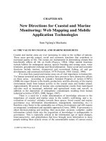
The groundwater unit used for the purposes of this study (the Triassic Sherwood
Sandstone) is located in the River Trent catchment of the Midlands region of
England, and comprises an easterly dipping sandstone aquifer bounded by a
Permian Magnesian Limestone aquifer to the west and confined by Triassic
mudstones to the east (Figure 6.1).
Figure 6.1 Map showing the location and extent of the unconfined Sherwood Sandstone aquifer unit
used for the digital water table interpolation.
The primary reasons for choosing the Sherwood Sandstone aquifer unit for the
study were: (i) the existence of a substantial data set of water level measurements
contained in the Environment Agency’s observation borehole network in the
Midlands region; and (ii) the availability of a reliable hand-contoured paper map of
© 2008 by Taylor & Francis Group, LLC
Digital water table mapping 103
the water table in the sandstone aquifer (scale 1:50,000; produced by ADAS
Cartography, Gloucester) which could be used to assess the accuracy of the
different interpolation methods. The hand-contoured map was based on data for a
high water level period obtained during January to April 1994.
The Sherwood Sandstone Group comprises undifferentiated sandstones that are
poorly cemented. The average hydraulic conductivity of the sandstones is 3.4 m
day
-1
and higher values are associated with locally-enhanced fissures induced by
coal workings which produce high groundwater yields of good quality
18
.
Approximately 42% of public water supplies in the area are from groundwater
supplied by the Sherwood Sandstone aquifer. The Sherwood Sandstone also
provides water for many major industries and is used to support irrigation of arable
crops in the area
16
. The surface topography is relatively flat over much of the area
and most groundwater recharge occurs through rain falling directly on to the
unconfined part of the aquifer in the west of the region. Annual effective rainfall
can be as low as 120 mm which, combined with a deep water table and relatively
high porosity of 30%, can lead to long delays in groundwater recharge
18
.
6.3 METHODS
6.3.1 Conversion of the Paper Map
For greater ease of comparison between the hand-contoured groundwater level
map representing the water table surface in early 1994 and the interpolated digital
maps, the paper map was converted into a digital layer in ArcView
®
GIS 3.2
(). This was achieved by superimposing the British National
Grid on to the paper map and recording the co-ordinates of points along each water
table contour. These co-ordinates and their respective depths were entered into a
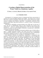
database and imported into ArcView GIS. The imported data were used to create a
triangulated irregular network (TIN) representing the water table, and the TIN was
converted to raster format at 50 m grid resolution (Figure 6.2a).
6.3.2 Data Point Selection
Data points from 59 locations were selected from a subset of 110 Environment
Agency observation boreholes in the Sherwood Sandstone aquifer (Figure 6.2b).
The study area boundary enclosed 82,500 ha of unconfined aquifer within the
sandstone unit and included three sites identified by the Environment Agency as
‘key borehole’ sites where water levels are not subject to major fluctuation or
influenced by local abstraction. These sites provide good quality data against
which the reliability of surrounding data points can be judged, thereby limiting the
amount of model input error. Hydrograph plots from each site in the entire subset
were examined and boreholes exhibiting irregularities in their plots, such as gaps in
the time series, or erratic fluctuations in water levels, were omitted from the
selection. Nine boreholes outside the study boundary, in the confined aquifer to the
© 2008 by Taylor & Francis Group, LLC
104 GIS for environmental decision-making
east, and five further sandstone boreholes located beyond the northern and southern
extremities of the study area boundary, were included in the selection so that the
subsequent water level interpolation would not suffer from ‘edge effects’. These
phenomena, manifested as a warping of the surface, can occur when there is an
absence of data beyond a boundary, resulting in unrealistically high or low values
19
.
Figure 6.2 (a) Digital representation of the hand-contoured water table in the unconfined area of the
Sherwood Sandstone aquifer. (b) Locations of the data points used for the water table interpolation.
Point A represents a peak water level value corresponding with an elevated water table surface in the
south-western corner of the study area.
6.3.3 Time Selection
To ensure consistency throughout the data set, water level data were compiled
from the selected borehole records using measurements taken for a single occasion
during a period of high rainfall in late 2001. All measurements fell within a three-
week period during the month of October, at which time the high water levels
represented minimum depth to the water table.
6.3.4 Data Interpolation
ArcView GIS was used to interpolate the water level data using spline and
inverse distance weighting (IDW) methods, and kriging interpolation of the same
data was executed in the GS+ program (Gamma Design Software,
). Although the area of interest was within the study
boundary, the three interpolated surfaces extended well beyond this boundary so
© 2008 by Taylor & Francis Group, LLC
Digital water table mapping 105
that differences between interpolation methods could be fully appraised. All three
interpolated surfaces were expressed in grid format, with a 50 m resolution.
Spline interpolation. The spline interpolation method applies local polynomial
functions to fit the smoothest possible surface through all data points, in a manner
in which a closest-fit curve might be plotted through points on a graph
20
. The
extent of smoothing relates to the number of points on which the polynomial curves
are based; the more points, the smoother the surface produced. The value of
weighting applied governs the curvature of the lines between individual data points
and has little effect in areas where data points are abundant, but increased
weighting leads to warping of the surface in areas where data points are sparse.
The spline surface that most closely matched the hand-contoured reference map
(Figure 6.2a) was achieved using a tension spline (which constrains the surface to
pass through all points) based on 6-point polynomials, with a 0.1 weighting.
IDW interpolation. Inverse distance weighting is an exact local interpolation
method that produces a surface whose value changes smoothly between the data
points to which it is tied. The data are inversely weighted so that calculated points
on the interpolated surface are more strongly influenced by nearby data points than
they are by more distant points
21
. The extent of smoothing of the surface is
dependent on the number of ‘nearest neighbors’ used for the interpolation, and on
the chosen value for the decay parameter, with the sphere of influence of a data
point diminishing more rapidly with higher decay values. The weight of the decay
parameter is expressed as a power function
20
.
In the current study, the IDW surface that most closely matched Figure 6.2a
was interpolated using 12 nearest neighbors and a value of 2 for the decay
parameter, giving an inverse weighting as the square of distance. This was found to
give the optimum sphere of influence to most data points, producing an acceptably
smooth surface without being unrealistic as to the extent to which any individual
point was affecting the interpolation.
Kriging interpolation. Kriging operates in a similar manner to IDW, but uses
the underlying spatial dependence of the data to calculate the most appropriate
value for the decay parameter. The spatial trend of the data is described by the
variogram
20,21
, which shows how data values vary with distance and direction. The
best-fitting variogram model can then be used to customize the kriging
interpolation by calculating appropriate weights according to clustering, distance
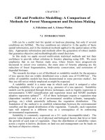
and direction of neighboring data points. In the current study, ordinary point
kriging, employing a spherical variogram model, was found to produce a surface
that most closely resembled the digital reference map (Figure 6.2a). The variogram
parameters and associated plot are given in Table 6.1 and Figure 6.3 respectively.
© 2008 by Taylor & Francis Group, LLC
106 GIS for environmental decision-making
Table 6.1. Kriging parameters relating to the water table interpolation
Model Parameter Value/Type
Active lag 24,000 m
Lag class interval 3000 m
Model Spherical
Nearest neighbors 12
Figure 6.3 Variogram plot for the kriging interpolation of the water table.
6.3.5 Evaluation of the Surfaces
Removal of peak value. One simple test for evaluating the effectiveness of an
interpolation method is to recalculate the surface after the removal of one or more
significant data points
22
. This test was performed on each of the interpolated
surfaces by removing a peak water level value (at Point A, Figure 6.2b)
corresponding with an elevated water table surface in the south-western corner of
the study area. The effects on the re-interpolated surfaces were examined for each
different method.
Cross-validation. Cross-validation analysis, which removes each data point in
turn and interpolates from the remaining points to estimate a value at the
corresponding location
23
, was performed on each of the three interpolated surfaces,
using the GS+ program for the IDW and kriged surfaces and ArcGIS
®
8
() for the spline surface.
Investigation of edge effects. These were examined by comparing an
interpolation that included 14 data points lying beyond the study area boundary
with one that excluded these points.
© 2008 by Taylor & Francis Group, LLC
Digital water table mapping 107
6.4 RESULTS
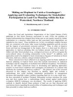
Representations of the three different water table interpolations are given in
Figure 6.4. All three surfaces exhibit a southwest to northeast decrease in water
table elevation within the study area boundary, from a minimum of 0 m, to a
maximum of 165 m above sea level. Point A represents a peak value in the
observed groundwater level data, which corresponds to elevated surface topography
in the southwestern corner of the study area. The main differences between the
interpolations are evident in the curvature of the contours in the northwest and
southeast corners of the map.
Figure 6.4 Representations of the water table in the Sherwood Sandstone aquifer, using (a) spline, (b)
IDW and (c) kriging interpolation methods. The location of the peak value, Point A, is shown.
The effects of removing the peak value Point A from each interpolation are
shown in Figure 6.5. Figure 6.5a indicates little change in the overall shape of the
spline surface, but Figures 6.5b and 6.5c show more significant local change in the
IDW and kriged surfaces, respectively. In the latter two surfaces, the ‘peak
contours’ are shifted eastwards, closely following the change in data distribution.
Results of cross-validation analyses of the three surfaces were expressed as
plots of estimated vs. observed values (Figure 6.6). The peak value Point A can be
seen as the major outlier in all plots. Regression analyses on these plots indicated
that the spline, IDW and kriged surfaces described 83%, 85% and 91%,
respectively, of the variability in the actual water table values.
© 2008 by Taylor & Francis Group, LLC
108 GIS for environmental decision-making
Figure 6.5 Maps showing the effect on the interpolated surfaces of removing the peak value, Point A,
from the data set: (a) the spline surface, (b) the IDW surface and (c) the kriged surface.
Figure 6.6 Cross-validation plots for (a) the spline surface, (b) the IDW surface and (c) the kriged
surface. The peak value, Point A, is the major outlier in all plots.
© 2008 by Taylor & Francis Group, LLC
Digital water table mapping 109
Figure 6.7 shows the effect of (a) including and (b) excluding data points
beyond the study boundary in the kriged interpolation. The greatest difference
relates to the curvature of contours in the southeastern quarter of the map, with
some lesser effects occurring around the southwestern peninsula of the study area.
Figure 6.7 Maps showing the kriged water table interpolation: (a) using 14 data points outside the study
area boundary, and (b) excluding these points.
6.5 DISCUSSION OF RESULTS
6.5.1 Visual Interpretation of the Surfaces
Although the spline interpolation method produces a credible surface in areas
where data are abundant and evenly distributed (Figure 6.4a), the global nature of
this method generates erratic values or warping of the surface where data are
sparse, as the method attempts to produce a smooth fit through all available data
points. Artifacts of this distortion are visible in the ‘pinching’ of the surface on
each side of the southern part of the aquifer, and most particularly in the southwest,
owing to the relative scarcity of data in this area.
The broadly similar surfaces produced by IDW and kriging (Figures 6.4b and
6.4c respectively) do not suffer from such effects. The close curvature of contours
around certain data points (Figure 6.4b) reflects the local nature of IDW
interpolation and shows the strong influence of data point values on the
immediately adjacent surface. The near-circular features around some data points
are not seen in the kriged surface (Figure 6.4c). Additionally, and in contrast to the
IDW interpolation, the contours of the kriged surface continue to diminish in value
towards the southeast corner of the map, taking the underlying spatial trend in
distance and value of neighboring data points into consideration.
© 2008 by Taylor & Francis Group, LLC
110 GIS for environmental decision-making
6.5.2 Removal of Peak Value
Comparison of Figure 6.4a with Figure 6.5a shows the very localised effect of
removing the single peak value Point A from the spline interpolation. The surface
values decrease in the immediate vicinity of the removed point, but the rest of the
surface remains unchanged.
The revised IDW interpolation (Figure 6.5b) shows significant local change of
surface shape in the vicinity of the removed point (compare with Figure 6.4b),
reflecting the eastward shift of the peak surface value. This leads to a greater area
of change adjacent to the southwest study boundary but, in common with the spline
surface, the rest of the interpolated area remains unchanged.
The eastward shift of the peak value in the kriged surface (compare Figure 6.4c
with Figure 6.5c) follows the local change in surface value, but does not exhibit the
intensely localized effect of the IDW surface. Removal of Point A produces more
widely distributed changes in the kriged interpolation, affecting the curvature of the
contours across the entire southern area of the map.
6.5.3 Cross-Validation
The cross-validation plots (Figure 6.6) indicate good correspondence between
estimated and actual water table values for all interpolation methods, with the
kriged interpolation achieving the best fit, as would be expected. However, the
value of the outlier Point A proved difficult to predict, resulting in underestimations
of 77 m, 72 m and 52 m, in the spline, IDW and kriged interpolations, respectively.
6.5.4 Examination of Edge Effects
The effect of excluding data points beyond the study boundary is best observed
in the results of two kriging interpolations (Figure 6.7). Exclusion of these points
led to a marked change in curvature of the kriging contours, not only in the
immediate vicinity of the excluded points, but also further afield, particularly in the
southern half of the map.
6.5.5 Comparison with Hand-Contoured Data
The hand-contoured map of the sandstone water table was produced seven years
prior to, and at a different time of year from the interpolated data, so direct
comparisons of absolute values cannot be made, although the general shape of the
interpolated and hand-contoured surfaces should be similar in the absence of major
changes in the groundwater abstraction regime. It should also be remembered that
the hand-contoured map is itself an approximation, the accuracy of which is not
known.
Taking these issues into consideration, it was decided to subtract the digital
representation of the hand-contoured surface from each of the interpolated surfaces,
in order to highlight areas where interpolation might be most problematic. The
© 2008 by Taylor & Francis Group, LLC
Digital water table mapping 111
resulting maps (Figure 6.8) indicated that the southern part of the aquifer was the
most difficult area to model successfully. In all three interpolations, most of the
estimated water table surface fell within one standard deviation of the hand-
contoured surface. The isolated pockets of greater deviation from the hand-
contoured map in the spline interpolation (Figure 6.8a) corresponded to the area
across which greatest ‘pinching’ was visible in Figure 6.4a, with the least
successful fit occurring near the southeastern corner. The IDW surface also
showed some disagreement in the southeastern corner, though to a lesser extent
than the spline surface, but produced a much less successful fit in the southwestern
peninsula (Figure 6.8b). Similarly, the kriged surface produced a poor fit in and
around the south-western peninsula (somewhat poorer than the IDW surface) and
had some minor areas of disagreement near the western and northwestern
boundaries.
Figure 6.8 Standard deviation maps showing the areas of difference between each of the interpolated
surfaces and the digital representation of the hand-contoured reference map: (a) the spline interpolation,
(b) the IDW interpolation and (c) the kriging interpolation.
The main discrepancies in each case appear to relate to spatial distribution of
the data. The northern part of the aquifer has a majority of fairly evenly distributed
boreholes on which to base the interpolations. Therefore, although there are minor
differences in the interpolated surfaces, all three methods appear to work equally
well. However, in the southern part of the map, data distribution is more irregular
with points clustered in the southeast corner, but fairly sparse in the southwest.
Furthermore, the peak outlier (Point A) occurs in an isolated area, close to the study
boundary, with few data points in the immediate vicinity.
© 2008 by Taylor & Francis Group, LLC
112 GIS for environmental decision-making
The close correspondence between the spline and hand-contoured surfaces in
the southwestern peninsula (Figure 6.8a) is likely to be coincidental, and due to the
warping of the spline surface just happening to follow the curvature of the actual
water table contours. The fit of the kriged surface (Figure 6.8c) in the southeastern
corner is better than that of the other two interpolations because of the more
accurate representation of the curvature of the contours beyond the study boundary.
6.5.6 Interpolation for Water Table Mapping Purposes
As seen in Figure 6.4a, the potential for edge effects and warping of the surface
when using spline interpolation makes this method unsuitable for modelling
surfaces with non-uniform distribution of data points, such as the location of
observation boreholes. A good approximation of actual surface values is achieved
where data points are abundant and evenly distributed, but warping of the surface
where data are sparse or irregularly spaced can give rise to unreliable values,
especially close to the boundary of the interpolated area.
IDW does not lead to such erratic surface values and boundary effects, and the
exact nature of this method gives a very accurate representation of the water table
in areas where data are abundant. Nevertheless, there is less certainty in the
interpolated surface where data are sparse, and circular features can arise from the
influence on the surrounding area of data point weighting.
The ability of kriging to accurately estimate and take account of the underlying
data trend leads to a closer approximation of the true surface in areas where data
are lacking. Of the three interpolation methods examined in this study, ordinary
point kriging is therefore thought to be the most suitable for water table mapping
purposes.
The change in surface shape afforded by inclusion of data beyond the confining
boundary indicates that interpolation should be extended beyond such boundaries to
avoid edge effects. In the Sherwood Sandstone study area, extra data points were
not available beyond the western boundary, which marks the western extent of the
sandstone aquifer. In such circumstances it may be appropriate to add some
‘dummy’ points beyond the study boundary, with values close to those of
neighboring data, to improve the surface representation near the boundary.
6.5.7 Derivation of the Final Depth to Water Table Map
As a final calculation, the kriged surface (Figure 6.4c) was subtracted from a
digital layer of surface topography (Ordnance Survey, Land-Form PANORAMA
™
digital terrain model, 50 m grid resolution) using the Map Calculator facility in
ArcView GIS. The resulting map of ‘depth to water table’ shown in Figure 6.9
clearly depicts channels indicative of groundwater in potential contact with the
topographic surface and, therefore, likely to represent groundwater discharge areas.
It was found that these channels corresponded closely with a digital overlay of the
major river network where groundwater discharge would be expected to occur.
© 2008 by Taylor & Francis Group, LLC
Digital water table mapping 113
Figure 6.9 ‘Depth to water table’ map for the unconfined area of the Sherwood Sandstone aquifer,
produced by subtracting the kriged water table surface from the topographic surface. The visible
channels, indicative of groundwater in potential contact with the topographic surface, correspond closely
with the major river network.
The magnitude of the negative values in Figure 6.9, interpreted to represent
surface flow caused by high artesian groundwater pressure, is rather high at a
number of locations, due to the absence of any constraint on surface water
elevations in the model. Additional analysis was therefore carried out which
involved including river elevation spot heights within the water level data set.
However, this did not entirely rectify the problem and also tended to distort the
interpolation of groundwater levels, since the potentiometric surface does not
necessarily follow surface water elevations. This approach to refining the
definition of depth to water table was therefore not taken any further.
6.6 CONCLUSIONS
This paper has discussed the issues involved in interpolating groundwater level
data and compared the outputs produced by three different methods (spline, IDW
and kriging). The results suggest that kriging generates the most reliable digital
© 2008 by Taylor & Francis Group, LLC
114 GIS for environmental decision-making
representation of the water table surface. The methodology presented here could be
applied in any region with adequate coverage of groundwater level monitoring
points and topographic data, to assist in groundwater management procedures and
vulnerability modelling.
6.7 ACKNOWLEDGMENTS
This study was conducted as part of a Natural Environment Research Council
PhD studentship (NER/S/A/2001/06/48), with CASE partner support from the
Environment Agency of England and Wales.
6.8 REFERENCES
1.
Hiscock, K.M., Hydrogeology: Principles and Practice, Blackwell Science Ltd, Oxford, 2005.
2.
Beeson, S. and Cook, M.C., Nitrate in groundwater: a water company perspective, Quarterly Journal
of Engineering Geology and Hydrogeology, 37, 261-270, 2004.
3.
Gooddy, D.C., Stuart, M.E., Lapworth, D.J., Chilton, P.J., Bishop, S., Cachandt, G., Knapp, M., and
Pearson, T., Pesticide pollution of the Triassic Sandstone aquifer of South Yorkshire, Quarterly Journal
of Engineering Geology and Hydrogeology, 38, 53-63, 2005.
4.
Silgram, M., Williams, A., Waring, R., Neumann, I., Hughes, A., Mansour, M., and Besien, T.,
Effectiveness of the Nitrate Sensitive Areas Scheme in reducing groundwater concentrations in England,
Quarterly Journal of Engineering Geology and Hydrogeology, 38, 117-127, 2005.
5.
Sokol, G., Leibundgut, C., Schulz, K.P., and Weinzierl, W., Mapping procedures for assessing
groundwater vulnerability to nitrate and pesticides, in: HydroGIS 93: Application of Geographic
Information Systems in Hydrology and Water Resources, Vienna. IAHS Publication No. 211, 1993, 631-
639.
6.
Hiscock, K.M., Lovett, A.A., Brainard, J.S., and Parfitt, J.P., Groundwater vulnerability assessment:
two case studies using GIS methodology, Quarterly Journal of Engineering Geology, 28, 179-194,
1995.
7.
Burkart, M.R. and Feher, J., Regional estimation of ground water vulnerability to nonpoint sources of
agricultural chemicals, Water Science and Technology, 33, 241-247, 1996.
8.
Lasserre, F., Razack, M., and Banton, O., A GIS-linked model for the assessment of nitrate
contamination in groundwater, Journal of Hydrology, 224, 81-90, 1999.
9.
Srivastava, P., Day, R.L., Robillard, P.D., and Hamlett, J.M., AnnGIS: Integration of GIS and a
continuous simulation model for non-point source pollution assessment, Transactions in GIS, 5, 221-
234, 2001.
10.
Lake, I.R., Lovett, A.A., Hiscock, K.M., Betson, M., Foley, A., Sünnenberg, G., Evers, S., and
Fletcher, S., Evaluating factors influencing groundwater vulnerability to nitrate pollution: developing the
potential of GIS, Journal of Environmental Management, 68, 315-328, 2003.
11.
Foster, D., Wood, A., and Griffiths, M., The Water Framework Directive (2000/60/EC) - an
introduction, Department of the Environment Northern Ireland (Environment & Heritage Service)
Workshop, Enniskillen, 2000.
© 2008 by Taylor & Francis Group, LLC
Digital water table mapping 115
12.
Harris, B., Groundwater management and protection in England and Wales - a backwards and
forwards glance, in Protecting Groundwater: Applying Policies and Decision Making Tools to Land-
Use Planning. Environment Agency NC/00/10/Conference Proceedings, Environment Agency, Bristol,
2001, 3-11.
13.
Rukin, N., Boland, M., and Thurston, N., Recommendations for an improved groundwater
vulnerability assessment framework, National Groundwater and Contaminated Land Centre, Report
NC/99/27, Environment Agency, Olton, 2003.
14.
Thapinta, A. and Hudak, P.F., Use of geographic information systems for assessing groundwater
pollution potential by pesticides in Central Thailand, Environment International, 29, 87-93, 2003.
15.
Holman, I.P., Dubus, I.G., Hollis, J.M., and Brown, C.D, Using a linked soil model emulator and
unsaturated zone leaching model to account for preferential flow when assessing the spatially distributed
risk of pesticide leaching to groundwater in England and Wales, The Science of the Total Environment,
318, 73-88, 2004.
16.
NRA, Policy and Practice for the Protection of Groundwater, National Rivers Authority, Bristol,
1992.
17.
Merchant, J.W., GIS-based groundwater pollution hazard assessment: a critical review of the
DRASTIC model, Photogrammetric Engineering & Remote Sensing, 60, 1117-1127, 1994.
18.
Edmunds, W. M. and Smedley, P. L., Residence time indicators in groundwater: the East Midlands
Triassic sandstone aquifer, Applied Geochemistry, 15, 737-752, 2000.
19.
Martin, D., Geographic Information Systems: Socioeconomic Applications, 2
nd
ed Routledge,
London, 1996.
20.
Webster, R. and Oliver, M.A., Geostatistics for Environmental Scientists, John Wiley & Sons, Ltd.,
Chichester, England, 2001.
21.
Isaaks, E.H. and Srivastava, R.M., An Introduction to Applied Geostatistics, Oxford University Press
Inc., New York, 1989.
22.
Burrough, P. A. and McDonnell, R. A., Principles of Geographical Information Systems, Oxford
University Press, Oxford, 1998.
23.
Todini, E., Influence of parameter estimation uncertainty in Kriging: Part 1 - Theoretical
development, Hydrology and Earth System Sciences, 5, 215-223, 2001.
© 2008 by Taylor & Francis Group, LLC