Software Solution for Engineers and Scientist Episode 2 pptx
Bạn đang xem bản rút gọn của tài liệu. Xem và tải ngay bản đầy đủ của tài liệu tại đây (392.64 KB, 90 trang )
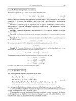
eration described above. In this opcode the right-most bit is moved into the carry
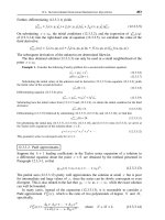
flag. Figure 3.2 shows the action of the 80x86 shift instructions.
The 80x86 opcodes for performing a bit shift to the left are SHL (shift logical
left) and SAL (shift arithmetic left). Notice that SHL and SAL are different mne
-
monics for the same operation (see Figure 3.2). In SHL and SAL it is the left-most
bit of the operand that is moved into the carry flag.
The terms logical and arithmetic, as used in the SHL and SAL opcodes, reflect a
potential problem associated with shifting bits in a signed representation. The
problem is that negative numbers in two’s complement form always have the high
bit set. Therefore, when the bits of a two’s complement number are shifted, the
sign bit can change unpredictably. For this reason, in left-shift operations of
signed operands the sign bit is moved into the carry flag. After performing the
shift, software can test the carry flag and make the necessary adjustments.
On the other hand, in a right-shift operation the sign bit is moved from bit num
-
ber 7 to bit number 6, and a zero bit is introduced into the sign bit position. This
action makes all signed numbers positive. In order to make possible shift opera-
tions of signed numbers the 80x86 instruction set has a separate opcode for the
right-shift of signed numbers. The SAR opcode (shift arithmetic right) preserves
the sign bit (bit number 7) while shifting all other bits to the right. This action can
be seen in the diagram for the SAR instruction in Figure 3.2. Note that, in the SAR
instruction, the left-most bit (sign bit) is both preserved and shifted. For example,
the value 10000000B becomes 11000000B after executing the SAR operation. This
action is sometimes called a sign extension operation.
Figure 3.2
80x86 Bit Shift Instructions
64
Chapter 3
76543210
76543210
76543210
76543210
76543210
76543210
0
0
CF
CF
CF
SHL - shift logical left
SAL - shift arithmetic left
SHR - shift logical right
SAR - shift arithmetic right
The 8-bit microprocessors that preceded the 80x86 family (such as the Intel 8080,
the Zilog Z80, and the Motorola 6502) did not include multiplication and division in
-
structions. In these chips multiplication and division had to be performed by soft
-
ware. One approach to multiplication was through repeated addition. Occasionally
this approach is still useful. The following code fragment illustrates multiplication
by repeated addition using 80x86 code.
; Multiplication of AL * CX using repeated addition
MOV AH,0 ; Clear register used to
; accumulate sum
MOV AL,10 ; Load multiplicand
MOV CX,6 ; Load multiplier
MULTIPLY:
ADD AH,AL ; Add AL to sum in AH
LOOP MULTIPLY
; AH now holds product of 10 * 6
An often-used method for performing fast multiplication and division operations
is by shifting the bits of the operand. This method is based on the positional proper
-
ties of the binary number system. In the binary number scheme the value of each
digit is a successive power of 2 (see Chapter 1). Therefore, by shifting all digits to
the left, the value 0001B (1 decimal) successively becomes 0010B (2 decimal), 0100B
(4 decimal), and 1000B (8 decimal).
A limitation of binary multiplication by means of bit shift operations is that the
multiplier must be a power of 2. If not, then the software must shift by a power of 2
that is smaller than the multiplier and add the multiplier as many times as necessary
to complete the product. For example, to multiply by 5 we can shift left twice and
add once the value of the multiplicand.
A more practical approach can be based on the same algorithm used in longhand
multiplication. For example, the multiplication of 00101101B (45 decimal) by
01101101B (109 decimal) can be expressed as a series of products and shifts, in the
following manner:
00101101B=45decimal
times 01101101B=109decimal
00101101
00000000
00101101
00101101
00000000
00101101
00101101
00000000
001001100101001B=4905 decimal
The actual calculations using this method of binary multiplication are quite sim
-
ple, since the product by a 0 digit is zero and the product by a 1 digit is the multipli
-
cand itself. The multiplication routine simply tests each digit in the multiplier. If the
Machine Arithmetic
65
digit is 1, the multiplicand is shifted left and added into an accumulator. If the
digit is 0, then the bits are shifted but the addition is skipped.
Shift-based multiplication routines were quite popular in processors that were
not equipped with a multiplication instruction. In the case of the 80x86 there
seems to be little use for multiplication routines based on bit shifts, since the pro
-
cessor is capable of performing efficient multiplications internally. For this rea
-
son, 80x86 programmers find little practical use for the SAR and SAL opcodes in
developing arithmetic routines, although these opcodes are still useful for other
bit manipulations.
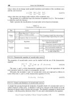
Bit Rotate Instructions
The 80x86 rotate instructions also shift the bits in the operand to the left or right.
The differencebetween theshift andthe rotateis thatin therotate thebit shiftedout
is either re-introduced at the other end of the operand or is stored in the carry flag.
The ROL opcode (rotate left) shifts the bits to the left while the high-order bit is cy
-
cled back to the low-order bit position, as well as stored in the carry flag. The ROR
opcode operates in a similar manner, except that the action takes place left-to-right.
In both instructions, ROL and ROR, the carry flag is used to store the recycled bit,
which can be conveniently tested by the software. Figure 3.3 shows the action of the
80x86 rotate instructions.
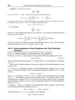
Figure 3.3 80x86 Bit Rotate Instructions
66
Chapter 3
76543210
76543210
76543210
76543210
76543210
76543210
76543210
76543210
CF
CF
CF
CF
ROL - rotate left
RCL - rotate through carry left
ROR - rotate right
RCR - rotate through carry right
Two rotate instructions, RCL (rotate through carry left) and RCR (rotate through
carry right), use the carry flag as a temporary storage for the bit that is shifted out.
This action can be seen in the diagrams of Figure 3.3. Note that the bit shifted out is
not recovered at the other end of the operand until the instruction is re-executed. It
is also interesting that by repeating the rotation as many times as there are bits in
the destination operand the rotate instructions preserve the original value. This re
-
quires rotating a byte-size operand 8 times, a word-size operand 16 times, and so on.
Double Precision Shift Instructions
The 386 introduced two new opcodes for performing bitwise operations on long bit
strings. These opcodes have the mnemonic SHLD (double precision shift left) and
SHRD (double precision shift right). The instructions are also available in the 486 and
the Pentium.
The double precision shift instructions SHLD and SHRD require 3 operands. For
example:
SHLD AX,BX,12
The left-most operand (AX) is the destination of the shift. The right-most operand
(12) is the bit count. The middle operand (BX) is the source. The bits in the source
operand are moved into the destination operand, starting with the sources’ high or-
der bits. Source and destination must be of the same size, for example, if the desti-
nation is a word-size register then the source has to be a word size register or
memory variable. By the same token, if the destination is a doubleword register or
memory location then the source must also be 32-bits wide. Either source or desti-
nation may be a memory operand, but at least one of them must be a machine regis-
ter. The count operand can be an immediate byte or the value in the CL register. The
limit of the shift count is 31 bits. The following code fragment shows a double preci
-
sion bit shift.
; Demonstration of the action preformed by the double precision
; shift left (SHLD)
MOV EAX,3456H ; One operand to destination
MOV EBX,10000000H ; Source operand
SHLD EAX,EBX,4 ; Shift left EAX digits 4 bits
; and introduce EBX bits into
; EAX bits vacated by the shift
; At this point:
; EAX = 34561
; EBX = 10000000 (unchanged)
The most common used of the SHLD and SHRD instructions is in manipulating
long bit strings. For example, you can overlay a memory variable with a register
value, as in the following code fragment using inline assembly:
int var1;
main()
{
_asm
{
MOV EBX,12300000H ; Source operand
Machine Arithmetic
67
SHLD var1,EBX,12
// ASSERT:
// VAR1 = 123H
}
}
In the above code fragments notice that the SHLD instruction has been used to
shift 4 packed BCD digits. The digit shift is accomplished by selecting a bit count
that is a multiple of 4, since each digit takes up 4 bits. In this manner a bit count of
8 would have shifted 2 packed BCD digits. Also notice that the source register is
unchanged by the double precision shift.
Shift and Rotate Addressing Modes
The addressing modes for shift and rotate opcodes have undergone several changes
in the different microprocessors of the 80x86 line. In the 8086 and 8088, shift and ro
-
tate can use a count in the CL register or the number 1 as an immediate operand.
Later processors allow an 8-bit immediate operand. The following code fragment il
-
lustrates the valid addressing modes in each case.
; Shift and rotate addressing modes in the 8086 and 8088 chips
SHL AL,1 ; Shift left 1 bit position
MOV CL,4 ; Shift count to CL
SHL AL,CL ; Shift left 5 bit positions
.
.
.
; Shift and rotate addressing modes in the 80286, 80386, 486,
; and Pentium, in which an 8-bit immediate operand can be specified
; directly
SHR AX,3 ; Shift right 3 bits
.
.
.
; In the 80386, 486, and Pentium the shift and rotate opcodes allow
; a 32-bit register operand as a destination, for example
SHL EBX,4 ; Shift EBX 4 bits
.
.
.
3.3.2 Comparison, Bit Scan, and Bit Test Instructions
The CMP (compare) instruction changes the flags as ifa subtractionhad takenplace
but does not change the value of the operands. The action can be described as set
-
ting the Status register as if the source operand had been subtracted from the desti
-
nation. The instruction is typically followed by a conditional jump. The following
code fragment shows the use of CMP in determining the relative value of an operand
in a machine register.
; Use of CMP to determine if BX > AX, BX < AX, or BX = AX
; Code assumes that the values in AX and BX are unsigned binary
CMP AX,BX ; Simulate AX minus BX
JA AX_ABOVE ; Go if AX > BX
JB AX_BELOW ; Go if AX < BX
; At this point AX = BX
.
68
Chapter 3
.
.
; Entry point for AX > BX
AX_ABOVE:
.
.
.
; Entry point for AX < BX
AX_BELOW:
.
.
.
The TEST instruction performs a logical AND and updates the flags without
changing the operands. If a TEST instruction is followed by JNZ, the jump is taken if
there are matching 1-bits in both operands. The following code fragment shows the
use of the TEST opcode.
; Use of TEST to determine if bit 7 of the AL register is set
TEST AL,10000000B ; ANDing AL and binary mask
JNZ HIGH_BIT_SET ; Go if AL bit7=1
; At this point AL bit7=0
.
.
.
; Entry point for AL bit 7 set
HIGH_BIT_SET:
.
.
.
The 80386 CPU introduced several new bit manipulating instructions that allow
more elaborate bit scanning and testing. The BSF (bit scan forward) opcode scans
the source operand low-to-high and stores, in the destination operand, the bit posi
-
tion of the first 1-bit found. If all bits of the source operand are 0, then the zero flag
is set, otherwise the zero flag is cleared. BSR (bit scan reverse) performs the same
test but starting at the high-order bit position. Both instructions require word or
doubleword operands; byte operands are not allowed. The following code fragment
shows the operation of BSF.
; Use of the BSF and BSR instructions to determine the number of
; the first bit set in the source operand.
MOV AX,10001000B ; Right-to-left first bit
; set is number 3
BSF BX,AX ; AX bit number into BX
; At this point BX = 03 since the first bit set is in bit
; position number 3 when read low-to-high. Zero flag is clear
BSR CX,AX ; AX bit number into CX
; read high-to-low
; At this point CX = 07 since bit number 7 of AX is the first
; bit set when read high-to-low. Zero flag is clear
The bit test opcodes BT (bit test), BTS (bit test and set), BTR (bit test and reset),
and BTC (bit test and complement) were also introduced with the 386 processor. All
of these opcodes copy the value of a specified bit into the carry flag. The code can
Machine Arithmetic
69
later include a JC or JNC instruction to direct execution according to the state of
the carry flag. In addition, the bit tested can be modified in the destination oper
-
and: BTS sets the tested bit, BTR clears the tested bit, and BTC complements the
tested bit. The following code fragment shows the action of these opcodes.
; Use of BT, BTS, BTR, and BTC opcodes to test and manipulate
; bits according to their position
MOV AX,10001000B ; Set value in operand
BT AX,3 ; Test AX bit 3
; Carry flag is set since AX bit 3 is set. AX is not changed
BTS AX,0 ; Test AX bit 0
; Carry flag is clear since AX bit 0 is not set
; AX = 10001001B since the instruction sets the specified bit
BTR AX,7 ; Test AX bit 7
; Carry flag is set since AX bit 7 is set
; AX = 00001001B since bit 7 is reset (cleared) by BTR
BTC AX,1 ; Test AX bit 1
; Carry flag is clear since bit 1 is cleared
; AX = 00001011B since bit 1 is toggled (complemented) by BTC
Signed and Unsigned Conditional Jumps
The 80x86 provides two categories of conditional jump opcodes: one for operating
on integers and one for operating on signed numbers in two’s complement form. For
example, JA (jump if above) and JB (jump if below) assume that the operands are
unsigned integers while JG (jump if greater) and JL (jump if less) assume that the
operands are signed numbers in two’s complement format. Table 3.2 shows the
80x86 conditional jump instructions according to their signed or unsigned interpre-
tation.
Notice in Table 3.2 that the conditional jump instructions that assume signed
operands use the sign and the overflow flag to determine their action. The sign
flag is clear when the result of the operation is a binary positive number, that is,
one in which the high bit is 0. The sign flag is set if the result of the previous oper
-
ation is a binary negative number, that is, one in which the high bit is set. On the
other hand, unsigned arithmetic routines usually ignore the sign flag since the
high-order bit of unsigned binary numbers is interpreted as value. The overflow
flag indicates a signed positive number that is too large to represent in the format,
or a signed negative number that is too small. In signed arithmetic this flag indi
-
cates an overflow, however, it is usually ignored when operating on unsigned bi
-
nary numbers.
Several jump instructions in Table 3.2 are based on the parity flag, namely: JNP
(jump if no parity), JPO (jump if parity odd), JP (jump if parity), and JPE (jump if
parity even). This flag is set if the low-order eight bits of the result contain an
even number of 1-bits (parity even) and cleared otherwise. This flag was provided
for compatibility with the Intel 8080 and 8005 processors. Although the parity flag
can be used to assure the integrity of data transmissions, it has no application in
arithmetic or logic routines.
70
Chapter 3
Table 3.2
x86 Conditional Jumps
MNEMONIC FLAG ACTION DESCRIPTION
CONDITIONAL JUMPS THAT ASSUME UNSIGNED OPERANDS
JA (CF or ZF) = 0 jump if above
JNBE jump if not below or equal
JAE CF = 0 jump if above or equal
JNB jump if not below
JNC jump if no carry
JB CF = 1 jump if below
JNAE jump if not above or equal
JC jump if carry set
JBE (CF or ZF) = 1 jump if below or equal
JNA jump if not above
JE ZF = 1 jump if equal
JZ jump if zero
JNE ZF = 0 jump if not equal
JNZ jump if not zero
JNP PF = 0 jump if no parity
JPO jump if parity odd
JP PF = 1 jump if parity
JPE jump if parity even
CONDITIONAL JUMPS THAT ASSUME SIGNED OPERANDS
JG ((SF xor OF) or ZF) = 0 jump if greater
JNLE jump if not less or equal
JGE (SF xor OF) = 0 jump if greater or equal
JNL jump if not less
JL (SF XOR OF) = 1 jump if less
JNGE jump if not greater or equal
JLE ((SF xor OF) or ZF) = 1 jump if less or equal
JNG jump if not greater
JNO OF = 0 jump if no overflow
JNS SF = 0 jump if positive (no sign)
JO OF = 1 jump if overflow
JS SF = 1 jump if negative (sign set)
Legend:
CF = carry flag ZF = zero flag PF = parity flag
SF = sign flag OF = overflow flag
3.3.3 Increment, Decrement, and Sign Extension Instructions
The INC (increment) instruction adds 1 to the value of the destination while the DEC
(decrement) instruction subtracts 1. INC and DEC are often used in manipulating
pointers although they find occasional application in arithmetic routines, mainly in
adjusting after overflow or underflow conditions. Both instructions assume that the
operand is an unsigned integer, therefore they do not affect the carry flag. For this rea
-
son, when operating with signed magnitudes it is preferable to use the ADD and SUB
instructions.
The 80x86 instruction set also includes several opcodes whose action is often de
-
scribed as performing a sign extension of the source operand. CBW (convert byte to
word) converts a signed byte in two’s complement form into a signed word, also in
Machine Arithmetic
71
two’s complement. The source is always the AL register and the destination is AX.
The conversion is performed by copying the most significant bit of AL into all AH
bits. Therefore the signed value 0083H is converted into FF83H, hence the use of
the term sign extension to describe its action. The opcode CWD (convert word to
doubleword) performs the same conversion regarding a word in AX to a
doubleword in DX:AX.
The 80386 processor introduced two new sign extension instructions designed
to operate on 32-bit and 64-bit operands. CWDE (convert word to doubleword ex
-
tended) converts a signed 16-bit number in AX into a signed 32-bit number in EAX.
The CDQ (convert doubleword to quadword) assumes a two’s complement num
-
ber in EAX and converts it into a signed 64-bit integer in EDX:EAX. The sign ex
-
tension opcodes are useful in performing signed multiplication and division when
one of the operands is in a different format than the destination. The following
code fragment is a demonstration of the use of the CBW instruction.
; Use of CBW to multiply a signed word operand in BX by a
; signed byte in AL
MOV BX,-1234 ; Load byte multiplier
MOV AL,-104 ; Load multiplicand (98H)
CBW ; Convert to word
; At this point AX holds FF98H (signed byte converted to word)
IMUL BX ; -1234 * -104
; Result of -1234 * -104 is 128,336. The product is stored
; in DX:AX as 0001:F550H
3.3.4 486 and Pentium Proprietary Instructions
The 486 and Pentium processors introduced 4 new instructions that are related to
arithmetic processing; these are: BSWAP (byte swap), XADD (exchange and add),
CHPXCHG (compare and exchange), and CMPXCHG8B (compare and exchange 8
bytes).
BSWAP
The BSWAP instruction reverses the byte order in a 32-bit machine register. One use
of BSWAP is in converting data between the little endian and the big endian formats.
In this sense it is possible to use BSWAP to reverse the order of unpacked decimal
digits loaded from a memory operand into a 32-bit machine register. For example:
assume four unpacked decimal digits are stored in a memory operand with the least
significant digit in the lowest order location, as would be the case in a conventional
BCD format. When these digits are loaded into a machine register by means of a
MOV instruction their order would be reversed. The following code simulates this
situation.
DATA SEGMENT
FOUR_DIGS DB 01H,02H,03H,04H
DATA ENDS
If these digits are now loaded into a 32-bit machine register, typically by means
of a pointer register, their order would be reversed, as shown in the following
fragment.
72
Chapter 3
LEA SI,FOUR_DIGITS ; Pointer to unpacked BCD
MOV EAX,DWORD PTR [SI] ; Load EAX using pointer
; EAX = 04030201H
At this point the unpacked BCD digits are reversed in the EAX register. In a
Pentium machine the situation can be easily corrected by means of the BSWAP in
-
struction. The instruction would reverse the bytes in EAX, as follows
BSWAP EAX ; Swap bytes in EAX
; EAX = 01020304H
Figure 3.4 shows the action of the BSWAP instruction.
Figure 3.4
Action of the 486 BSWAP Instruction
In a 386 CPU reversing the byte order in a 32-bit register requires several XCHG
(exchange) operations. The following procedure simulates the BSWAP in a 80386
machine.
BSWAP_EAX PROC NEAR
; Simulate the 486 BSWAP EAX instruction on a 386 machine
; Comments assume that on entry EAX = 0403 0201H
; After byte inversion EAX will hold 0102 0304H
;
PUSH EBX ; Save EBX in stack
MOV EBX,EAX ; Copy EAX in EBX
SHR EBX,16 ; Shift high word into low word
; At this point:
; EAX = 0403 0201H
; EBX = 0000 0403H
XCHG AH,AL ; EAX = 0403 0102H
SHL EAX,16 ; EAX = 0102 0000H
XCHG BH,BL ; EBX = 0000 0304H
OR EAX,EBX ; EAX = 0102 0304H
POP EBX ; Restore EBX
RET
BSWAP_EAX ENDP
XADD
The 486 XADD (exchange and add) instruction requires a source operand in a machine
register and a destination operand, which can be a register or a memory variable.
When XADD executes, the source operand is replaced with the destination and the
Machine Arithmetic
73
23 16
23 16
31 24
31 24
15 8
15 8
70
70
destination is replaced with the sum of both original operands. The main purpose of
this instruction is to provide a multiprocessor mechanism whereby several CPUs can
execute the same loop.
CMPXCHG and CMPXCHG8B
The 486/Pentium CMPXCHG (compare and exchange) opcode requires three
operands. The source must be a machine register. The destination can be either a ma
-
chine register or a memory variable. The third operand is the accumulator, which can
be either AL, AX, or EAX. If the value in the destination and the accumulator are equal
then CMPXCHG replaces the destination operand with the source. In this case the zero
flag (ZF) isset. Otherwise,the destinationoperand is loadedinto theaccumulator. In ei
-
ther casethe flags are set as ifthe destination operand had been subtracted from the ac
-
cumulator. Intel documentation states that CMPXCHG is primarily intended for
manipulating semaphores.
The Pentium processor includes a version of the compare and exchange opcode
with the mnemonic CMPXCHG8B (compare and exchange 8 bytes). Like CMPXCHG,
CMPXCHG8B requires three operands. The destination must be a memory variable.
The other two operands are a 64-bit (8 byte) value in EDX:EAX and a 64-bit value in
ECX:EBX. When the instruction executes the value in EDX:EAX is compared with
the destination operand. If they are equal, the value in ECX:EBX is then stored in the
destination. In this case the zero flag is set. If they are not equal then the destination
is loaded into EDX:EAX. In this case the zero flag is cleared. Intel documentation
states that CMPXCHG8B is also intended for manipulating semaphores.
3.4 CPU Identification
Software often needs to determine on which version of the CPU the program is running
in orderto useor bypassone ormore instructionsor to select among available features.
For example, previously we developed a procedure named BSWAP_EAX, which simu
-
lates the 486/Pentium BSWAP of the EAX register on a 386 machine. In order to develop
code that can execute in any machine environment it is possible to create several alter
-
native processing routes. A CPU test function can be called to determine which pro
-
cessing branch is required.
In later versions of the 486 CPU, Intel introduced an instruction named CPUID.
This instruction can be used to obtain information about the vendor, as well as the
CPU family, model, and stepping mode. The information returned by the instruction
depends on the value passed in the EAX register. If CPUID is executed with 0 in EAX,
then the instruction returns in EAX the highest input parameter that it can under
-
stand. For a Pentium family processor the smallest value returned in EAX is 1. Also
in this case the EBX, EDX and ECX registers may contain a string that identifies the
CPU vendor. If the Pentium is made by Intel Corporation, the string is “GenuineIntel.”
Other vendors may provide a different identification string.
If the CPUID instruction is executed with a value of 1 in EAX, then it returns addi
-
tional CPU information. Other values can also be loaded in EAX according to the
CPU processor family. Table 3.3 lists the values returned by several implementations
of the CPUID instruction.
74
Chapter 3
Table 3.3
Information Returned by CPUID Instruction
EAX
VALUE INFORMATION PROVIDED
0H EAX = maximum input understood by CPUID
EBX = “Genu” (756E6547H)
EDX = “ineI” (49656E69H)
ECX = “ntel” (6C65746EH)
1H EAX = version (type, family, model, and stepping ID)
EBX = brand index
EDX = feature information:
Bit: description
0 math unit on chip
1 Virtual 8086 mode enhancements
2 debugging extensions
3 page size extensions
… other information according to CPU version
2H EAX-EBX-ECX-EDX = cache and TLB information
3H ECX-EDX = Processor serial number
The following function, named IdCpu(), tests for five different CPU options used
in IBM microcomputers: 8086/8088, 80286, 80386, 486, and Pentium. If the CPU is a
Pentium then the CPUID instruction is executed with a value of 0 in EAX to test for
a ”GenuineIntel” signature. If the signature is “GenuineIntel” then the CPUID in-
struction is executed a second time with a value of 1 in EAX. When execution re-
turns to the caller the variables passed as an argument hold a CPU identification
code. If the processor was a Pentium made by Intel, then a second variable contains
the version information.
void IdCpu(int *CPUtype, int *Cid)
{
_asm
{
// Function to determine the CPU in a PC
// Post:
// Parameter CPUtype as follows:
// 1 if CPU is 8086 or 8088
// 2 if CPU is 80286
// 3 if CPU is 80386
// 4 if CPU is 486
// 5 if CPU is Pentium
// Parameter Cid contains the CPU identification code
// if processor id string is ‘GenuineIntel’
// Bits are as follows:
// xxxxxxxx xxxxxxxx xxxxxxxx xxxxxxxx <= bits
// |< ignored >| | | | |
// | | | |___[3-0] stepping ID
// | |____[7-4] model number
// |______[11-8] family
// Otherwise Cid is unchanged
;***********************|
; test for 8086/8088 |
;***********************|
Machine Arithmetic
75
; Bits 12 to 15 in the flag register are always set in the 8086
; and 8088 CPU
PUSHF ; Flag register to stack
POP AX ; Store flags in AX
AND AX,0FFFH ; Clear bits 12 to 15
PUSH AX ; AX to stack
POPF ; and to flags register
PUSHF ; Flags to stack
POP AX ; and to AX for reading
AND AX,0F000H ; Preserve bits 12 to 15
CMP AX,0F000H ; Test for bits set
JNE TEST_286 ; Go if bits not set
; At this point processor is a 8086 or 8088
MOV AX,1 ; Return code
MOV DX,0
JMP ID_EXIT ; Exit
;***********************|
; test for 80286 |
;***********************|
; Bits 12 to 15 in the flag register are always clear in the Intel
; 80286 CPU
TEST_286:
PUSHF ; Flag register to stack
POP BX ; Store flags in BX
OR BX,0F000H ; Make sure bit field is set
PUSH BX ; To stack
POPF ; And to flag register
PUSHF ; Flags to stack
POP AX ; And to AX
AND AX,0F000H ; Clear all other bits
JNZ TEST_386 ; Go if bits not clear
; At this point processor is an 80286
MOV AX,2 ; Return code
MOV DX,0
JMP ID_EXIT ; Exit
;***********************|
; test for 80386 |
;***********************|
; Bit 18 of the E flags register was introduced in the 486 CPU
; This bit cannot be set in the 80386
TEST_386:
PUSHFD ; 32-bits E flags to stack
POP EAX ; Flags to EAX
OR EAX,40000H ; Make sure bit 18 is set
PUSH EAX ; New flags to stack
POPFD ; An to E flags register
PUSHFD ; Back to stack
POP EAX ; And to EAX
AND EAX,40000H ; Clear all except bit 18
JNZ TEST_486 ; Go if bit 18 is clear
; At this point processor is a 80386
MOV AX,3 ; Return code
MOV DX,0
JMP ID_EXIT ; Exit
;***********************|
; test for 486 |
;***********************|
; Bit 21 (ID flag) of the E flags register cannot be set in the
; 486
TEST_486:
76
Chapter 3
PUSHFD ; 32-bits E flags to stack
POP EAX ; Flags to EAX
OR EAX,200000H ; Make sure bit 21 is set
PUSH EAX ; New flags to stack
POPFD ; An to E flags register
PUSHFD ; Back to stack
POP EAX ; And to EAX
AND EAX,200000H ; Clear all except bit 21
JNZ IS_PENTIUM ; Go if bit 21 is clear
; At this point processor is a 486
MOV EAX,4 ; Return code
MOV EDX,0
JMP ID_EXIT ; Exit
;***********************|
; processor is PENTIUM |
;***********************|
IS_PENTIUM:
;***********************|
; use CPUID |
;***********************|
MOV EAX,0
CPUID
CMP EBX,’uneG’
JE IS_INTEL
MOV EAX,5 ; Is Pentium type
JMP ID_EXIT ; but not Intel
IS_INTEL:
MOV EAX,1
CPUID
; At this point:
; EAX = contains the following information
// xxxxxxxx xxxxxxxx xxxxxxxx xxxxxxxx <= bits
// |< ignored >| | | | |
// | | | |___[3-0] stepping ID
// | |____[7-4] model number
// |______[11-8] family
;
MOV EDI,Cid
MOV [EDI],EAX
MOV EAX,5 ; Pentium code
ID_EXIT:
AND EAX,0FH ; Clear all other bits
MOV EDI,CPUtype
MOV [EDI],EAX
}
}
SOFTWARE ON-LINE
The Id CPU() function is found in the file Id CPU.h located in the folder Sample
Code\Chapter02\Id CPU in the book’s on-line software. The programId CPU.cpp,
also in this folder, calls the Id CPU() function and interprets the results.
Machine Arithmetic
77
Chapter 4
High-Precision Arithmetic
Chapter Summary
This chapter is about the algorithms and functions used in performing fundamental
arithmetic operations on packed BCD numbers. We develop C++ interface functions
for multi-digit BCD addition, subtraction, multiplication, and division. The chapter
concludes with the development of high-precision BCD-arithmetic functions that al-
low manipulating numbers with 34 significant digits.
4.0 Applications of BCD Arithmetic
The Intel mathematical coprocessor and math units are indeed powerful calculating
tools. These devices store and manipulate floating-point numbers according to the
formats defined in the ANSI/IEEE 754 standard. C and C++ use these standards in rep
-
resenting floating point numbers. The C/C++ float type corresponds to ANSI/IEEE sin
-
gle format and the C/C++ double type to ANSI/IEEE double format.
Table 2.2 shows that the significand in the ANSI/IEEE 754 double format is 53 bi
-
nary digits wide, to which we must add an implicit 1-bit. The largest decimal
significand allowed in 54 bits is 720,575,940,379,277,743, which makes it possible to
represent up to 18 significant digits. This precision is sufficient for many mathemati
-
cal applications; however, in science, business, and technology we occasionally
need to represent numbers of more than 18 significant digits. When this is the case,
the programmer must take on the task of encoding numeric values and performing
the necessary calculations.
One option for representing numeric values and performing calculations to
higher precision than ANSI/IEEE 754 is BCD arithmetic. The main disadvantages of
BCD arithmetic on the main CPU, compared to floating-point calculations using the
math unit, is that BCD code executes much slower and that encodings take up more
space. The one major advantage of developing BCD arithmetic routines is that the
precision of the calculations is not limited by the design of Intel floating-point hard
-
ware. Numeric operations on the floating-point units, such as the math unit of the
Pentium and the MMX, must be performed in the specific numeric data formats that
79
are built into the hardware. We have seen that, with present day floating-point
hardware, the maximum numeric precision of the result is of 18 significant digits.
The use of floating-point BCD arithmetic is an option when designing routines
that are capable of mathematical calculations to any desired precision.
Another consideration that, on occasions, favors the use of BCD arithmetic re
-
lates to round-off errors. The math unit is a binary machine and decimal numbers
must be converted to binary before processing. After the calculations have con
-
cluded, the results must be converted back to decimal numbers for output. The bi
-
nary-to-decimal and decimal-to-binary conversions often introduce errors, since
many decimal numbers cannot be exactly represented in binary. BCD arithmetic,
on the other hand, is decimal arithmetic. In BCD arithmetic no conversion errors
are introduced.
In developing the BCD arithmetic routines that are the topic of this chapter we
continue using the BCD12 format that was introduced in Chapter 2. However, the
BCD12 format is limited to numbers with 18 significant digits, which is approxi
-
mately the same precision of the Intel floating-point hardware. To make possible
high-precision BCD arithmetic we need a wider numeric format. At the end of the
chapter we present the BCD20 format, which allows representing numbers to 34
significant digits. The processing of BCD20 numbers is similar to that of BCD12;
therefore BCD20 routines are not listed in the text. These functions can be found
in the bcd20math.cpp module that is furnished in the book’s CD ROM.
4.0.1 ANSI/IEEE 854 Standard
On March 12, 1987, the Standards Board of the Institute of Electrical and Electronic
Engineers approved the IEEE Standard for Radix-Independent Floating-Point
Arithmetic. This project was sponsored by the Technical Committee on Micropro
-
cessors and Microcomputers of the IEEE Computer Society. The document was ap
-
proved by theAmerican NationalStandards Institute (ANSI)on September10, 1987.
It is stated in the Foreword that the purpose of this standard is “to generalize
ANSI/IEEE 754-1985 Standard for Binary Floating-Point Arithmetic, to remove de
-
pendencies on radix and word length.” ANSI/IEEE 854 applies to BCD arithmetic
as well as to binary, decimal, octal, or floating-point arithmetic in any other radix.
However, ANSI/IEEE 854 does not specify formats for floating-point numbers or
encodings of integers or strings representing decimal numbers. Therefore BCD
and ASCII formats, such as the BCD12 and BCD20, used in the examples in this
chapter, need not comply with any specific sizes or other requirements.
Furthermore, compliance or incompliance with the standard is not determined
at the level of the core routines, such as those developed in the remainder of this
chapter, but by how the results obtained from the core routines are handled by
the hardware and software. In other words, since compliance with ANSI/IEEE 854
is determined at the implementation level, no statement of compliance or
incompliance can be made about routines, procedures, sub-programs, or any com
-
ponent part of a software or hardware product.
80
Chapter 4
Notice that Standard 854 was directly derived from ANSI/IEEE 754, which makes
both standards quite similar.
4.1 Algorithms for BCD Arithmetic
Computer algorithms for multi-digit arithmetic on binary coded decimal numbers are
often derived from longhand methods. These are the traditional grade-school algo
-
rithms for longhand addition, subtraction, multiplication, and division. However, the
calculating routines can take advantage of certain facilities that are available in a digi
-
tal machine. In addition, the particular encoding used in representing the numerical
values can serve to facilitate or to hinder the actual calculations. Finally, the algo
-
rithms and routinesshould includeerror processing to identify illegalvalues, suchas a
zero divisor, and perform the necessary rounding operations on the results in order to
ensure accuracy. The following points apply to the BCD arithmetic routines presented
in this chapter:
1. The BCD arithmetic routines receive input in numbers coded and stored in float
-
ing-point BCD12 and BCD20 formats. This means that the processing algorithms are
based on the floating-point exponential representation used in the BCD12 and BCD20
encodings.
2. The routines calculate results to double the number of significand digits of the input
format, plus a possible carry. That is, the BCD12 routines calculate to 37 binary coded
decimal digits, and the BCD20 routines to 69 binary coded decimal digits. These re-
sults are rounded and returned in the BCD12or BCD20format ofthe operands,respec-
tively. Doubling the precision during calculations ensures that the significant digits of
the formats are maintained in multiplication and division.
3. While the BCD12 and BCD20 formats store digits in packed form, the arithmetic rou-
tines unpack these digits prior to performing numerical calculations. One reason for
this practice is that the Intel CPUs do not contain instructions for multiplication and
division of packed BCD operands. In order to maintain uniform processing all opera
-
tions are performed on unpacked digits.
4. The same rounding procedure is used by all BCD arithmetic routines. Rounding takes
place to the nearest even number.
5. Some functions use a common scratchpad area for temporary calculations and for vol
-
atile data. No effort was made at optimizing the use of this scratchpad space. Tempo
-
rary buffers and local variables were chosen to make the routines easy to develop and
understand, rather than to save a few bytes of memory.
6. The routines do not save the caller’s machine registers except for those used as point
-
ers to the passed data.
7. The exponents are stored as 4 packed BCD digits in both the BCD12 and BCD20 for
-
mats. The packed BCD exponent is converted to biased form during processing. This
conversion operation is performed by the function EXP_2_BIAS. Since the range of
the exponent in the BCD12 and the BCD20 formats is –9999 to +9999, the bias value of
10000 was chosen as a mid-range approximation. The convenience of a biased expo
-
nent in performing numerical calculations was discussed in Chapter 2.
High-Precision Arithmetic
81
8. The BCD arithmetic routines are compatible with all Intel 486 and Pentium CPUs
used in the PC.
9. The functions use a flat, 32-bit address space that is characteristic of the Win32 con
-
vention. The functions were developed using Visual C++ version 6.0 as Win32 con
-
sole applications. However, the source modules can also be used by Windows
programs.
10. All BCD arithmetic functions (add, subtract, multiply, and divide) take three param
-
eters in the respective BCD12 or BCD20 format. The first two parameters are the
operands, and the third one is used to return the result of the calculations.
The description of the functions, in the following sections, refer to the BCD12
format. The BCD20 format is described at the end of this chapter. For each func
-
tion in BCD12 arithmetic there is a corresponding one in BCD20.
4.2 Floating-Point BCD Addition
The function SignAddBcd12(), listed in Section 4.6, performs the signed addition of
two floating-pointnumbers encoded in BCD12 format. The processing assumes that
the BCD12 number has been normalized so that there are no leading zeros in the
significand, except for the encoding of the value 0. The implicit decimal point is lo-
cated between the first and second significand digits. The BCD12 encoding is de-
scribed in Chapter 2.
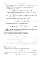
The algorithm for BCD addition is shown in the flowchart of Figure 4.1. The
logic for the operation z = x+y can be described as follows:
1. If the addends (x and y) have the samesign, thesignificands areadded andthe sumis
given the sign of the addends.
2. If the addends have unequal signs, the significand of the addend with the smaller ab
-
solute value is subtracted from the absolute value of the larger significand and the
result is given the sign of the addend with the larger absolute value.
3. The exponent of the sum is the exponent of the addend with the larger absolute
value. The operations performed on the significands may require adjusting the ex
-
ponent in order to maintain a normalized result.
The sum of the significands is rounded to 18 significant digits. If the difference
between exponents exceeds the final number of digits (18), then the addition of
the significands will not affect the result. This case, which is labeled the trivial
case, is illustrated in the code and is handled separately by the routine.
4.3 Floating-Point BCD Subtraction
The function named SignSubBcd12(), listed in Section 4.6, performs the signed sub
-
traction of two floating-point numbers encoded in BCD12 format. Algebraic sub
-
traction is performed by reversing the sign of the subtrahend and adding the
operands.
82
Chapter 4
Figure 4.1
Flowchart for Signed BCD Addition
4.4 Floating-Point BCD Multiplication
The function SignMulBcd12(), listed inSection 4.6,performs the signed multiplication
of two floating-point numbers encoded in BCD12 format. Processing assumes, as in
addition and subtraction, that the BCD12 encoding has been normalized so that there
are no leading zeros in the significand, except if the number is 0.
High-Precision Arithmetic
83
START
END
YES
YES
YES
YES
NO
NO
NO
NO
SUM IS NON-ZERO
ADDEND
EXPONENTS TO
BIASED FORM
OFFSET SMALLER
SIGNIFICAND
ENCODE SUM IN
BCD FORMAT
DETERMINE SIGN OF
NUMBER AND EXPONENT
STOREx<y
STOREx>y
STOREx=y
ADD
SIGNIFICANDS
SUBTRACT
SIGNIFICANDS
x<y
?
ADDENDS
HAVE SAME SIGN
?
x>y
?
x=0ORy=0
?
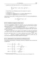
If the multiplication operation is represented asz=x· y then the algorithm
can be described as follows:
1. If one of the factors is zero (x or y) then the product is zero.
2. If the factors have equal signs the product is positive, if they have unequal signs the
product is negative.
3. The exponent of the product is the sum of the exponents of the multiplicand and the
multiplier.
4. The significand of the product is the significand of the multiplicand times the
significand of the multiplier.
5. The operations performed on the significands may require adjusting exponents in
order to maintain a normalized result.
Figure 4.2 is a flowchart of the processing performed by the SignMulBcd12()
function.
Figure 4.2
Flowchart for Signed BCD Multiplication
84
Chapter 4
START
END
YES
NO
SAVE ENTRY DATA AND
CLEAR BUFFERS
ENCODE PRODUCT IN
BCD FORMAT
DETERMINE SIGN OF
NUMBER AND EXPONENT
EXPONENTS TO BIASED FORM
ADD EXPONENTS
PRODUCT = 0
MULTIPLY SIGNIFICANDS
x=0ORy=0
?
4.5 Floating-Point BCD Division
The function SignDivBcd12(),listed inSection 4.6,performs the signed division oftwo
floating-point numbers encoded in BCD12 format. Here again, theprocessing assumes
that the BCD12 encoding has been normalized so that, in the representation of
non-zero values, there are no leading zeros in the significand.
Figure 4.3 is a flowchart of BCD division. If the division operation is in the form z
=x/y,then the algorithm can be described as follows:
Figure 4.3
Flowchart for Signed BCD Division
High-Precision Arithmetic
85
START
ERROR
END
YES
YES
NO
NO
SAVE ENTRY DATA AND
CLEAR BUFFERS
ENCODE PRODUCT IN
BCD FORMAT
DETERMINE SIGN OF
NUMBER AND EXPONENT
EXPONENTS TO BIASED FORM
SUBTRACT EXPONENTS
INVALID OPERATION
QUOTIENT = 0
DIVIDE SIGNIFICANDS
DIVISOR = 0
?
DIVIDEND = 0
?
1. If the dividend is zero (x = 0) the quotient is zero.
2. Division by zero is not defined, thereforea zerodivisor (y =0) is an invalidoperation.
In this case the first byte of the BCD result is set to FF hexadecimal. This special en
-
coding is detected by the BCD conversion routines and handled as an invalid oper
-
and.
3. If theelements x and y have equal signs, the quotient is positive. If they have unequal
signs, the quotient is negative. This rule for the sign of the result is the same as the
one used in the multiplication algorithm.
4. The exponent of the quotient is the difference between the exponent of the dividend
and the exponent of the divisor.
5. The significand of the quotient is the significand of the dividend divided by the
significand of the divisor.
6. The operations performed on the significands may require adjusting the exponents
in order to maintain a normalized result.
4.6 C++ BCD Arithmetic Functions
This section containsthe listingof theC++ functions forBCD arithmetic.Each func-
tion provides an interface with the low-level procedures that perform the actual cal-
culations. The following functions are listed:
1. SignAddBcd12() performs signed addition of two floating-point BCD numbers en-
coded in BCD12 format.
2. SignSubBcd12() performs signed subtraction of two floating-point BCD numbers
encoded in BCD12 format.
3. SignMulBcd12() performs signed multiplication of two floating-point BCD numbers
encoded in BCD12 format.
4. SignDivBcd12() performs signed division of two floating-point BCD numbers en
-
coded in BCD12 format.
//********************************************************************
// BCD12 arithmetic
//********************************************************************
void SignAddBcd12(char bcd1[], char bcd2[], char result[])
{
// Addition of two signed BCD numbers stored in BCD12 floating point
// format
// Operation:
// z=x+y
// where x, y, and z are signed, floating point numbers
// On entry:
// bcd1[] = Addend (element x inz=x+y)
// bcd2[] = Augend (element y inz=x+y)
// result[] is 12-byte storage area for result in BCD12 format
// Note: the code assumes that the BCD12 numbers are in normalized
// form, that is, that there are no leading zeros in the
// significand
// On exit:
// result = Sum (element z inz=x+y)
//
86
Chapter 4
// This routine operates on two numbers encoded in BCD12 format
// as follows:
//
// Sseeeem.mmmmmmmmmmmmmmmmmm
// |
// |____ implicit decimal point
//
// S = sign of number (1 BCD digit)
// s = sign of exponent (1 BCD digit)
// e = exponent (4 BCD digits)
// m = normalized significand (18 BCD digits)
// (first significand digit must be non-zero)
// . = implicit decimal point between the first and second
// significand digits
//*******************************************************************
//
// BCD signed addition algorithm:
// CASE 1:
// If x and y have the same sign, the absolute values are
// added and the result has the common sign
// CASE 2:
// If x and y have different signs, the smaller value is
// subtracted from the larger value and the result has the sign
// of the larger
//*******************************************************************
//
// Routine operations
// CASE 1 and 2:
// A. The input elements are tested for zero values. If one element
// is zero the result is the value of the other element
// B. The packed significands in BCD12 format are unpacked and moved
// into work buffers located in the code segment
// C. The unpacked significands are aligned in the work buffers SIG_L
// (for the significand of the number with the larger absolute
// value) and SIG_S (for the significand of the number with the
// smaller absolute value)
// CASE 1 (x and y have the same sign)
// SIG_R will hold the significand of the sum
// Addition operation:
// SIG_L = DDD DDD000000000000000
// + SIG_S = 0000ddd ddd00000000000
//
// SIG_R = Csssssssssssss00000000000
// legend:
// D = digits in the larger significand
// d = digits in the smaller significand
// s = digits in the sum
// C = possible carry digit in the sum significand
// (in this case the exponent must be adjusted)
//
// CASE 2 (x and y have different signs)
// SIG_R will hold the significand of the difference
// Subtraction operation:
// SIG_L = DDD DDD000000000000000
// - SIG_S = 0000ddd ddd00000000000
//
// SIG_R = Bsssssssssssss00000000000
// legend:
// B = possible borrow digit in the difference
// TRIVIAL CASE:
High-Precision Arithmetic
87
// If the difference between exponents is larger than the number
// of significand digits, then the aligned significands will be
// as follows:
// SIG_L = DDD DDD0000000000
// SIG_S = 0000000000ddd ddd
//
// SIG_R = 0DDD DDD0??? ???
// This means that the result (rounded to the format’s significand
// size) will equal the significand of the larger number. Therefore
// the addition or subtraction operation would be trivial
// D. The exponent of the sum is the exponent of the element with
// the larger absolute value, adjusted according to the operations
// performed on the significands
_asm
{
; Store entry variables
MOV ESI,bcd1
MOV EDI,bcd2
MOV EBX,result
CALL SIGN_ADD_BCD12
}
return;
}
void SignSubBcd12(char bcd1[], char bcd2[], char result[])
{
// Subtraction of two signed BCD numbers stored in BCD12 floating
// point format
// Operation:
// z=x-y
// where x, y, and z are signed, floating point numbers
// On entry:
// bcd1[] = Minuend (element x inz=x-y)
// bcd2[] = Subtrahend (element y inz=x-y)
// result[] is 12-byte storage area for difference (element z)
// Note: the code assumes that the BCD12 numbers are in normalized
// form, that is, that there are no leading zeros in the
// significand
// On exit:
// result[] = difference (element z inz=x-y)
// Operation:
// Processing is based on the algebraic principle of changing the
// sign of the subtrahend and proceeding as in addition
//
_asm
{
; Store entry variables
MOV ESI,bcd1
MOV EDI,bcd2
MOV EBX,result
CALL SIGN_SUB_BCD12
}
return;
}
void SignMulBcd12(char bcd1[], char bcd2[], char result[])
{
// Multiplication of two signed BCD numbers stored in BCD12 floating
88
Chapter 4