Software Solution for Engineers and Scientist Episode 6 pdf
Bạn đang xem bản rút gọn của tài liệu. Xem và tải ngay bản đầy đủ của tài liệu tại đây (1.05 MB, 90 trang )
oriented facilities. The enhancement ended up including classes, virtual functions,
a single line comment style, operator overloading, improved type-checking, multi
-
ple inheritance, template functions, and some degree of exception handling. The
C++ programming was standardized in 1998 as ISO/IEC 14882:1998. The current ver
-
sion dates from 2003.
During its evolution many libraries have been added to the C++ language. One
of the first ones was (named iostream) provided much needed stream-level input
and output functions. The new operators named cin() and cout() replaced the
more awkward C functions named printf() and scanf().
16.0.2 Advantages of the C++ Language
The following are the most often cited advantages of C language:
1. C++ is not a specialized programming language, therefore, it is suitable for develop
-
ing a wide range of applications, from major system program to minor utilities.
2. Although C++ is a relatively small language it contains all the necessary operators,
data types, and control structures to make it generally useful.
3. The language includes an abundant collection of library functions for dealing with
input/output, data and storage manipulations, system interface, and other primi-
tives not directly implemented in the language.
4. C++ data types and operators closely match the characteristics of the computer
hardware. This makes C++ programs efficient as well as easy to interface with as-
sembly language programs.
5. The C++ language is not tied to any particular environment or operating system. The
language is available on machines that range from microcomputers to mainframes.
For this reason, C++ programs are portable, that is, they are relatively easy to adapt
to other computer systems.
6. Object orientation is optional in C++. Applications that do not require object orien
-
tation can turn-off this feature.
16.0.3 Disadvantages of the C++ Language
The following are the most often noted disadvantages of C++:
1. Because C++ is not a language of very high level, it is not the easiest to learn. Begin
-
ners find that some constructions in C++ are complicated and difficult to grasp.
2. The rules of C++ language are not very strict and the compiler often permits consid
-
erable variations in the coding. This allows some laxity in style which often leads to
incorrect or inelegant programming habits.
3. Instead of being line C, a small and compact language, C++ has become large and
complex.
4. C++ library functions are devised to operate on a specific machine. This sometimes
complicates the conversion of C++ software to other implementations or systems.
5. The insecurities of C were not resolved in C++.
424
Chapter 16
16.1 PC Implementations of C and C++
Several software companies have developed C and C++ compilers for the PC. Some of
these products have gained and lost popular favor as other new versions or implemen
-
tations were introduced to the market. Historically some of the better known imple
-
mentations of C for the PC were the Microsoft C and Quick C compilers, IBM C 2
compiler (which is a version of Microsoft C licensed to IBM), Intel iC 86 and iC 286
compilers, Borland Turbo C, Turbo C Professional, Lattice C, Aztec C, Zortech C, and
Metaware High C.
Currently C++ development systems have almost completely replaced the old C
compilers. The most popular ones are the Microsoft versions furnished as part of
Developer’s Studio usually referred to as Visual C++. The last version of Visual C++
that did not include .NET support was version 6. After version 6, the .NET suffix was
added to C++ compiler versions, thus Visual C++ .NET in Developer’s Studio Ver
-
sion 7, Visual C++ .NET 2003 and Visual C++ .NET 2005. However, in the 2005 ver
-
sion the .NET designation was removed and there is a Visual C++ 2005 version.
Microsoft’s explanation for the name change is that the .NET designation had led
user’s to believe that the 7.0 and 7.1 compilers were intended exclusively for .NET
development, which is not the case.
Borland Corporation had developed and marketed several C++ systems for the
PC over the years. The current version is Borland C++ Builder 2006 for Microsoft
Windows. Two variations are available in the Borland product: the Professional and
the Enterprise editions.
16.2 Flowcharts and Software Design
A set of logical instructions designed to perform a specific task is called a program.
The document containing a set of instructions for starting a computer system could be
described as a power up program for a human operator. By the same token, a computer
program is a set of logical instructions that will make the computer perform a certain
and specific task. Note that in both cases the concept of a program requires a set of in
-
structions that follow a logical pattern and a predictable result. A set of haphazard in
-
structions that lead to no predictable end can hardly be considered a program.
Programmers have devised logical aids that help them make certain that com
-
puter programs follow an invariable sequence of options and their associated ac
-
tions. One of the most useful of these aids is called a flowchart. A flowchart is a
graphical representation of the options and actions that form a program. Flowcharts
use graphic symbols to enclose different types of program operations. The most
common ones are:
1. Rectangle. Used to represent processing operations such as arithmetic calculations
and data manipulations.
2. Parallelogram. Represents input and output functions, such as keyboard input, dis
-
play, and printing operations.
3. Diamond. Indicates a decision or logical comparison whose result is a yes or no.
The C++ Language on the PC
425
4. Circle. Used to represent a program termination point such as the end of execution
or an error exit.
5. Flow lines. Are used to connect other flowchart symbols indicating the direction of
program flow.
The use of a flowchart is best illustrated with an example. Figure 16.1 is a
flowchart of the program for turning on a computer system in which the compo
-
nents can be connected to the power line in three possible ways:
Figure 16.1
A Machine Start-Up Flowchart
1. All computer components are directly connected to individual wall outlets.
2. All computer components are connected to a power strip and the power strip is con
-
nected to the wall outlet.
3. Some components are connected to a power strip and some are connected directly
to the wall outlets.
Note in the flowchart of Figure 16.1 that the diamond flowchart symbols are
used to represent program decisions. These decisions correspond to the princi
-
ples of Aristotelian logic, therefore, there must be two and not more than two an
-
swers to the question. These possible answers are usually labeled YES and NO in
426
Chapter 16
START
END
YES
NO
NO
YES
Are all
components wired
individually
?
Are all
components wired
to power strip
?
Turn-on individual
component switches
Turn-on power strip
and individual
component switches
Turn-on power
strip switch
the flowchart. Decisions are the crucial points in the program’s logic. A program
that requires no decisions or comparisons consists of such simple logic that a
flowchart would be trivial and unnecessary. For instance, a flowchart that consists
of three processing steps: start, solve problem, and end, is logically meaningless.
Computing machines of the present generation are not equipped with humanlike
intelligence. Therefore some assumptions that are obvious when dealing with hu
-
man beings are invalid regarding computers. Computer programs can leave no loose
ends and make no assumptions of reasonable behavior. You cannot tell a computer
“well, you know what I mean.” The programmer uses flowcharts to make certain
that each processing step is clearly specified.
Regarding the flowchart graphics it should be noted that arrowheads are optional
in flowcharts if execution proceeds from the top down, as in Figure 16.1. However,
if execution flows up, to a higher flowchart level, then the connecting lines should
have arrowheads indicating the direction of program flow.
16.3 The C++ Console Application
Microsoft Visual C++ provides a text-based program type that is useful in developing
C++ programs that do not require a graphical user interface. For example, an engineer
requires a small program to perform a set of numerical calculations. If the application
is not to be distributed to other users and does not require graphics output, then the
console application provides a simple way of developing a C++ program.
To create a console application you must first start Visual C++ in Developer’s Stu-
dio. Once the development environment is displayed, select the New command in
the File menu. This command displays the selection box shown in Figure 16.2.
Figure 16.2
Visual C++ New File Command
The C++ Language on the PC
427
Once the New File box is displayed you must make sure that the Project tab is
active and select the Win32 Console Application option towards the bottom of the
Project Screen. Next you enter the name of your project and its location in the ma
-
chine’s file system. In this example we have named our project demo1. The button
to the right of the input box labeled “location:” allows browsing the machine’s file
system.
Once you click the OK button, the following screen contains several radio but
-
tons which allow selecting between an empty project, a simple application, a
“Hello, World” application, or an application that support MFC (Microsoft Foun
-
dation Classes). In this example we will select “A Simple Application” as shown in
Figure 16.3.
Figure 16.3
Selecting “A Simple Application” Option
Clicking the button labeled “Finish” produces a notification screen that
informs the user that a skeleton project has been created, its name, and the pres
-
ence of two precompiled headers named “Stdafx.h” and “StdAfx.cpp.” Figure 16.4
is a screen capture of this notification.
When you press the OK button execution returns to the main Visual Studio
screen. This screen is divided into three panes. The one on the right is the editor.
The one at the bottom shows development operations and is called the Build
pane. The pane at the left, called the Workspace pane shows the program compo
-
nents.
The Workspace pane now shows two buttons on its bottom margin. One, la
-
beled Class View, is currently selected. This mode of the Workspace pane is used
in object-oriented development. At this time you should click the button labeled
File View and then the plus sign (+) control to the left of the project files entry.
428
Chapter 16
This action will display the source, header, and resource files currently in the pro
-
ject. Also a ReamMe.txt file that contains information about the components of the
console application that you have just created.
Figure 16.4
Visual C++ New Project Information Screen
If you now expand the Source Files entry by clicking on its plus sign button a list
of two text files will be displayed. The first one, named demo.cpp (assuming that
you named your program “demo”) will be the source file created by Visual Studio.
You can use this file as a start point for your program. The file named StdAfc.cpp
contains a single statement to include stdafx.h with your source. You can view
stdafx.h by opening the Header Files group and double clicking the filename. Figure
16.5, on the following page, shows the Visual Studio screen at this point.
You should now edit the source file to suit your own programming style and start
coding the console application. The Build menu contains command to build the pro
-
gram (named Rebuild All) and to execute the code within the development environ
-
ment. For example, the following code listing shows a modification of the simple
application file into a Hello, World program.
The C++ Language on the PC
429
Figure 16.5
Visual C++ Screen for a New Project
// demo.cpp
// First demonstration program for a console application
// Coded by: Julio Sanchez
// Date: March 21, 2007 //
#include “stdafx.h”
#Include <iostream.h>
int main(){
cout < “\nHello World\n\n”;
return 0;
}
Notice that we have eliminated the parameters passed to the main() function
since our program does not use them. Also that we have added an include line for
the iostream library. This will allow us to use the powerful input and output func
-
tions in this library (cin() and cout()). When this program executes, a Hello,
World screen is displayed.
430
Chapter 16
Chapter 17
Event-Driven Programming
Chapter Summary
This chapter deals with the principles of Windows programming. In it we explain the
differences between a DOS and a Windows program and provide a model, called
event-driven programming, that is suitable for Windows applications. We also de-
scribe the fundamental components of a Windows program, its file structure, and vi-
sual features.
17.0 Graphical Operating Systems
The operating systems used in the first generation of digital computers required that
the user toggle a series of binary switches, each one with an attached light, in order to
enter data into the machine. In these systems, the bootstrap sequence consisted of a
predefined sequence of switch-toggling and button-pressing actions which the opera
-
tor memorized and executed in a ritual-like fashion. To handle one of these machines
you had to belong to a select class of binary-speaking, hexadecimal-minded experts
who devoted most of their life to deciphering the arcane mysteries of hardware and
software.
In the years that followed, several inventions and adaptations simplified com
-
puter input and output. IBM Corporation, that had developed punched cards for its
business machines, adapted this technology to its first line of computers. Teletype
machines (called TTYs) had been invented for use in the communications industry
but were soon adapted for use as computer devices. With the TTY, the typewriter
keyboard found its way into computing. Next came the use of Cathode Ray Tubes,
from commercial television, as a way of displaying text without having to print it on
paper. An added bonus was that the CRT could also be used to display pictures.
Other devices followed suit. Some have become standard elements of the tech
-
nology while others have disappeared. They include the lightpen, the touch screen,
the graphic tablet, the joystick, and the mouse. The common element in all of these
431
devices is that they allow the user to visually interact with the machine. The idea
for an interactive input device came from the work of Allan Kay at the Xerox Palo
Alto Research Center in the early 1970s. Dr. Kay was attempting to design a com
-
puter that could be used by preschool children, who were too young to read or to
type commands in text form. A possible approach was to use small screen objects,
called icons, that represented a familiar thing. A mechanical device (the mouse)
allowed moving these graphics objects on the screen in order to interact with the
system. Interactive graphics and the graphical user interface were the result.
Steve Wozniak, one of the founders of Apple computers, relates that he visited
Xerox PARC and saw the mouse and the graphical user interface. He immediately
concluded that the interactive way of controlling a computer was the way of the
future. Back at Apple, Wozniak started the development of an operating system
that supported graphical, mouse-controlled, icon-based, user interaction. After
one or two unsuccessful tries, the Macintosh computer was released. Soon there
-
after, Microsoft delivered a graphical operating system for the PC, called Win
-
dows.
17.1 Enter Windows
Many realized the advantages of a more reasonable and physical interaction with a
computing machine. However, it took many years for the actual implementation of
this idea in an effective operating system that would be preferred by the majority of
users. Douglas Engelbart demonstrated a viable mouse interface in 1968, but it took
fifteen years for the mouse to become a standard computer component. In order to
implement a graphical user interface (GUI) it was necessary to have not only a
pointing device that worked but also a graphics-capable video terminal. In addition,
the software would have to provide a set of graphics services in a device indepen-
dent manner.
In the PC world, the evolution of hardware and software components into a
graphical operating system took approximately one decade. The first versions
were rather crude and achieved little popular acceptance. It was not until Win
-
dows 95 that Microsoft’s graphical operating system for the PC became the stan
-
dard.
Originally, the development of a graphical operating system for the PC was a
joint effort between Microsoft and IBM. But soon, the two companies had major
strategic and tactical differences. IBM’s efforts resulted in a product called Oper
-
ating System/2, or OS/2. It seemed that Windows and OS/2 would share the PC op
-
erating system market. However, for reasons unrelated to its technical merits,
OS/2 quickly lost ground to Windows. OS/2 Warp version 4.0 was on the market
until 2005 but is no longer sold by IBM.
17.1.1 Text-Based and Graphical Programs
To a programmer, DOS and Windows are in different worlds. DOS programs have
complete and unrestricted access to the machine’s hardware. Once the code gains
control it can do whatever it pleases. Its only limitations are the hardware capabili
-
432
Chapter 17
ties and the programmer’s skills. Although the designers of DOS-like operating sys
-
tems often list rules that “well behaved programs” should follow, there is no way of
enforcing these rules. Intentionally or by error a DOS program can raise havoc with
the system by deleting files from storage and even attempting to physically destroy a
hardware device. Each DOS application has total control over all system resources. It
can allocate all memory to itself, set whatever video mode is convenient, control the
printer and the communications lines, and manage the mouse and the keyboard. Re
-
sources need not be shared since the operating system is dormant while an application
is in the foreground. In this environment, more than one application rarely execute si
-
multaneously.
Windows applications must share resources between themselves and with the op
-
erating system. Memory, CPU, display hardware, communications lines and devices,
mouse, keyboard, and disk storage are all shared. Each program operates in its pri
-
vate address space and has limited access to other memory areas. Code cannot ac
-
cess the hardware devices directly but must to do so through operating system
services called the Application Program Interface (API). This mechanism ensures
that all programs are well behaved.
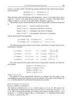
Windows and DOS graphics programming are quite different. Because all re-
source are shared, Windows must control access to all devices and resources, in-
cluding memory, the video system, communications devices, and input and output
components. Figure 17.1 shows how DOS and Windows programs access system re-
sources.
Figure 17.1
DOS and Windows Applications Access to System Resources
Event-Driven Programming
433
memory memory
disk storage disk storage
video system video system
I/O devices I/O devices
DOS
application
Windows
application
Windows
API
services
17.1.2 Graphics Services
Windows is a graphical operating system; therefore, a Windows application is a
graphics program. Since Windows applications use a graphical user interface, and
considering that an application’s access to resources must be controlled, then Win
-
dows is forced to provide a host of graphics services to applications. In a protected
mode environment, applications cannot access memory or devices directly. If an ap
-
plication attempts to do so, the CPU notifies the operating system (Windows in this
case) which proceeds first to halt and eventually to destroy the offending program.
The general rule under Windows is behave or you will be destroyed. The Windows
programmer has no direct control over the machine resources but the operating sys
-
tem provides services which allow supervised access.
17.2 Programming Models
The nature of the operating system environment determines the programming mod
-
els. In DOS, a program is “the god of the machine.” The running code has unre
-
stricted access and control. It executes on its own strengths, implements its own
functionality, and calls the operating system only to request a specific service. It
shares the machine with no other program. Therefore, the programming model for a
DOS program is a set of sequential instructions and program constructs. Control
does not return to the operating system until the application terminates. This form
of interaction between the application and the operating system gives rise to the se-
quential programming model.
The conceptual model for a Windows program is quite different. In this case,
the code has no direct access to devices and resources and must share the ma-
chine with other applications and with the operating system itself. The current
versions of Windows implement preemptive multitasking. This means that the op
-
erating system can switch the foreground (CPU access) from one application to
another. If an application misbehaves, Windows can simply turn it off. Therefore,
it is the operating system that is “the god of the machine,” not the running pro
-
gram.
17.2.1 Event-Driven Programs
A new programming model is necessary to accommodate this mode of interaction
between an application and the system code. The model is sometimes called
event-driven programming. In event-driven programming, synchronization be
-
tween the operating system and the application is in the form of program events. For
example, when the user changes the size of an application’s window (a user event),
the operating system takes the appropriate action and then notifies the application
code (a system event). The application, in turn, may decide to take its own action to
update its display area, or it may decide not to take any action at all. In either case, it
returns control to the operating system. The event-driven model, although simple
and effective, can appear odd to a programmer used to working in DOS. In the case
of a Windows program, the application’s code is no longer a sequential set of instruc
-
tions, but a series of blocks of code which execute when the corresponding message
is received.
434
Chapter 17
The event-driven model is implemented by means of messages passed among the
participants. In this example, we can say that in response to the user’s window
resizing event, the mouse device sent a message to the operating system, which in
turn, sent a message to the application. However, these messages are not like the in
-
terrupts so often used in DOS programming. DOS interrupts can run concurrently;
that is, a new interrupt can take place before the previous one has concluded. On
the other hand, Windows messages are queued and must wait in line until their turn
comes for processing.
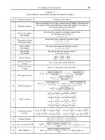
DOS programmers have to change their mindset when working in Windows. Fig
-
ure 17.2 shows two models of programming: the sequential model in a DOS program
and the event-driven model in a Windows programs. In DOS, the application re
-
ceives control at load time and retains it during its entire life span. In a Windows
program, a user input event sends a message to the operating system. The operating
system takes the appropriate action and sends a message to the corresponding ap
-
plication. The application looks at the message and decides if an action is required
or if the message should be ignored. In either case, it returns control to Windows. At
termination time, the application sends a message to Windows requesting to be
ended.
Figure 17.2
Sequential and Event-Driven Programming Models
Event-Driven Programming
435
DOS
(message)
(message)
DOS APPLICATION
WINDOWS APPLICATION
[event handlers]
USER INPUT EVENT
WINDOWS
OPERATING SYSTEM
[event manager]
// program code
initialize
get_user_input:
if action required
take action X
if program end
return to DOS
else
get_user_input
action X:
action (X=1)
get_user_input
action (X=2)
get_user_input
.
.
// end of program
// message processing
switch (msg)
case 1:
application event 1
return
case 2:
application event 2
return
.
.
default:
return
// send message
msg=end execution
return
The Event Manager
The principal difference between sequential and event-driven programs is that one
is active and the other one is passive. Event-driven code need not provide loops to
monitor user input since this function is performed by Windows. The application
stays dormant until it is notified by the operating system that an event has taken
place. It is the operating system code which must monitor the hardware devices in
order to detect actions which must be handled by the code. This function is called
event management, and Windows is the event manager.
It is the event manager’s responsibility to detect events and to make sure that
applications that must react to the events are promptly notified. This is usually
called an event dispatch operation. The event manager monitors hardware de
-
vices that can generate events, such as the keyboard and the mouse. The software
routine that checks for action on the event generating devices is sometimes called
the event loop.
The Event Handler
In the event-driven model, the application is the event handler. Its function is to wait
for an event to occur and then perform the corresponding action. The event handler
does not monitor event-generating devices directly, and often does not provide the
first level response to an event. It simply performs the action or actions that are
within its responsibilities and returns control to the event manager. In Windows all
of the complications of the device interface are performed at the system level. In
this sense, event-driven programs are easier to code since the “dirty work” is done
by the operating system.
17.2.2 Event Types
Events can be grouped into several types, although the classification is not very rig
-
orous. Often one event can be placed into one or another group according to our
own definitions. However, three general groups can be delimited without much
overlap:
•
System events
•
Control events
•
Program events
One event often triggers another one of the same or a different type. For exam
-
ple, a system-generated event can generate a control event. Or a program event
can be the cause of a system event, which, in turn, generates another system
event, and so forth. This interaction between events creates an event chain, and it
is this interconnection between related events that sometimes makes it difficult
to pinpoint a particular event type.
System Events
In this group are those events that originate in the operating system software. For
example, if the user presses the left mouse button while the cursor is inside the cli
-
ent area, Windows sends a WM_LBOTTONDOWN message to the application. This
436
Chapter 17
message indicates to the application code that a certain action has taken place (or is
about to take place) to which, perhaps, the program should respond. Many other sys
-
tem-generated events are possible, including a user typing on the keyboard, selecting
a menu item, moving the mouse cursor, dragging an object with the mouse, resizing a
window, or operating a scroll bar control.
Control Events
Control events relate to graphics control objects that are so abundant in the Windows
environment. Among them are buttons, list boxes, combo boxes, scroll bars, up-down
controls, and many others. A control event takes place when user interaction with a
control requires a reaction from the operating system or the application. In this case,
the control sent a message to the operating system. If necessary, the operating system
can then generate an event to notify the application of the user’s action.
Much of the programming required to implement a user interface consists of re
-
sponding to control events. The reason is that Windows programs have available
many standard controls. Programmers usually find it more convenient to use one of
these pre-canned components than to create a customized one. Windows controls
are discussed in greater detail later in this chapter.
Program Events
In Figure 17.1 we can see that the termination of a Windows application requires that
the program code send the corresponding message to the operating system. In this
case, the application originates an event in the form of a request to terminate execu-
tion. This type of event is called a programmer-created or program event.
17.2.3 Event Modeling
A program event is generated when the application code sends a message to the oper-
ating system requiring a service or action. However, program events are rarely at the
origin of the event chain. For example, the program event that requests program termi
-
nation often originates in a control event where the user indicated a desire to end the
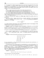
program. Figure 17.3, on the following page, shows the event chain that takes place
when a user clicks on the close button on a Window’s title bar.
In Figure 17.3 the message sent by the operating system to the application is la
-
beled WM_DESTROY. This is one of many standard messages that are used by Win
-
dows. The WM_DESTROY message indicates to an application that the operating
system has already destroyed the window. Therefore, the WM_DESTROY message is
received after the fact. Another Windows message named WM_CLOSE is sent to an
application to notify it that it is time to clean up and terminate. WM_CLOSE is a sort
of warning. This means that Figure 17.3 is actually a rough sketch of a process
which actually entails several other steps.
The Windows messaging system that results from event generation and handling
mechanisms can get quite complicated. The programmer or program designer often
needs to create a model of an event chain. Several modeling tools have been devel
-
oped for graphically depicting processes and data. Data flow and entity-relationship
diagrams are well-known tools used by program designers. However, these conven
-
Event-Driven Programming
437
tional tools are not well suited to modeling event-driven systems. Ward and Mellor
and also Hatley and Pribhai have introduced variations of the data flow diagrams
which are better suited for representing systems in which events take place in
real time. In Figure 17.3 we have used symbols from conventional data flow dia
-
grams and from the Ward and Mellor extensions in order to model an event chain.
More elaborate and detailed representations could include symbols for data
stores, control stores, and for processes.
Figure 17.3
An Event Chain
17.3 File Structure of a Windows Program
In addition to adopting an event-driven programming model in replacement of the
conventional sequential model, the Windows programmer also needs to become fa
-
miliar with the file structure of a Windows application. Many DOS programs have
simple file structures. In many cases, the only files external to the source arethevar
-
ious include files listed in the program header. Internally, the DOS compiler sets the
necessary linker options, references the corresponding libraries, and creates the
executable almost transparently to the programmer. Windows compilers are also
designed to automatically manage much of the complications of program genera
-
tion; however, Windows programs usually require more files than their DOS coun
-
terparts. Several of these files have no equivalent in DOS systems.
17.3.1 Source Files
The source files in Windows are of the same type as in DOS programming. In either
case, they contain the language statements and constructs ofaCorC++program.
Specific filename extensions are associated with different source files type, these
438
Chapter 17
msg. = close button down
msg. = WM_DESTROY
msg. = done!
control
event
system
event
program
event
closing window
terminate program
cleanup
are: .C, .CPP, and .H. The .C extension depicts a program in C. The presence of this ex
-
tension usually indicates that the program is coded in straight C; therefore, it does not
include any keywords and constructs that are part of C++. The .CPP extension indi
-
cates a source file that can contain C++-specific keywords and constructs. The .H ex
-
tension corresponds to a header file, usually referenced at the beginning of a program
by means of the #include statement.
17.3.2 Library Files
C and C++ are small languages: they do not provide functions for performing input and
output operations. For this reason, few useful programs in C or C++ contain no other
functions than those explicitly coded in the source. Most DOS programs, and virtually
all Windows programs, require the support of library functions.
Library files differ from source files. All the program files containing source code
are merged at compile time. Library functions are incorporated at link time, al
-
though the internal mechanisms of C and C++ development systems sometimes pre
-
vent us from noticing the difference. What often happens is that an #include
statement in a source file references a header file, which in turn, contains refer-
ences to other sources or to object code in a library. These references are usually
made by means of the extern declarator which serves to indicate that a variable or
function has external linkage. Figure 17.4 shows the different source, object, and li-
brary files that can be part ofaCorC++program.
Figure 17.4
File Structure of a Windows Program
Event-Driven Programming
439
VENDOR.H
VENDOR.OBJ
WINDOWS APPLICATION
DOS AND WINDOWS APPLICATIONS
WIN_LIB.DLL
USER2.CPP
USER1.CPP
USER.OBJ
MY_PROG.EXE
C or C++ COMPILER
LINKER
USER.H
VENDOR.LIB
USER.LIB
17.3.3 Resource Files
Windows programs have access to data items stored within the executable file, or in
a library file, called resources. Although resources are data, and though they are of
-
ten associated with the program’s .EXE file, they are unique. In the first place, re
-
sources cannot be modified at run time. They are actually read-only files and are not
directly accessible to program code. Furthermore, resources do not reside in the
program’s data area. At load time program resources are usually left on a disk file
until they are needed. Typical resources are icons, cursors, dialog boxes, menus,
bitmaps, and character strings.The current generation of software tools for devel
-
oping Windows applications, such as Microsoft Visual C++ and Borland C++, con
-
tain special tools for working with resources. In the Microsoft system there are
several specialized resource editors.
Resources, which have no equivalent in DOS programming, provide several ad
-
vantages to Windows applications:
•
User interface components are isolated from the rest of the code.
•
Applications can be modified without changing the resources.
•
Data can be shared among applications by reusing the same resources.
•
Graphical elements in the user interface can be created easily.
• Graphical elements in the user interface can be modified without changing the appli-
cation code.
Several special file types are used by Windows to manage resources. The re-
source script file (extension .RC) is an ASCII text file from which the binary re-
sources are created. Resource script files can be created manually by the
programmer or they can be automatically generated by the resource facilities in
the development environment. The Resource Compiler program, which is part of
the development system, produces binary resource files (extension .RES) from
the ASCII script files (extension .RC). In Microsoft Visual C++, the command line
version of the Resource Compiler is named RC.EXE; in Borland C++ it is named
BRCC.EXE or BRCC32.EXE.
Before Windows 95, the Resource Compiler also had the task of adding the bi
-
nary resources to the executable file created by the linker. The Microsoft linker
for Windows 95 and later versions can directly manipulate files in both .OBJ and
.RES formats.
17.3.4 Make Files
During the evolution of software development systems, the component programs
became increasingly more powerful. Consequently, the number switches, options,
and modes that could be selected in compilers, linkers and other tools also grew
rapidly. It became progressively more difficult for the programmer to remember
and enter all of these options every time that a project had to be compiled or up
-
dated. Various forms of so-called make programs and utilities were developed to
remedy this situation. By means of a make program the programmer would record
440
Chapter 17
all the switches and options in a text file and the make utility would automatically
apply them in a particular project.
In DOS programming, the simplest implementation of a make utility is a
batch file. An additional refinement is a program that reads the switches and
options selected in the development environment and applies them to the as
-
sembler, compiler, linker, or other software tools. In most environments, the
use of the make program is optional; however, in the Windows platform the op
-
tions and controls are so intricate that most programmers would not consider
entering them manually.
All major Windows C and C++ development systems for the PC have a make
utility. In Microsoft’s Visual C++, it is named NMAKE.EXE. In the Borland sys
-
tem, it is MAKE.EXE. The text file for either system has the extension .MAK.
Make files consist of instructions in ASCII text format. They can be created
manually or generated automatically by the development environment. The
make programs can be entered from the command line or they can be activated
from inside the development environment, usually by selecting a specific menu
option.
17.3.5 Object Files
The compiler program generates a file called an object file, which has the exten-
sion .OBJ. The Microsoft Visual C++ development system uses the Common Ob-
ject File Format (COFF) specification which originated in the UNIX operating
system. The Microsoft version of COFF adds additional header data in order to
make the format compatible with DOS and with 16-bit versions of Windows.
The compilers in Windows development systems have many different
switches, options, and modes of operation selectable by the user. In Visual C++,
the compiler options are selected through the Settings command of the Build
menu. The Project Settings dialog box contains a C/C++ tab which activates the
compiler switches and controls, as shown in Figure 17.5, on the following page.
Once the C/C++ tab is active in the Project Settings, a drop-down list box la
-
beled Category is displayed. When the Category box is expanded (see Figure
17.5), eight options appear. Selecting any one of these options activates a dialog
box with a new set of selectable choices. The Warning Level and Optimizations
drop down list boxes are also shown in Figure 17.5. The compiler warning level
determines the severity of warnings for which the compiler generates a mes
-
sage. Optimizations consist of four predefined modes: default, disable, maxi
-
mize speed, and minimize size. In addition, an entry labeled Customize (not
shown in Figure 17.5) is also in the list box. Selecting this option activates an
-
other list box of customized optimizations when the Optimizations options in
selected in the Category list box.
Mastering all the compiler options and switches requires considerable expe
-
rience with the development environment. Programmers often use the default
settings and make modifications to these settings when necessary.
Event-Driven Programming
441
Figure 17.5
Visual C++ the Compiler Options
17.3.6 Executable Files
In both DOS and Windows, the executable file is generated by a linker program. The
link command can be entered manually from the command line, through a batch file
or make program, or automatically by the development environment. The link oper
-
ation takes an object file generated by the compiler or assembler (extension .OBJ),
the library files generated by a library manager (extension .LIB), files in Common
Object File Format (extension .COFF), and the binary resource files created by the
resource compiler (extension .RES), and creates an executable file with the exten
-
sion .EXE. In addition, the Microsoft linker automatically converts 32-bit Object
Module Format (.OMF) files into COFF. The output of the linker can also be a dy
-
namic link library (extension .DLL).
The linker is the tool that generates the executable file; however, the Windows
development environments can activate the linker functions indirectly. In
442
Chapter 17
Microsoft Visual C++, the CL program can be used to compile source files, or to
compile and then link object files into executables. Make files can also reference the
linker operation. As in the case of the compiler, there are considerable numbers of
switches and options that can be selected at link time. In Visual C++, the linker op
-
tions are activated through the Settings command of the Build menu. The Project
Settings dialog box contains a Link tab, as shown in Figure 17.6.
Figure 17.6
Visual C++ Linker Options
When the Link tab is active in the Project Settings, a drop-down list box labeled
Category is displayed. Five options appear when the Category box is expanded (see
Figure 17.6). Selecting any one of these options activates a dialog box with a new set
of selectable choices.
Learning all the linker switches and options requires a mastery of the develop
-
ment system and as well as an intimate knowledge of the Windows operating sys
-
tem. Here again, programmers often change the default linker options only when
necessary, but this attitude often results in sacrifices in functionality and perfor
-
mance.
Event-Driven Programming
443
17.3.7 Dynamic Linking
One of the unique characteristics of Windows is dynamic linking. In DOS the linker
operates statically: it takes one or more object and library files and merges them
into an executable which physically includes all the code in both the sources and the
library modules. Windows programs use conventional libraries and source files at
link time, but also a special type of file called a dynamic-link library or DLL. In dy
-
namic linking, the library files are referenced at link time, but the code is not physi
-
cally incorporated into the executable. When the program runs, the required
run-time libraries are loaded into memory and the references are resolved.
Dynamic link libraries are binary files that have functions which can be shared
by several applications. In addition to sharing code between applications, DLLs
can be used to break up an application into separate components that are more
manageable and easier to upgrade. Dynamic linking has several advantages:
•
Several processes can share the same code thus saving memory space and reducing
access time.
•
DLLs can be modified and upgraded independently of the applications that use them.
Programs that use static libraries must be recompiled when the libraries are modi-
fied. This mechanism can be effectively used in providing after-sale support for a pro-
gram.
• DLLs can be accessed from different programming languages or environments as
long as the applications follows the calling conventions.
There are also disadvantages associated with DLLs. One of them is that the
code is not self-contained since it depends on the DLLs files being present on the
target system. If a process that uses load-time dynamic linking references a DLL
that is not available on the host machine, Windows immediately terminates the
program. In the case of applications that depend on run-time dynamic linking, the
program is not terminated if the DLL is not loaded, but the functionality associ
-
ated with the missing DLL are not available to the code.
Dynamic link libraries are stored in different formats and associated with vari
-
ous filename extensions. The standard extension is .DLL but files with the exten
-
sion .EXE, .DRV, .FON, and others can also perform as dynamic-link libraries. The
system-level DLL files, such as KERNEL32.DLL, USER32.DLL, and GDI32.DLL,
are found in the WINxx\SYSTEM directory. Files with the extension .DLL are
loaded automatically by Windows. Others must be explicitly loaded by the pro
-
gram module using the LoadLibary() or LoadLibaryEx() API functions.
In addition to DLLs, two other types of libraries and their associated files are
used in Windows programming:
•
Object libraries (extension .LIB) contain object code that is added to the application
at link time. Object libraries are used in static linking. The standard C libraries named
LIBC.LIB and LIBCMT.LIB are in this group.
•
Import libraries (extension .LIB) are a special form of an object library which con
-
tains no code. Import libraries provide information to the linker regarding dy
-
444
Chapter 17
namic-link libraries. Access to the dynamic link library GDI32.DLL is by means of the
import library named GDI32.LIB.
Event-Driven Programming
445
Chapter 18
The Window Program Components
Chapter Summary
Windows applications have unique characteristics. In this chapter we discuss some of
the more original features: Windows naming conventions, numeric constants, and
Windows handles. Windows programs are also visually different since a typical Win-
dows application has a graphics window and interactive controls. The chapter intro-
duces the use of these graphical components as well as elements of programming
style, such as program comments and assertions notation. Programming templates
are described as a means of simplifying the coding effort.
18.0 “Hello, World”
Experienced and talented DOS programmers are often intimidated by their first en-
counter with Windows programs. Windows programming has been described as
weird, convoluted, and awkward. In reality Windows programming is not more diffi
-
cult than DOS programming, although Windows programs, at first, appear more com
-
plicated.
In the first place, Windows text-only programs can be coded using the Console
Application facilities described in Chapter 16. Regarding programs that require
graphics or a Graphical User Interface, then Windows programs are definitively eas
-
ier to design and code than their DOS counterparts. Because Windows is a graphics
environment it contains a multitude of services, canned routines, and coding aids
that are not available in DOS. Anyone who has ever implemented a graphical user in
-
terface for a DOS application will greatly appreciate the graphics facilities in Win
-
dows.
Kernighan and Ritchie, in their book The C Programming Language, (published
by Prentice-Hall in 1978) listed the code for a short program that displays the mes
-
sage “hello, world!” on the screen. This program has since been known as the Hello
World program, and many other authors of programming books have followed suit.
The C++ version of the Hello World program is as follows:
447
#include <iostream.h>
void main() {
cout < “\nHello, World!”;
}
In a text-based operating system, such as DOS or UNIX, the Hello World pro
-
gram is quite simple. The message is displayed at the current position of the text
cursor, with whatever attributes are active. It assumes that the video system is a
“glass teletype” that scrolls automatically when the text reaches the end of the
screen. In this text-based paradigm there are no provisions for graphical user in
-
terface or for multitasking.
A Windows program that performs these same functions must deal with many
other levels of complexity. In the first place, it must coexist and share resources
with the operating system and with other applications. In Chapter 17 we dis
-
cussed the model of an event-driven program that is necessary in this case. In ad
-
dition, a Windows application is a graphics-based not a text-based program.
Finally, the program executes as a window which can be overlapped, overlaid,
minimized, maximized, to which keyboard and mouse input can be given or with
-
drawn, and many other functions. As can be expected, the code is more lengthy,
although it is relatively simple considering the functionality achieved. The follow-
ing is a listing for a Windows version of the Hello World program:
/********************************************************
WIN_HELLO.CPP Displays the message “Hello World from
Windows!" in the client area.
*********************************************************/
#include <windows.h>
LRESULT CALLBACK WndProc (HWND, UINT, WPARAM, LPARAM) ;
// WinMain()
int WINAPI WinMain (HINSTANCE hInstance, HINSTANCE
hPrevInstance, PSTR szCmdLine,
int iCmdShow)
{
static char szAppName[] = “WinHello” ;
HWND hwnd ;
MSG msg ;
// Defining a structure of type WNDCLASSEX
WNDCLASSEX wndclass ;
wndclass.cbSize = sizeof (wndclass) ;
wndclass.style = CS_HREDRAW | CS_VREDRAW ;
wndclass.lpfnWndProc = WndProc ;
wndclass.cbClsExtra = 0 ;
wndclass.cbWndExtra = 0 ;
wndclass.hInstance = hInstance ;
wndclass.hIcon = LoadIcon (NULL, IDI_APPLICATION) ;
wndclass.hCursor = LoadCursor (NULL, IDC_ARROW) ;
wndclass.hbrBackground = (HBRUSH) GetStockObject
(WHITE_BRUSH) ;
wndclass.lpszMenuName = NULL ;
wndclass.lpszClassName = szAppName ;
wndclass.hIconSm = LoadIcon (NULL, IDI_APPLICATION) ;
// Registering the structure wmdclass
RegisterClassEx (&wndclass) ;
// CreateWindow()
hwnd = CreateWindow (szAppName,
448
Chapter 18