Software Solution for Engineers and Scientist Episode 8 pptx
Bạn đang xem bản rút gọn của tài liệu. Xem và tải ngay bản đầy đủ của tài liệu tại đây (425.98 KB, 90 trang )
Device context operations belong to two types: those that obtain information
and those that set attributes. For example, the GDI function GetTextColor() re
-
trieves the current text color from the device context, while the function
SetTextColor() is used to change the text color attribute. Although these func
-
tions are sometimes referred to as get- and set-types, the function names do not
always start with these words. For example, the SelectObject() function is used to
both get and set the attributes of pens, brushes, fonts, and bitmaps.
Graphics applications often need to obtain information regarding the device
context. For example, a program may need to know the screen resolution or the
number of display colors. One of the most useful functions for obtaining informa
-
tion regarding the capabilities of a device context is GetDeviceCaps(). The call to
GetDeviceCaps() requires two parameters: the first one is the handle to the device
context, and the second one is an index value that identifies the capability being
queried. Table 23.1 lists some of the most useful information returned by this
function.
Table 23.1
Information Returned by GetDeviceCaps()
INDEX MEANING
DRIVERVERSION Version number of device driver.
TECHNOLOGY Any one of the following:
Value Meaning
DT_PLOTTER Vector plotter
DT_RASDISPLAY Raster display
DT_RASPRINTER Raster printer
DT_RASCAMERA Raster camera
DT_CHARSTREAM Character stream
DT_METAFILE Metafile
DT_DISPFILE Display file
HORZSIZE Width of the physical screen (millimeters).
VERTSIZE Height of the physical screen (millimeters).
HORZRES Width of the screen (pixels).
VERTRES Height of the screen (raster lines).
LOGPIXELSX Number of pixels per logical inch along the screen
width.
LOGPIXELSY Number of pixels per logical inch along the screen
height.
BITSPIXEL Number of color bits per pixel.
PLANES Number of color planes.
NUMBRUSHES Number of device-specific brushes.
NUMPENS Number of device-specific pens.
NUMFONTS Number of device-specific fonts.
NUMCOLORS Number of entries in the color table, if the
device has a color depth of no more than 8 bits
per pixel. Otherwise, –1 is returned.
ASPECTX Relative width of a device pixel used for line
drawing.
ASPECTY Relative height of a device pixel used for line
drawing.
ASPECTXY Diagonal width of the device pixel.
(continues)
604
Chapter 23
Table 23.1
Information Returned by GetDeviceCaps() (continued)
INDEX MEANING
CLIPCAPS Flag indicating clipping capabilities of the
device. Value is 1 if the device can clip to a
rectangle. Otherwise, it is 0.
SIZEPALETTE Number of entries in the system palette.
NUMRESERVED Number of reserved entries in the system palette.
COLORRES Actual color resolution of the device, in bits per
pixel.
PHYSICALWIDTH For printing devices: the width of the physical
page, in device units.
PHYSICALHEIGHT For printing devices: the height of the physical
page, in device units.
PHYSICALOFFSETX For printing devices: the distance from the left
edge of the physical page to the left edge of the
printable area, in device units.
PHYSICALOFFSETY For printing devices: the distance from the top
edge of the physical page to the top edge of the
printable area, in device units.
RASTERCAPS Value that indicates the raster capabilities of
the device, as follows:
Capability Meaning
RC_BANDING Requires banding support.
RC_BITBLT Capable of transferring bitmaps.
RC_BITMAP64 Supports bitmaps larger than
64K.
RC_DI_BITMAP Supports SetDIBits() and
GetDIBits functions.
RC_DIBTODEV Capable of supporting the
SetDIBitsToDevice function.
RC_FLOODFILL Capable of performing flood
fills.
RC_PALETTE Palette-based device.
RC_SCALING Capable of scaling.
RC_STRETCHBLT Capable of performing the
StretchBlt function.
RC_STRETCHDIB Capable of performing the
StretchDIBits function.
CURVECAPS Indicates the curve capabilities of the device,
as follows:
Value Meaning
CC_NONE Does not support curves.
CC_CIRCLES Device can draw circles.
CC_PIE Device can draw pie wedges.
CC_CHORD Device can draw chord arcs.
CC_ELLIPSES Device can draw ellipses.
CC_WIDE Device can draw wide borders.
CC_STYLED Device can draw styled borders.
CC_WIDESTYLED Device can draw wide and styled
borders.
CC_INTERIORS Device can draw interiors.
CC_ROUNDRECT Device can draw rounded
rectangles.
(continues)
Drawing Lines and Curves
605
Table 23.1
Information Returned by GetDeviceCaps() (continued)
INDEX MEANING
LINECAPS Indicates the line capabilities of the device, as
follows:
Value Meaning
LC_NONE Does not support lines.
LC_POLYLINE Device can draw a polyline.
LC_MARKER Device can draw a marker.
LC_POLYMARKER Device can draw multiple
markers.
LC_WIDE Device can draw wide lines.
LC_STYLED Device can draw styled lines.
LC_WIDESTYLED Device can draw lines that
are wide and styled.
LC_INTERIORS Device can draw interiors.
POLYGONALCAPS Indicates the polygon capabilities of the device,
as follows:
Value Meaning
PC_NONE Does not support polygons.
PC_POLYGON Device can draw alternate-fill
polygons.
PC_RECTANGLE Device can draw rectangles.
PC_WINDPOLYGON Device can draw winding-fill
polygons.
PC_SCANLINE Device can draw a single
scanline.
PC_WIDE Device can draw wide borders.
PC_STYLED Device can draw styled borders.
PC_WIDESTYLED Device can draw borders that
Are wide and styled.
PC_INTERIORS Device can draw interiors.
TEXTCAPS Indicates the text capabilities of the device, as
follows:
Value Meaning
TC_OP_CHARACTER Device is capable of character
output precision.
TC_OP_STROKE Device is capable of stroke
output precision.
TC_CP_STROKE Device is capable of stroke clip
precision.
TC_CR_90 Device is capable of 90-degree
character rotation.
TC_CR_ANY Device is capable of any
character rotation.
TC_SF_X_YINDEP Device can scale independently
in the x- and y-directions.
TC_SA_DOUBLE Device is capable of doubled
character for scaling.
TC_SA_INTEGER Device uses integer multiples
only for character scaling.
TC_SA_CONTIN Device uses any multiples for
exact character scaling.
(continues)
606
Chapter 23
Table 23.1
Information Returned by GetDeviceCaps() (continued)
VALUE MEANING
TC_EA_DOUBLE Device can draw double-weight
characters.
TC_IA_ABLE Device can italicize.
TC_UA_ABLE Device can underline.
TC_SO_ABLE Device can draw strikeouts.
TC_RA_ABLE Device can draw raster fonts.
TC_VA_ABLE Device can draw vector fonts.
TC_SCROLLBLT Device cannot scroll using a
bit-block transfer.
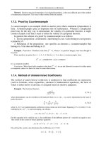
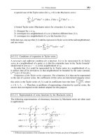
23.2.2 DC Info Demonstration Program
The program named DCI_DEMO, located in the DC Info Demo project folder on the
book's on-line software package, shows how to obtain device context information.
The menu labeled "DC Info" contains commands for displaying the most used general
device context capabilities, the device driver version, as well as the specific line and
curve drawing capabilities. Figure 23.1 shows the various menu commands in the
DCI_DEMO program.
Figure 23.1
Screen Snapshots of the DC Info Program
Drawing Lines and Curves
607
The Capabilities command in the DC Info menu displays the device context val
-
ues for some of the most used elements returned by the GetDeviceCaps() func
-
tion. To simplify the programming, the data required during processing is stored
in a header file named DC_Caps.h, which can be found in the project directory.
The header file is formatted as follows:
// Header file for DC Info Demo project
// Contains array of structures
#define LINES ((int) (sizeof DCcaps / sizeof DCcaps [0]))
struct
{
int iIndex ;
char *szLabel ;
char *szDesc ;
}
DCcaps [] =
{
HORZSIZE, "HORZSIZE", "Width (in mm):",
VERTSIZE, "VERTSIZE", "Height (in mm):",
HORZRES, "HORZRES", "Width (in pixels):",
.
.
.
NUMRESERVED, "NUMRESERVED", "Reserved palette entries:",
COLORRES, "COLORRES", "Actual color resolution:"
};
Each entry in the array of structures contains three elements. The first one (int
iIndex) is the index name required in the GetDeviceCaps() call. The two other ele-
ments are strings used at display time. Processing takes place in a loop in which
the number of iterations is determined by the constant LINES, which is calculated
by dividing the number of entries in the structure by the number of elements in
each entry. This coding allows us to change the number of entries in the array
without having to change the loop.
// Obtain and display DC capabilities
for(i=0;i<LINES ; i++) {
TextOut (hdc, cxChar, cyChar * (1 + i),
DCcaps[i].szLabel,
strlen (DCcaps[i].szLabel)) ;
TextOut (hdc, cxChar + 16 * cxCaps, cyChar * (1 + i),
DCcaps[i].szDesc,
strlen (DCcaps[i].szDesc)) ;
SetTextAlign (hdc, TA_RIGHT | TA_TOP) ;
TextOut (hdc, cxChar + 16 * cxCaps + 40 * cxChar,
cyChar * (1 + i), szBuffer,
wsprintf (szBuffer, "%5d",
GetDeviceCaps (hdc, DCcaps[i].iIndex))) ;
SetTextAlign (hdc, TA_LEFT | TA_TOP) ;
}
break;
In the previous code fragment, the first TextOut() call displays the szLabel vari
-
able in the DCcaps structure. The second call to TextOut() displays the szDesc
string. The value in the device context is obtained with the GetDeviceCaps() func
-
608
Chapter 23
tion that is part of the third call to TextOut(). In this case the iIndex element in the
array is used as the second parameter to the call. The wsprintf() function takes care
of converting and formatting the integer value returned by GetDeviceCaps() into a
displayable string.
Obtaining and displaying the driver version is much simpler. The coding is as fol
-
lows:
// Get driver version
_itoa(GetDeviceCaps(hdc, DRIVERVERSION),
szVersion + 16, 10);
// Initialize rectangle structure
SetRect (&textRect, // address of structure
2 * cxChar, // x for start
cyChar, // y for start
cxClient, // x for end
cyClient); // y for end
DrawText( hdc, szVersion, -1, &textRect,
DT_LEFT | DT_WORDBREAK);
break;
In this case we use the _itoa() function to convert the value returned by
GetDeviceCaps() into a string. SetRect() and DrawText() are then used to format
and display the string.
Obtaining and displaying the curve drawing and line drawing capabilities of the
device context requires different processing. These values (see Table 23.1) are re-
turned as bit flags associated with an index variable. For example, we make the call
to GetDeviceCaps() using the index constant CURVECAPS as the second parameter.
The integer returned by the call contains all the bit flags that start with the prefix CC
(CurveCaps) in Figure 23.1. Code can then use a bitwise AND to test for one or more
of curve drawing capabilities. The following code fragment shows one possible ap
-
proach for obtaining curve-drawing capabilities:
// Get curve drawing capabilities
curvecaps = GetDeviceCaps (hdc, CURVECAPS);
// Test individual bit flags and change default
// string if necessary
if (curvecaps & CC_NONE)
strncpy(szCurvCaps + 21, strNo, 3);
if (curvecaps & CC_CIRCLES)
strncpy(szCurvCaps + (26 + 21), strYes, 3);
.
.
.
if (curvecaps & CC_ROUNDRECT)
strncpy(szCurvCaps + (9 * 26 + 21), strYes, 3);
// Initialize rectangle structure
SetRect (&textRect, // address of
// structure
2 * cxChar, // x for start
cyChar, // y for start
cxClient, // x for end
cyClient); // y for end
DrawText( hdc, szCurvCaps, -1, &textRect,
Drawing Lines and Curves
609
DT_LEFT | DT_WORDBREAK);
break;
Each of the if statements in the processing routine tests one of the bit flags re
-
turned by GetDeviceCaps(). If the bit is set, then a text string containing the
words YES or NO is moved into the display string. When all the bits have been ex
-
amined, the message string named szCurvCaps is displayed in the conventional
manner.
23.2.3 Color in the Device Context
Monochrome displays are a thing of the past. Virtually all Windows machines have a
color display and most of themcango up to 16.7 million displayable colors. In graph
-
ics programming you will often have to investigate the color capabilities of a device
as well as select and manipulate colors.
In Windows programming, colors are defined by the relative intensity of the
red, green, and blue primary components. Each color value is encoded in 8 bits,
therefore, all three primary components require 24 bits. Since no C++ data type is
exactly 24 bits, however, the color value in Windows is stored in a type called
COLORREF, which contains 32 bits. The resulting encoding is said to be in RGB
format, where the letters stand for the red, green, and blue components, respec-
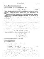
tively. Figure 23.2 shows the bit structure of the COLORREF type.
Figure 23.2
COLORREF Bitmap
Windows provides a macro named RGB, defined in the windows.h header file;
it simplifies entering the color values into a data variable of type COLORREF. The
macro takes care of inserting the zeros in bits 24 to 31, and in positioning each
color in its corresponding field. As the name RGB indicates, the first value corre
-
sponds to the red primary, the second one to the green, and the third one to the
blue. For example, to enter a middle-gray value, in which each of the primary col
-
ors is set to 128, proceed as follows:
COLORREF midGray; // Variable of type COLORREF
midGray = RGB(128, 128, 128);
The COLORREF data type is also used to encode palette colors. Windows uses
the high-order 8 bits to determine if a color value is in explicit RGB, palette-index,
or palette-relative format. If the high-order byte is zero, then the color is an ex
-
610
Chapter 23
31 24 23 16 15 8 7 0
FORMAT
CODE
RED
0 for explicit RGB format
1 for palette-index format
2 for palette-relative format
GREEN
BLUE
plicit RGB value; if it is 1 then it is a palette-index value; if it is 2 then the color is a
palette-relative value. Using the RGB macro when creating explicit-RGB values en
-
sures that the high-order byte is set correctly.
Obtaining color information from the device context requires careful consider
-
ation. Note in Table 23.1 that the index constant NUMCOLORS is valid only if the
color depth is no more than 8 bits per pixel. The device queried in Figure 23.1 has 16
bits per pixel; therefore, the NUMCOLORS value is set to –1. By the same token, the
COLORRES index constant is valid only if the device sets the RC_PALETTE bit. In
Figure 23.1 the value of this field is 0. The two most useful constants for obtaining
general color depth information are PLANES and BITPIXEL. PLANES returns the
number of color planes and BITPIXEL returns the number of bits used in encoding
each plane.
23.3 Graphic Objects and GDI Attributes
We should first mention that Windows graphics objects are not objects in the ob
-
ject-oriented sense. Windows graphics objects are pens, brushes, bitmaps, palettes,
fonts, paths, and regions. Of these, pens and brushes are the objects most directly re-
lated to pixel and line drawing operations.
23.3.1 Pens
The pen graphics object determines a line's color, width, and style. Windows uses the
pen currently selected in the device context with any of the pen-based drawing func-
tions. Three stock pens are defined: BLACK_PEN, WHITE_PEN, and NULL_PEN. The
default pen is BLACK_PEN, which draws solid black lines. Applications refer to a pen
by means of its handle, which is stored in a variable of type HPEN. The
GetStockObject() function is used to obtain a handle to one of the stock pens. The pen
must be selected into the device context before it is used, as follows:
HPEN aPen; // handle to pen
.
.
.
aPen = GetStockObject (WHITE_PEN);
SelectObject (hdc, aPen);
The two functions can be combined in a single statement, as follows:
SelectObject (hdc, GetStockObject (WHITE_PEN));
In this case, no pen handle variable is required. SelectObject() returns the handle
to the pen previously installed in the device context. This can be used to save the
original pen so that it can be restored later.
Drawing applications sometimes require one or more custom pens, which have a
particular style, width, and color. Custom pens can be created with the functions
CreatePen(), CreatePenIndirect(), and ExtCreatePen(). In the CreatePen() function
the pen's style, width, and color are passed as parameters. CreatePenIndirect() uses
a structure of type LOGPEN to hold the pen's style, width, and color.
ExtCreatePen(), introduced in Windows 95, is the more powerful of the three. The
Drawing Lines and Curves
611
iStyle parameter is a combination of pen type, styles, end cap style, and line join at
-
tributes. The constants used in defining this parameter are listed in Table 23.2.
Table 23.2
Values Defined for the ExtCreatePen() iStyle Parameter
PEN TYPE DESCRIPTION
PS_GEOMETRIC Pen is geometric.
PS_COSMETIC Pen is cosmetic. Same as those created with
CreatePen() and CreatePenIndirect(). Width
must be 1 pixel.
Pen Style
PS_ALTERNATE Windows NT: Pen sets every other pixel.
(cosmetic pens only.)
Windows 95: Not supported.
PS_SOLID Pen is solid.
PS_DASH Pen is dashed.
PS_DOT Pen is dotted.
PS_DASHDOT Pen has alternating dashes and dots.
PS_DASHDOTDOT Pen has alternating dashes and double dots.
PS_NULL Pen is invisible.
PS_USERSTYLE Windows NT: Pen uses a styling array supplied by
the user.
Windows 95: Not supported.
PS_INSIDEFRAME Pen is solid. Any drawing function that takes a
bounding rectangle, the dimensions of the figure
are shrunk so that it fits entirely in the
bounding rectangle. Geometric pens only.
End Cap Style (only in stroked paths)
PS_ENDCAP_ROUND End caps are round.
PS_ENDCAP_SQUARE End caps are square.
PS_ENDCAP_FLAT End caps are flat.
Join Style (only in stroked paths)
PS_JOIN_BEVEL Joins are beveled.
PS_JOIN_MITER Joins are mitered when they are within the current
limit set by the SetMiterLimit() function. If it
exceeds this limit, the join is beveled.
SetMiterLimit() is discussed in Chapter 21.
PS_JOIN_ROUND Joins are round.
The standard form of the ExtCreatePen() function is as follows:
HPEN ExtCreatePen (iStyle, // pen style
iWidth, // pen width
&aBrush, // pointer to a LOGBRUSH
// structure (next section)
dwStyleCount,// length of next parameter
lpStyle); // dot-dash pattern array
612
Chapter 23
The second parameter to ExtCreatePen() defines the pen's width. If the pen is a
geometric pen, then its width is specified in logical units. If it is a cosmetic pen
then the width must be set to 1.
A geometric pen created with ExtCreatePen() has brush-like attributes. The
third parameter is a pointer to LOGBRUSH. The LOGBRUSH structure, described
in the following section, is defined as follows:
struct tagLOGBRUSH {
UINT lbStyle;
COLORREF lbColor;
LONG lbHatch;
} LOGBRUSH
If the pen is a cosmetic pen, then the lbStyle member must be BS_SOLID and the
lbColor member defines the pen's color. In this case the lbHatch member, which
sets a brush's hatch pattern, is ignored. If the pen is geometric, then all three struc
-
ture members are meaningful and must be used to specify the corresponding at
-
tributes.
The fourth parameter, dwStyleCount, determines the length of the fifth parame-
ter. The fifth parameter, lpStyle, is a pointer to an array of doubleword values. The
first value in the array is the length of the first dash of a user-defined pen style, the
second one is the length of the first space, and so on. If the pen style does not con-
tain the PS_USERSTYLE constant, then the fourth parameter must be zero, and the
fifth parameter must be NULL. Note that PS_USERSTYLE is supported in Windows
NT but not in Windows 95 or later versions.
The end cap styles determine the appearance of the line ends. Three constants
are defined for round, square, and flat line ends. The end join style determines the
appearance of the connecting point of two lines. Both styles are available only for
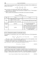
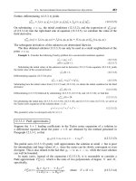
geometric pens. Figure 23.3, on the following page, shows the pen styles and the
effects of the different end caps and joins.
Note in Figure 23.3 that the difference between square and flat caps is that the
square style extends the line by one-half its width. The white lines in the end cap style
insert are drawn with the white stock pen, to better show the style's effect. The
NULL_PEN style creates a pen that draws with transparent ink, therefore it leaves no
mark as it moves on the drawing surface. This style is occasionally used in creating
figures that are filled with a particular brush style but have no border.
23.3.2 Brushes
The brush object determines the attributes used in filling a solid figure. The outline of
these figures is determined by the brush selected in the device context. A brush has a
style, color, and hatch pattern. There are several stock brushes: WHITE_BRUSH,
LTGRAY_BRUSH, GRAY_BRUSH, DKGRAY_BRUSH, BLACK_BRUSH, and
NULL_BRUSH. All stock brushes are solid, that is, they fill the entire enclosed area of
the figure. The NULL_BRUSH is used to draw figures without filling the interior. If a
solid figure is drawn with the NULL_PEN, then it is filled but has no outline.
Drawing Lines and Curves
613
Figure 23.3
Pen Syles, End Caps, and Joins
Applications refer to a brush by its handle, which is stored in a variable of type
HBRUSH. The GetStockObject() function is used to obtain a handle to one of the
stock brushes. The brush must be selected into the device context before use, as fol-
lows:
HBRUSH aBrush; // handle to brush
.
.
.
aBrush = GetStockObject (WHITE_BRUSH);
SelectObject (hdc, aBrush);
As in the case of a pen, the two functions can be combined in a single statement,
as follows:
SelectObject (hdc, GetStockObject (WHITE_BRUSH));
In this case, no brush handle variable is required. SelectObject() returns the han
-
dle to the brush previously installed in the device context. This can be used to save
the original brush so that it can later be restored.
A custom brush is created by means of the CreateBrushIndirect() function. The
call returns a handle to the brush, of type HBRUSH. The only parameter is a pointer
to a structure of type LOGBRUSH which holds the brush style, color, and hatch pat
-
tern. The LOGBRUSH structure is also used by the ExtCreatePen() previously de
-
scribed. Table 23.3 lists the predefined constants used for members of the
LOGBRUSH structure.
614
Chapter 23
PS_SOLID
PS_DASH
PS_DOT
PS_DASHDOT
PS_DASHDOTDOT
PS_INSIDEFRAME
PS_NULL
PS_SOLID
PS_INSIDEFRAME
PS_ENDCAP_ROUND
PS_JOIN_BEVEL
PS_ENDCAP_SQUARE
PS_JOIN_MITER
PS_ENDCAP_FLAT
PS_JOIN_ROUND
Pen Styles:
End Cap Styles:
Line Join Styles:
The foreground mix mode attribute of the device context, also called the drawing
mode, determines how Windows combines the pen or brush color with the display sur
-
face when performing drawing operations. The mixing is a raster operation based on a
boolean function of two variables: the pen and the background. For this reason it is de
-
scribed as a binary raster operation, or ROP2. All four boolean primitives are used in
setting the mix mode: AND, OR, NOT, and XOR. The function for setting the foreground
mix mode is SetROP2(). GetROP2() returns the current mix mode in the device con
-
text. The general form of the SetROP2() function is as follows:
Table 23.3
Constants in the LOGBRUSH Structure Members
BRUSH STYLE DESCRIPTION
BS_DIBPATTERN A pattern brush defined by a device-independent
bitmap. If lbStyle is BS_DIBPATTERN, the lbHatch
member contains a handle to a packed DIB.
Note: DIB stands for Device Independent Bitmap.
DIBs were discussed previously.
BS_DIBPATTERNPT Same as BS_DIBPATTERN but the lbHatch member
contains a pointer to a packed DIB.
BS_HATCHED Hatched brush.
BS_HOLLOW Hollow brush.
BS_NULL Same as BS_HOLLOW.
BS_PATTERN Pattern brush defined by a memory bitmap.
BS_SOLID Solid brush.
BRUSH COLOR DESCRIPTION
DIB_PAL_COLORS The color table consists of an array of 16-bit
indices into the currently realized logical
palette.
DIB_RGB_COLORS The color table contains literal RGB values.
HATCH STYLE DESCRIPTION
HS_BDIAGONAL A 45-degree upward, left-to-right hatch.
HS_CROSS Horizontal and vertical cross-hatch.
HS_DIAGCROSS 45-degree crosshatch.
HS_FDIAGONAL A 45-degree downward, left-to-right hatch.
HS_HORIZONTAL Horizontal hatch.
HS_VERTICAL Vertical hatch.
int SetROP2(
HDC hdc, // 1
int fnDrawMode // 2
);
23.3.3 Foreground Mix Mode
The first parameter is the handle to the device context and the second parameter is
one of sixteen mix modes defined by Windows. The function returns the previous mix
mode, which can be used to restore the original condition. Table 23.4 lists the ROP2
mix modes. The center column shows how the pen (P) and the screen (S) pixels are
logically combined at draw time. The boolean operators correspond to the symbols
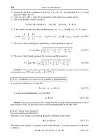
used in C. Figure 23.4, on the following page, shows the brush hatch patterns.
Drawing Lines and Curves
615
Table 23.4
Mix Modes in SetROP2()
BOOLEAN
CONSTANT OPERATION DESCRIPTION
R2_BLACK 0 Pixel is always 0.
R2_COPYPEN P Pixel is the pen color. This is the
default mix mode.
R2_MASKNOTPEN ~P&S Pixel is a combination of the colors
common to both the screen and the
inverse of the pen.
R2_MASKPEN P&S Pixel is a combination of the colors
common to both the pen and the
screen.
R2_MASKPENNOT P&~S Pixel is a combination of the colors
common to both the pen and the
inverse of the screen.
R2_MERGENOTPEN ~P|S Pixel is a combination of the screen
color and the inverse of the pen color.
R2_MERGEPEN P|S Pixel is a combination of the pen color
and the screen color.
R2_MERGEPENNOT P|~S Pixel is a combination of the pen color
and the inverse of the screen color.
R2_NOP S Pixel remains unchanged.
R2_NOT ~S Pixel is the inverse of the screen
color.
R2_NOTCOPYPEN ~P Pixel is the inverse of the pen color.
R2_NOTMASKPEN ~(P&S) Pixel is the inverse of the color.
R2_MASKPEN Pixel is color of mask.
R2_NOTMERGEPEN ~(P|S) Pixel is the inverse of the _MERGEPEN
color.
R2_NOTXORPEN ~(P^S) Pixel is the inverse of the R2_XORPEN
color.
R2_WHITE 1 Pixel is always 1.
R2_XORPEN P^S Pixel is a combination of the colors in
the pen and in the screen, but not in
Both.
Legend:
~ = boolean NOT | = boolean OR
& = boolean AND ^ = boolean XOR
Figure 23.4
Brush Hatch Patterns
616
Chapter 23
HS_VERICAL
HS_HORIZONTAL
HS_BDIAGONAL
HS_FDIAGONAL
HS_CROSS
HS_DIAGCROSS
23.3.4 Background Modes
Windows recognizes two background modes that determine how the gaps between
dots and dashes are filled when drawing discontinuous lines, as well as with text and
hatched brushes. The background modes, named OPAQUE and TRANSPARENT, are
set in the device context by means of the SetBkMode() function. The function's gen
-
eral form is as follows:
int SetBkMode(
HDC hdc, // 1
int iBkMode // 2
);
The first parameter is the handle to the device context, and the second one the
constants OPAQUE or TRANSPARENT. If the opaque mode is selected, the back
-
ground is filled with the current screen background color. If the mode is
TRANSPARENT, then the background is left unchanged.
The background mode affects lines that result from a pen created with
CreatePen() or CreatePenIndirect(), but not by those created with ExtCreatePen().
23.3.5 Current Pen Position
Many GDI drawing functions start at a screen location known as the current pen posi-
tion, or the current position. The pen position is an attribute of the device context. The
initial position of the pen is at logical coordinates (0, 0). Two functions relate directly
to the current pen position: MoveToEx() and GetCurrent Position(). Some drawing
functions change the pen position as they execute. The MoveToEx() function is used
to set the current pen position. Its general form is as follows:
BOOL MoveToEx(
HDC hdc, // 1
int X, // 2
int Y, // 3
LPPOINT lpPoint // 4
);
The first parameter is the handle to the device context. The second and third pa
-
rameters are the x- and y-coordinates of the new pen position, in logical units. The
fourth parameter is a pointer to a structure of type POINT that holds the x- and
y-coordinates of the previous current pen position. If this parameter is set to NULL
the old pen position is not returned. The function returns a boolean that is TRUE if
the function succeeds and FALSE if it fails.
The GetCurrentPositionEx() function can be used to obtain the current pen posi
-
tion. Its general form is as follows:
BOOL MoveToEx(
HDC hdc, // 1
int X, // 2
int Y, // 3
LPPOINT lpPoint // 4
);
Drawing Lines and Curves
617
The second parameter is a pointer to a structure variable of type POINT that re
-
ceives the coordinates of the current pen position. The function returns TRUE if it
succeeds and FALSE if it fails.
Drawing functions whose names contain the word "To" use and change the cur
-
rent pen position, these are: LineTo(), PolylineTo(), and PolyBezierTo(). Windows
is not always consistent in this use of the word "To", since the functions
AngleArc() and PolyDraw() also use and update the current pen position.
23.3.6 Arc Direction
One start-point and one end-point on the circumference of a circle define two differ
-
ent arcs: one drawn clockwise and one drawn counterclockwise. The exception is
when the start and end points coincide. Figure 23.5 shows this possible ambiguity.
Figure 23.5
The Arc Drawing Direction
In Figure 23.5 the solid line arc is drawn counterclockwise from point A to
point B, while the dotted line arc is drawn clockwise between these same points.
The SetArcDirection() function is used to resolve this problem. The function's
general form is as follows:
int SetArcDirection(
HDC hdc, // 1
int ArcDirection // 2
);
The second parameter is either the constant AD_CLOCKWISE, or the constant
AD_COUNTERCLOCKWISE. The function returns the previous arc drawing direc
-
tion.
23.4 Pixels, Lines, and Curves
The lowest-level graphics primitives are to set a screen pixel to a particular attrib
-
ute and to read the attributes of a screen pixel. In theory, with functions to set and
read a pixel, all the other graphics operations can be developed in software. For ex
-
ample, a line can be drawn by setting a series of adjacent pixels, a closed figure can
618
Chapter 23
A
B
be filled by setting all the pixels within its boundaries, and so on. However, in actual
programming practice these simple primitives are not sufficient. In the first place,
high-level language code requires considerable overhead in performing the pixel set
and read operations. To draw lines and figures by successively calling these functions
would be prohibitively time-consuming. On the other hand, there are cases in which
the programmer must resort to pixel-by-pixel drawing since other higher-level func
-
tions are not available.
There are eleven functions in the Windows API that can be used to draw lines. For
one of them, StrokePath(), we postpone the discussion until later, since we must
first discuss paths in greater detail. Table 23.5 lists the remaining ten line-drawing
functions.
Table 23.5
Line-Drawing Functions
FUNCTION DRAWING OPERATION
LineTo() A straight line from current position up to
a point. Pen position is updated to line's end
point.
PolylineTo() One or more straight lines between the current
position and points in an array. Pen position is
used for the first line and updated to end point
of last line.
Polyline() A series of straight line segments between points
defined in an array.
PolyPolyLine() Multiple polylines.
ArcTo() An elliptical arc updating current pen position.
Arc() An elliptical arc without updating current pen
position.
AngleArc() A segment of arc starting at current pen position.
PolyBezier() One or more Bezier curves without updating the
current pen position.
PolyBezierTo() One or more Bezier curves updating the current
pen position.
PolyDraw() A set of lines and Bezier curves.
StrokePath() See Chapter 21.
23.4.1 Pixel Operations
Two Windows functions operate on single pixels: SetPixel() and GetPixel().SetPixel()
is used to set a pixel at any screen location to a particular color attribute. GetPixel()
reads the color attribute of a pixel at a given screen location. The general form of
SetPixel() is as follows:
COLORREF SetPixel(
HDC hdc, // 1
int X, // 2
int Y, // 3
COLORREF crColor // 4
);
The first parameter is the handle to the device context. The second and third pa
-
rameters are the x- and y-coordinates of the pixel to set, in logical units. The fourth
Drawing Lines and Curves
619
parameter contains the pixel color in a COLORREF type structure. The function
returns the RGB color to which the pixel was set, which may not coincide with the
one requested in the call because of limitations of the video hardware. A faster
version of this function is SetPixelV(). It takes the same parameters but returns a
boolean value that is TRUE if the operation succeeded and FALSE if it failed. In
most cases SetPixelV() is preferred over SetPixel() because of its better perfor
-
mance. The following code fragment shows how to draw a box of 100-by-100 pix
-
els using the SetPixelV() function:
int x, y, i, j; // control variables
COLORREF pixColor;
.
.
.
x = 120; // start x
y = 120; // start y
pixColor = RGB(0xff, 0x0, 0x0); // Red
// Draw a 100-by-100 pixel box
for (i = 0; i < 100; i++) {
for (j = 0; j < 100; j++) {
SetPixelV (hdc, x, y, pixColor);
x++;
}
x = 120;
y++;
}
23.4.2 Drawing with LineTo()
The simplest of all line-drawing functions is LineTo(). The function requires three
parameters: the handle to the device context, and the coordinates of the end points
of the line. The line is drawn with the currently selected pen. The start point is the
current pen position, for this reason LineTo() is often preceded by MoveToEx() or
another drawing function that sets the current pen position. LineTo() returns TRUE
if the function succeeds and FALSE if it fails, but most often the return value is not
used by code. If the LineTo() function succeeds, the current pen position is reset to
the line's end point; therefore, the function can be used to draw a series of con
-
nected line segments.
The following code fragment draws a rectangle using four lines:
HPEN bluePen4; // handle for a pen
int x, y, i, j; // local variables
.
.
.
// Create and select pen
bluePen4 = CreatePen (PS_SOLID, 4, RGB (0x00, 0x00, 0xff);
SelectObject (hdc, bluePen4);
// Set current pen position for start point
MoveToEx (hdc, 140, 140, NULL);
LineTo (hdc, 300, 140); // draw first segment
LineTo (hdc, 300, 200); // second segment
LineTo (hdc, 140, 300); // third segment
620
Chapter 23
LineTo (hdc, 140, 140); // last segment
23.4.3 Drawing with PolylineTo()
The PolylineTo() function draws one or more straight lines between points contained
in an array of type POINT. The current pen position is used as a start point and is reset
to the location of the last point in the array. PolylineTo() provides an easier way of
drawing several connected line segments, or an unfilled closed figure. The function
uses the current pen. Its general form is as follows:
BOOL PolylineTo(
HDC hdc, // 1
CONST POINT *lppt, // 2
DWORD cCount // 3
);
The second parameter is the address of an array of points that contains the x- and
y-coordinate pairs. The third parameter is the count of the number of points in the
array. The function returns TRUE if it succeeds and FALSE otherwise. The following
code fragment shows the drawing of a rectangle using the PolylineTo() function:
HPEN redPen2;
POINT pointsArray[4]; // array of four points
.
.
.
// Create a solid red pen, 2 pixels wide
redPen2 = CreatePen (PS_SOLID, 2, RGB(0xff, 0x00, 0x00));
SelectObject (hdc, redPen2);
// Fill array of points
pointsArray[0].x = 300; pointsArray[0].y = 160;
pointsArray[1].x = 300; pointsArray[1].y = 300;
pointsArray[2].x = 160; pointsArray[2].y = 300;
pointsArray[3].x = 160; pointsArray[3].y = 160;
// Set start point for first segment
MoveToEx (hdc, 160, 160, NULL);
// Draw polyline
PolylineTo (hdc, pointsArray, 4);
23.4.4 Drawing with Polyline()
The Polyline() function is similar to PolylineTo() except that it does not use or change
the current pen position. Therefore, you need one more entry in the array of points to
draw a figure with Polyline() since the initial position of the drawing pen cannot be
used as the starting point for the first line segment. The following code fragment
shows drawing a rectangle using the Polyline() function.
HPEN blackPen;
POINT pointsArray[4]; // array of four points
.
.
.
// Create a solid red pen, 2 pixels wide
blackPen = CreatePen (PS_DASH, 1, 0);
SelectObject (hdc, blackPen);
// Fill array of points
pointsArray[0].x = 160; pointsArray[0].y = 160;
Drawing Lines and Curves
621
pointsArray[1].x = 300; pointsArray[1].y = 160;
pointsArray[2].x = 300; pointsArray[2].y = 300;
pointsArray[3].x = 160; pointsArray[3].y = 300;
pointsArray[4].x = 160; pointsArray[4].y = 160;
// Draw polyline
Polyline (hdc, pointsArray, 5);
23.4.5 Drawing with PolyPolyline()
As the function name implies, PolyPolyline() is used to draw several groups of lines
or "polylines." Since the points array contains sets of points for more than one
polyline, the function requires an array of values that holds the number of points for
each polyline. PolyPolyline(), like Polyline(), does not use or change the current
pen position. The function's general form is as follows:
BOOL PolyPolyline(
HDC hdc, // 1
CONST POINT *lppt, // 2
CONST DWORD *lpdwPolyPoints, // 3
DWORD cCount // 4
);
The second parameter is an array containing vertices of the various polylines.
The third parameter is an array that contains the number of vertices in each of the
polylines. The fourth parameter is the count of the number of elements in the
third parameter, which is the number of polylines to be drawn. The function re-
turns TRUE if it succeeds and FALSE otherwise. The following code fragment
shows the drawing of two polylines, each with five vertices, using the
PolyPolyline() function.
POINT pointsArray[10]; // array of points
DWORD vertexArray[2]; // vertices per polyline
// Fill array of points for first polyline
pointsArray[0].x = 160; pointsArray[0].y = 160;
pointsArray[1].x = 300; pointsArray[1].y = 160;
pointsArray[2].x = 300; pointsArray[2].y = 300;
pointsArray[3].x = 160; pointsArray[3].y = 300;
pointsArray[4].x = 160; pointsArray[4].y = 160;
// Fill array of points for second polyline
pointsArray[5].x = 160; pointsArray[5].y = 230;
pointsArray[6].x = 230; pointsArray[6].y = 160;
pointsArray[7].x = 300; pointsArray[7].y = 230;
pointsArray[8].x = 230; pointsArray[8].y = 300;
pointsArray[9].x = 160; pointsArray[9].y = 230;
// Fill number of vertices in array
vertexArray[0] = 5;
vertexArray[1] = 5;
// Draw two polylines
PolyPolyline (hdc, pointsArray, vertexArray, 2);
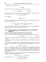
Figure 23.6 shows the figures that result from executing the previous code sam
-
ple. The second polyline is shown in dashed lines to visually distinguish it from
the first one. However, in an actual drawing there is no way of changing pens in
-
side a call to PolyPolyline().
622
Chapter 23
Figure 23.6
Coordinates of Two Polylines in the Sample Code
23.4.6 Drawing with Arc()
The Arc() function draws an elliptical arc. It is also used to draw circles, since the cir-
cle is a special case of the ellipse. The function's general form is as follows:
BOOL Arc(
HDC hdc, // 1
int nLeftRect, // 2
int nTopRect, // 3
int nRightRect, // 4
int nBottomRect, // 5
int nXStartArc, // 6
int nYStartArc, // 7
int nXEndArc, // 8
int nYEndArc // 9
);
The second and third parameters are the x- and y-coordinates of the upper-left
corner of a rectangle that contains the ellipse, while the fourth and fifth parameters
are the coordinates of its lower-right corner. By using a bounding rectangle to define
the ellipse, the Windows API avoids dealing with elliptical semi-axes. However,
whenever necessary, the bounding rectangle can be calculated from the semi-axes.
The sixth and seventh parameters define the coordinates of a point that sets the
start point of the elliptical arc. The last two parameters set the end points of the el
-
liptical arc. The elliptical arc is always drawn in the counterclockwise direction.
The SetArcDirection() function has no effect in this case.
The coordinates of the start and end points of the elliptical arc need not coincide
with the arc itself. Windows draws an imaginary line from the center of the ellipse to
the start and end points. The point at which this line (or its prolongation) intersects
the elliptical arc is used as the start or end point. If the start and end points are the
same, then a complete ellipse is drawn. The following code fragment draws an ellip
-
tical arc:
Drawing Lines and Curves
623
x = 160
y = 160
x = 300
y = 160
x = 300
y = 300
x = 160
y = 300
x=30
0
y=23
0
x = 230
y = 300
x = 160
y = 230
x = 230
y = 160
Arc (hdc,
150, 150, // upper-left of rectangle
350, 250, // lower-right
250, 260, // start point
200, 140; // end point
Figure 23.7 shows the location of each of the points in the preceding call to the
Arc() function and the resulting ellipse.
Figure 23.7
Coordinates of an Elliptical Arc in Sample Code
23.4.7 Drawing with ArcTo()
ArcTo() is a version of the Arc() function that updates the current pen position to the
end point of the elliptical arc. This function requires Windows NT Version 3.1 or later.
It is not available in Windows 95 or later. The function parameters are identical to
those of the Arc() function.
23.4.8 Drawing with AngleArc()
The AngleArc() function draws a straight line segment and an arc of a circle. The
straight line segment is from the current pen position to the arc's starting point. The
arc is defined by the circle's radius and two angles: the starting position, in degrees,
relative to the x-axis, and the angle sweep, also in degrees, relative to the starting po
-
sition. The arc is drawn in a counterclockwise direction. The function's general form
is as follows:
BOOL AngleArc(
HDC hdc, // 1
int X, // 2
int Y, // 3
DWORD dwRadius, // 4
FLOAT eStartAngle, // 5
FLOAT eSweepAngle // 6
);
624
Chapter 23
x = 150
y = 150
x = 350
y = 250
bounding
rectan
g
le
x=
200
y = 140
(start point)
(end point)
drawing
direction
x = 250
y = 260
The second and third parameters are the coordinates of the center of the circle that
defines the arc, in logical units. The fourth parameter is the radius of the circle, also
in logical units. The fifth parameter is the start angle in degrees, relative to the x-axis.
The last parameter is the sweep angle, also in degrees, relative to the angle's starting
position. Figure 23.8 shows the various elements in the AngleArc() function.
Figure 23.8
AngleArc() Function Elements
The AngleArc() function is not available in Windows 95 or later; however, it can
be emulated in code. Microsoft Developers Network contains the following listing
which allows implementing the AngleArc() function in software:
BOOL AngleArc2(HDC hdc, int X, int Y, DWORD dwRadius,
float fStartDegrees, float fSweepDegrees) {
int iXStart, iYStart; // End point of starting radial line
int iXEnd, iYEnd; // End point of ending radial line
float fStartRadians; // Start angle in radians
float fEndRadians; // End angle in radians
BOOL bResult; // Function result
float fTwoPi = 2.0f * 3.141592f;
/* Get the starting and ending angle in radians */
if (fSweepDegrees > 0.0f) {
fStartRadians = ((fStartDegrees / 360.0f) * fTwoPi);
fEndRadians = (((fStartDegrees + fSweepDegrees) / 360.0f) *
fTwoPi);
} else {
fStartRadians = (((fStartDegrees + fSweepDegrees) / 360.0f) *
fTwoPi);
fEndRadians = ((fStartDegrees / 360.0f) * fTwoPi);
}
/* Calculate a point on the starting radial line via */
/* polar -> cartesian conversion */
iXStart=X+(int)((float)dwRadius * (float)cos(fStartRadians));
iYStart=Y-(int)((float)dwRadius * (float)sin(fStartRadians));
/* Calculate a point on the ending radial line via */
/* polar -> cartesian conversion */
iXEnd=X+(int)((float)dwRadius * (float)cos(fEndRadians));
iYEnd=Y-(int)((float)dwRadius * (float)sin(fEndRadians));
Drawing Lines and Curves
625
circle center
and pen position
segment
and arc
radius
start angle
sweep angle
/* Draw a line to the starting point */
LineTo(hdc, iXStart, iYStart);
/* Draw the arc */
bResult = Arc(hdc, X - dwRadius, Y - dwRadius,
X + dwRadius, Y + dwRadius,
iXStart, iYStart,
iXEnd, iYEnd);
// Move to the ending point - Arc() wont do this and ArcTo()
// wont work on Win32s or Win16 */
MoveToEx(hdc, iXEnd, iYEnd, NULL);
return bResult;
}
Notice that the one documented difference between the preceding listing of
AngleArc2(), and the GDI AngleArc() function, is that if the value entered in the
sixth parameter exceeds 360 degrees, the software version will not sweep the an
-
gle multiple times. In most cases this is not a problem.
The program named PXL_DEMO, in the Pixel and Line Demo project folder on
the book's on-line software package, uses the AngleArc2() function to display a
curve similar to the one in Figure 23.8.
23.4.9 Drawing with PolyBezier()
In mechanical drafting, a spline is a flexible edge that is used to connect several
points on an irregular curve. Two French engineers, Pierre Bezier and Paul de
Casteljau, almost simultaneously discovered a mathematical expression for a
spline curve that can be easily adapted to computer representations. This curve is
known as the Bezier spline or curve, since it was Bezier who first published his find
-
ings. The Bezier curve is defined by its end points, called the nodes, and by one or
more control points. The control points serve as magnets or attractors that"pull" the
curve in their direction, but never enough for the curve to intersect the control
point. Figure 23.9 shows the elements of a simple Bezier curve.
Figure 23.9
The Bezier Spline
The Bezier curve in Figure 23.9 can be generated by a geometrical method that
consists of creating a series of progressively smaller line segments. The process,
626
Chapter 23
start node
B
e
zi
e
r
cu
rv
e
end node
contro
l
po
i
nt
(attractor)
sometimes called the divide and conquer method, starts by joining the half-way
points between the nodes and the attractor, thus creating a new set of nodes and a
new attractor. The process continues until a sufficiently accurate approximation of
the spline is reached. Figure 23.10 shows the progressive steps in creating a Bezier
spline by this method.
Figure 23.10
Divide-and-Conquer Method of Creating a Bezier Curve
In Step 1of Figure 23.10, we see the start node S1, the end node E1, and the attrac-
tor A1. We first find a point midway between S1 and A1 and label it P1. Another
point midway between A1 and E1 is labeled P2. Points P1 and P2 are joined by a line
segment, whose midpoint is labeled P3. In Step 2 we can see two new figures. The
first one has nodes at S2 and E2, and the attractor at A2. The second figure has
nodes at S3 and E3, and the attractor at A3. In Step 3 we have joined the midpoints
between the nodes and the attractors with a line segment, thus continuing the pro
-
cess. The two new figures have their new respective nodes and attractors, so the
process can be again repeated. In Step 3 we can see how the resulting line segments
begin to approximate the Bezier curve in Figure 23.9.
The divide and conquer process makes evident the fundamental assumption of
the Bezier spline: the curve is in the same direction and tangent to straight lines
from the nodes to the attractors. A second assumption is that the curve never inter
-
sects the attractors. The Bezier formulas are based on these assumptions.
The Bezier curve generated by the divide and conquer method is known as a qua
-
dratic Bezier. In computer graphics the most useful Bezier is the cubic form. In the
cubic form the Bezier curve is defined by two nodes and two attractors. The devel
-
opment of the cubic Bezier is almost identical to that of the quadratic. Figure 23.11,
on the following page, shows the elements of a cubic Bezier curve.
Drawing Lines and Curves
627
STEP 1:
STEP 2:
STEP 3:
S
1
S
2
S
4
S
5
A
5
E
5
A
4
E
4
E
2
A
2
A
3
S
3
E
3
P
3
P
2
P
1
A
1
E
1
Figure 23.11
Elements of the Cubic Bezier
The PolyBezier() function, introduced in Windows 95, draws one or more cubic
Bezier curves, each one defined by its nodes and two attractors. The function can
be called to draw multiple Bezier curves. In this case the first curve requires four
parameters, and all the other curves require three parameters. This is because the
end node of the preceding Bezier curve serves as the start node for the next one.
PolyBezier() does not change the current pen position. The Bezier curve is drawn
using the pen selected in the device context. The function's general form is as fol-
lows:
BOOL PolyBezier(
HDC hdc, // 1
CONST POINT *lppt, // 2
DWORD cPoints // 3
);
The first parameter is the handle to the device context. The second parameter
is the address of an array of points that contains the x- and y-coordinate pairs for
the nodes and control points. The third parameter is the count of the number of
points in the array. This value must be one more than three times the number of
curves to be drawn. For example, if the PolyBezier() function is called to draw
four curves, there must be 13 coordinate pairs in the array (1 + (3 * 4)). The func
-
tion returns TRUE if it succeeds and FALSE otherwise.
The Bezier data is stored in the array of points in a specific order. In the first
Bezier curve, the first and fourth entries are the nodes and the second and third
are attractors. Note that in the array the first and fourth entries are at offset 0 and
3 respectively, and the second and third entries are at offset 1 and 2. If there are
other Bezier curves in the array, the first node is not explicit in the data, since it
coincides with the end node of the preceding curve. Therefore, after the first
curve, the following two entries are attractors, and the third entry is the end node.
Table 23.6 shows the sequence of nodes and control points for an array with multi
-
ple Bezier curves.
628
Chapter 23
start node
f
irst
control
point
second
control
point
end node
Bezier spline