Software Solution for Engineers and Scientist Episode 9 potx
Bạn đang xem bản rút gọn của tài liệu. Xem và tải ngay bản đầy đủ của tài liệu tại đây (406.71 KB, 90 trang )
HBITMAP SelectBitmap (HDC, HBITMAP);
|
||
12
The first parameter must be the handle of a memory device context. The sec
-
ond parameter is the handle to the bitmap being installed. If the call succeeds, the
macro returns the handle to the device context object being replaced. If the call
fails, it returns NULL. Using the SelectBitmap() macro instead of the
SelectObject() function produces code that is correct and the coding is made eas
-
ier. Recall that programs that use the object selection macros must include the
windowsx.h file.
The handle to the bitmap used in the SelectBitmap() macro is usually obtained
with the LoadBitmap() function previously discussed.
25.3.3 Obtaining Bitmap Dimensions
Bitmap functions often require information about the dimensions and other charac
-
teristics of the bitmap. For example, the function most often used to display a
bitmap is BitBlt(); it requires the width and height of the bitmap. If the bitmap is
loaded as a resource from a file, the application must obtain the bitmap dimensions
before blitting it to the screen. The GetObject() function is used to obtain informa-
tion about a bitmap. The function's general form is as follows:
int GetObject(
HGDIOBJ hgdiobj, // l
int cbBuffer, // 2
LPVOID lpvObject // 3
);
The first parameter is the handle to a graphics object; in this case, the handle to
a bitmap. The second parameter is the size of the buffer that holds the informa
-
tion returned by the call. In the case of a bitmap, this parameter can be coded as
sizeof (BITMAP). The third parameter is a pointer to the buffer that holds the in
-
formation returned by the call. In the case of a bitmap, the buffer is a structure
variable of type BITMAP. The BITMAP structure is defined as follows:
typedef struct tagBITMAP {
LONG bmType; // Must be zero
LONG bmWidth; // bitmap width (in pixels)
LONG bmHeight; // bitmap height (in pixels)
LONG bmWidthBytes; // bytes per scan line
WORD bmPlanes; // number of color planes
WORD bmBitsPixel; // bits per pixel color
LPVOID bmBits; // points to bitmap values array
} BITMAP;
The structure member bmType specifies the bitmap type. It must be zero. The
member bmWidth specifies the width, in pixels, of the bitmap. Its value must be
greater than zero. The member bmHeight specifies the height, in pixels, of the
bitmap. The height must be greater than zero. The bmWidthBytes member speci
-
fies the number of bytes in each scan line. Since Windows assumes that the
bitmap is word-aligned, its value must be divisible by 2. The member bmPlanes
694
Chapter 25
specifies the number of color planes. The member bmBitsPixel specifies the number
of bits required to indicate the color of a pixel. The member bmBits points to the lo
-
cation of the bit values for the bitmap. It is a long pointer to an array of charac
-
ter-size values.
When the target of the GetObject() call is a bitmap, the information returned is
the structure members related to the bitmap width, height, and color format. The
GetObject() function cannot be used to read the value of the pointer to the bitmap
data in the bmBits structure member. GetDIBits() retrieves the bit data of a bitmap.
The mapping mode can also be a factor in regard to bitmap data. The GetObject()
function returns the bitmap width and height in the BITMAP structure. The values
returned are in pixels, which are device units. This works well if the mapping mode
of the memory device context is MM_TEXT, but is not acceptable in any of the map
-
ping modes that use logical units. The DPtoLP() function allows the conversion of
device coordinates (pixels) into logical coordinates for a particular device context.
The function's general form is as follows:
BOOL DPtoLP(
HDC hdc, // 1
LPPOINT lpPoints, // 2
int nCount // 3
);
The first parameter identifies the device context. In the case of a bitmap, it is a
memory device context. The second parameter points to an array of POINT struc-
tures that holds the transformed values for the x- and y-coordinates. The third pa-
rameter holds the number of points in the array specified in the second parameter.
The function returns TRUE if it succeeds and FALSE if it fails.
A bitmap size is defined by two values: the x-coordinate is the width and the
y-coordinate the height. When a call to DPtoLP() is made to obtain the bitmap size,
the third parameter is set to 1. This indicates that the coordinates to be transformed
refer to a single point. By the same token, the second parameter is a pointer to a sin
-
gle POINT structure that holds the bitmap width in the x member and the bitmap
height in the y member.
25.3.4 Blitting the Bitmap
Once a bitmap has been selected onto a memory device context, and the code has ob
-
tained the necessary information about its width and height, it is possible to display it
at any screen position by blitting the memory stored bitmap onto the screen. The
BitBlt() function is the simplest and most direct method of performing the bitmap dis
-
play operation. The function's general form is as follows:
BOOL BitBlt(
HDC hdcDest, // 1
int nXDest, // 2
int nYDest, // 3
int nWidth, // 4
int nHeight, // 5
HDC hdcSrc, // 6
Displaying Bit-Mapped Images
695
int nXSrc, // 7
int nYSrc, // 8
DWORD dwRop // 9
);
The first parameter identifies the destination device context. If the call to
BitBlt() is made to display a bitmap, this will be the display context. The second
and third parameters are the x- and y-coordinates of the upper-left corner of the
destination rectangle. Which is also the screen location where the upper-left cor
-
ner of the bitmap is displayed. The fourth and fifth parameters are the width and
height of the bitmap, in logical units. The sixth parameter is the source device
context. In the case of a bitmap display operation, this parameter holds the mem
-
ory device context where the bitmap is stored. The seventh and eighth parameters
are the x- and y-coordinates of the source bitmap. Since the blitted rectangles
must be of the same dimensions, as defined by the fourth and fifth parameters, the
seventh and eighth parameters are usually set to zero.
The ninth parameter defines the raster operation code. These codes are called
ternary raster operations. They differ from the binary raster operation codes
(ROP2) discussed in Chapter 22 in that the ternary codes take into account the
source, the destination, and a pattern determined by the brush currently selected
in the device context. There are 256 possible raster operations, fifteen of which
have symbolic names defined in the windows.h header file. The raster operation
code determines how the color data of the source and destination rectangles, to-
gether with the current brush, are to be combined. Table 25.2 lists the fifteen ras-
ter operations with symbolic names.
Table 25.2
Symbolic Names for Raster Operations
NAME DESCRIPTION
BLACKNESS Fills the destination rectangle using the color
associated with index 0 in the physical palette. The
default value is black.
DSTINVERT Inverts the destination rectangle.
MERGECOPY Merges the colors of the source rectangle with the
specified pattern using an AND operation.
MERGEPAINT Merges the colors of the inverted source rectangle with
the colors of the destination rectangle using an
OR operation.
NOTSRCCOPY Inverts the bits in the source rectangle and copies it to
The destination.
NOTSRCERASE Combines the colors of the source and destination
rectangles using an OR operation, and then inverts the
result.
PATCOPY Copies the specified pattern to the destination
bitmap.
PATINVERT Combines the colors of the specified pattern with the
colors of the destination rectangle using an XOR
operation.
(continues)
696
Chapter 25
Table 25.2
Symbolic Names for Raster Operations (continued)
NAME DESCRIPTION
PATPAINT Combines the colors of the pattern with the colors of
the inverted source rectangle using an OR operation.
The result of this operation is combined with the colors
of the destination rectangle using an OR operation.
SRCAND Combines the colors of the source and destination
rectangles using an AND operation SRCCOPY.
Copies the source rectangle directly to the destination
rectangle. This is, by far, the most-used mode in bitblt
operations.
SRCERASE Combines the inverted colors of the destination rectangle
with the colors of the source rectangle using an AND
operation.
SRCINVERT Combines the colors of the source and destination
rectangles using an XOR operation.
SRCPAINT Combines the colors of the source and destination
rectangles using an OR operation.
WHITENESS Fills the destination rectangle using the color associated
with index 1 in the physical palette. The default value is
White.
25.3.5 A Bitmap Display Function
Displaying a bitmap is a multistage process that includes the following operations:
1. Creating a memory device context.
2. Selecting the bitmap into the memory device context.
3. Obtaining the bitmap dimensions and converting device units to logical units.
4. Blitting the bitmap onto the screen according to a ternary raster operation code.
Many graphics applications can make use of a function that performs all of the
previous operations. The function named ShowBitmap() is used in the Bitmap Demo
project on the book's software on-line. The function's prototype is as follows:
void ShowBitmap (HDC, HBITMAP, int, int, DWORD);
| | |
|||||
12345
The first parameter is the handle to the device context. The ShowBitmap() func
-
tion creates its own memory device context. The second parameter is the handle to
the bitmap that is to be displayed. The third and fourth parameters are the screen
coordinates for displaying the upper-left corner of the bitmap. The fifth parameter is
the ternary ROP code used in blitting the bitmap. If this parameter is NULL then the
bitmap is displayed using the SRCCOPY raster operation. The following is a listing
of the ShowBitmap() function:
Displaying Bit-Mapped Images
697
void ShowBitmap (HDC hdc, HBITMAP hBitmap, int xStart, int yStart,\
DWORD rop3) {
BITMAP bm; // BITMAP structure
HDC memoryDc; // Handle to memory DC
POINT ptSize; // POINT for DC
POINT ptOrigin; // POINT for memory DC
int mapMode; // Mapping mode
// Test for NULL ROP3 code
if (rop3 == NULL)
rop3 = SRCCOPY;
memoryDc = CreateCompatibleDC (hdc); // Memory device
// handle
mapMode = GetMapMode (hdc); // Obtain mapping
// mode
SetMapMode (memoryDc, mapMode); // Set memory DC
// mapping mode
// Select bitmap into memory DC
// Note: assert statement facilitates detecting invalid
// bitmaps during program development
assert (SelectBitmap (memoryDc, hBitmap));
// Obtain bitmap dimensions
GetObject (hBitmap, sizeof(BITMAP), (LPVOID) &bm);
// Convert device units to logical units
ptSize.x = bm.bmWidth;
ptSize.y = bm.bmHeight;
DPtoLP (hdc, &ptSize, 1);
ptOrigin.x = 0;
ptOrigin.y = 0;
DPtoLP (memoryDc, &ptOrigin, 1);
// Bitblt bitmap onto display memory
BitBlt( hdc, xStart, yStart, ptSize.x, ptSize.y, memoryDc,
ptOrigin.x, ptOrigin.y, rop3);
// Delete memory DC with bitmap
DeleteDC (memoryDc);
}
25.4 Bitmap Manipulations
In addition to displaying a bitmap stored in a disk file, graphics applications often
need to perform otherbitmap-related operations. The following are among the most
common operations:
•
Creating and displaying a hard-coded bitmap
•
Creating a bitmap in heap memory
•
Creating a blank bitmap and filling it by means of GDI functions
•
Creating a system-memory bitmap which applications can access directly
698
Chapter 25
•
Using a bitmap to create a pattern brush
25.4.1 Hard-Coding a Monochrome Bitmap
With the facilities available in Developer Studio for creating bitmaps, the programmer
is seldom forced to hard-code a bitmap. Our rationale for discussing this option is that
hard-coding bitmaps is a basic skill for a programmer, and that it helps to understand
bitmaps in general.
A monochrome bitmap has one color plane and is encoded in a one-bit-per-pixel
format. In Windows, a monochrome bitmap is displayed by showing the 0-bits in the
foreground color and the 1-bits in the background color. If the screen has a white
foreground and a black background, 0-bits in the bitmap are displayed as white pix
-
els, and vice versa. If the bitmap is to be blitted on the screen using the BitBlt() func
-
tion, the action of the bits can be reversed by changing the raster operation code.
This gives the programmer the flexibility of using either zero or one bits for back
-
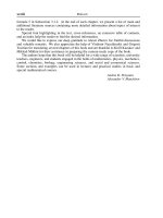
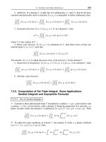
ground or foreground attributes. Figure 25.4 shows a hard-coded monochrome
bitmap.
Figure 25.4
Hard-Coded, Monochrome Bitmap
Displaying Bit-Mapped Images
699
0
0
1
2
3
4
5
6
7
8
9
431
bitmap:
2
01234
0- 0xC6 0x7C 0xC1 0x81 0xF0
1- 0xC6 0x7C 0xC1 0x83 0xF8
2- 0xC6 0x60 0xC1 0x83 0x18
3- 0xC6 0x60 0xC1 0x83 0x18
4- 0xFE 0x78 0xC1 0x83 0x18
5- 0xFE 0x78 0xC1 0x83 0x18
6- 0xC6 0x60 0xC1 0x83 0x18
7- 0xC6 0x60 0xC1 0x83 0x18
8- 0xC6 0x7C 0xF9 0xF3 0xF8
9- 0xC6 0x7C 0xF9 0xF1 0xF0
11000110=0xC6
effective size = 37 pixels
In Figure 25.4 the dark pixels in the image are represented by 0-bits in the
bitmap. The resulting data structure has five bytes per scan line and a total of 10
scan lines. The illustration shows how eight pixels in the bottom row of the image
are represented by eight bits (one byte) of the bitmap. The dark pixels are en
-
coded as 0-bits and the light pixels as 1-bits. In order to display this bitmap so that
the letters are black on a white screen background, the black and white pixels
have to be reversed by changing the raster operation mode from the default value,
SCRCOPY, to NOTSCRCOPY, as previously explained.
Once the bit image of a monochrome bitmap has been calculated, we can pro
-
ceed to store this bit-to-pixel information in an array of type BYTE. Windows re
-
quires that bitmaps be word-aligned; therefore, each scan line in the array must
have a number of bytes divisible by 2. In regards to the bitmap in Figure 25.4, you
would have to add a padding byte to each scan line in order to satisfy this require
-
ment. The resulting array could be coded as follows:
// 012345
static BYTE hexBits[] = {0xc6, 0x7c, 0xc1, 0x81, 0xf0, 0x0,
0xc6, 0x7c, 0xc1, 0x83, 0xf8, 0x0,
0xc6, 0x60, 0xc1, 0x83, 0x18, 0x0,
0xc6, 0x60, 0xc1, 0x83, 0x18, 0x0,
0xfe, 0x78, 0xc1, 0x83, 0x18, 0x0,
0xfe, 0x78, 0xc1, 0x83, 0x18, 0x0,
0xc6, 0x60, 0xc1, 0x83, 0x18, 0x0,
0xc6, 0x60, 0xc1, 0x83, 0x18, 0x0,
0xc6, 0x7c, 0xf9, 0xf3, 0xf8, 0x0,
0xc6, 0x7c, 0xf9, 0xf1, 0xf0, 0x0};
// |
// padding byte |
The CreateBitmap() function can be used to create a bitmap given the
bit-to-pixel data array. The function's general form is as follows:
HBITMAP CreateBitmap(
int nWidth, // 1
int nHeight, // 2
UINT cPlanes, // 3
UINT cBitsPerPel, // 4
CONST VOID *lpvBits // 5
);
The first parameter is the actual width of the bitmap, in pixels. In relation to
the bitmap in Figure 25.4, this value is 37 pixels, as shown in the illustration. The
second parameter is the number of scan lines in the bitmap. The third parameter
is the number of color planes. In the case of a monochrome bitmap this value is 1.
The fourth parameter is the number of bits per pixel. In a monochrome bitmap
this value is also 1. The fifth parameter is a pointer to the location where the
bitmap data is stored. If the function succeeds, the returned value is the handle to
a bitmap. If the function fails, the return value is NULL. The following code frag
-
ment initializes a monochrome bitmap using the bitmap data in the hexBits[] ar
-
ray previously listed:
static HBITMAP bmImage1;
.
700
Chapter 25
.
.
// Initialize monochrome bitmap
bmImage1 = CreateBitmap (37, 10, 1, 1, hexBits);
Alternatively, a bitmap can be defined using a structure of type BITMAP, listed
previously in this chapter and in Appendix F. Before the bitmap is created, the struc
-
ture members must be initialized, as in the following code fragment:
static BITMAP monoBM;
.
.
.
// Initialize data structure for a monochrome bitmap
monoBM.bmType = 0; // must be zero
monoBM.bmWidth = 37; // actual pixels used
monoBM.bmHeight = 10; // scan lines
monoBM.bmWidthBytes = 6; // width (must be word aligned)
monoBM.bmPlanes = 1; // 1 for monochrome bitmaps
monoBM.bmBitsPixel = 1; // 1 for monochrome bitmaps
monoBM.bmBits = (LPVOID) &hexBits; // address of bit field
When the bitmap data is stored in a structure of type BITMAP, the bitmap can be
created by means of the CreateBitmapIndirect() function. The function's general
form is as follows:
HBITMAP CreateBitmapIndirect(
CONST BITMAP *lpbm // 1
);
The function's only parameter is a pointer to a structure of type BITMAP. If the
function succeeds, the returned value is the handle to a bitmap. If the function fails,
the return value is NULL. The following code fragment uses CreateBitmapIndirect()
to initialize a monochrome bitmap using the bitmap data in the hexBits[] array pre
-
viously listed:
static HBITMAP bmImage1;
.
.
.
// Initialize monochrome bitmap
bmImage1 = CreateBitmapIndirect (&monoBM);
Whether the bitmap was created using CreateBitmap() or
CreateBitmapIndirect(), it can now be displayed by means of the ShowBitmap()
function developed and listed previously in this chapter.
25.4.2 Bitmaps in Heap Memory
A bitmap can take up a considerable amount of memory or storage resources. For ex
-
ample, a 1200-by-1200 pixel bitmap encoded in 32-bit color takes up approximately 5.7
Mb. Applications that store large bitmaps in their own memory space can run into
memory management problems. One possible solution is to store large bitmaps in dy
-
namically allocated memory, which can be freed as soon as the bitmap is no longer
needed. Note that freeing memory where the bitmap is stored does not affect the
screen image.
Displaying Bit-Mapped Images
701
Several programming techniques can be used to allocate and release heap
memory for a bitmap. The one most suitable depends on the particular needs of
each particular programming problem. In one case you may allocate heap memory
for a bitmap during WM_CREATE message processing, and then use this allocated
space to create or copy different bitmaps during program execution. The allo
-
cated memory can then be freed during WM_DESTROY processing. Another op
-
tion is to allocate memory at the time it is required, create or copy the bitmap to
this allocated space, and deallocate the memory when the bitmap is no longer
needed.
Many fables and fantastic theories have originated in the complications and
misunderstandings of Windows memory management. Although most of these
problems were corrected in Windows 3.1, an entire programming subculture still
thrives on discussions related to these topics. A programmer encountering mem
-
ory management in Windows finds that there are three separate sets of memory al
-
location and deallocation operators that serve apparently identical purposes: the
C++ operators new and delete, the traditional C operators malloc and free, and
the Windows kernel functions LocalAlloc(), GlobalAlloc(), LocalFree(), and
GlobalFree().
In Win32 programming, the first simplification is a result of the fact that there
is no difference between the global and the local heaps. Therefore, GlobalAlloc()
and LocalAlloc(), as well as GlobalFree() and LocalFree(), actually perform virtu-
ally identical functions. Because of their greater flexibility we will use
GlobalAlloc() and GlobalFree() instead of new and delete or malloc and free oper-
ators from the C++ and C libraries. Another reason for this preference is that
most Windows compilers implement malloc and new in terms of GlobalAlloc();
therefore, the traditional operators offer no advantage.
Traditionally, three types of memory are documented as being available to ap
-
plications: fixed memory, moveable memory, and discardable memory. The justifi
-
cation for preferring moveable memory disappeared with Windows 95, in which a
memory block can be moved in virtual memory while retaining the same address.
For the same reason, the use of fixed memory no longer needs to be avoided.
Discardable memory is only indicated when the data can be easily recreated,
which is not usually the case with image data structures. In conclusion, fixed
memory is usually quite suitable for dynamically storing bitmaps and other image
data.
Note that the terms moveable and movable are both accepted, although mov
-
able is preferred. However, the Windows API contains the constants
GMEM_MOVEABLE and LMEM_MOVEABLE. For this reason we have used the
former.
In this section we discuss the bare essentials of memory allocation and
deallocation in Windows. The topic of Windows memory management can easily
fill a good-size volume. Graphics applications are often memory-intensive and
may require sophisticated memory management techniques. A graphics program
-
702
Chapter 25
mer should have a thorough knowledge of Win32 memory architecture, virtual mem
-
ory, and heap management. The book Advanced Windows, by Richter (see
Bibliography) has chapters devoted to each of these topics.
The GlobalAlloc() function is used to allocate memory from the default heap. The
default heap is initially 1Mb, but under Windows, this heap grows as it becomes nec
-
essary. The function's general form is as follows:
HGLOBAL GlobalAlloc(
UINT uFlags, // 1
DWORD dwBytes // 2
);
The first parameter is a flag that determines how memory is allocated to the
caller. Table 25.3 lists the most commonly used allocation flags. The second parame
-
ter is the number of bytes of memory to be allocated. If it succeeds, the function re
-
turns the handle to the allocated memory object. If the allocation flag is
GMEM_FIXED, the handle can be directly cast into a pointer and the memory used.
If the allocated memory is not fixed, then it must be locked using GlobalLock() be
-
fore it can be used by code. The function returns NULL if the allocation request fails.
Table 25.3
Win-32 Commonly Used Memory Allocation Flags
FLAG MEANING
GMEM_FIXED Allocates fixed memory. This flag cannot be
combined with the GMEM_MOVEABLE or
GMEM_DISCARDABLE flag. The return value is a
pointer to the memory block.
GMEM_MOVEABLE Allocates moveable memory. This flag cannot be
combined with the GMEM_FIXED flag. The return
value is the handle of the memory object, which is
a 32-bit quantity private to the calling process.
GMEM_DISCARDABLE Allocates discardable memory. This flag cannot be
combined with the flag. Win32-based operating
systems ignore this flag.
GMEM_ZEROINIT Initializes memory to 0.
GPTR Combines the GMEM_FIXED and
GMEM_ZEROINIT flags.
GHND Combines the GMEM_MOVEABLE and
GMEM_ZEROINIT flags.
The process of creating a bitmap in heap memory and displaying it on the video
screen can be accomplished by the following steps:
1. Dynamically allocate the memory required for the bitmap and the corresponding data
structures.
2. Store the bitmap data and the bitmap dimensions and color information, thus creating
a DIB.
3. Convert the device independent bitmap (DIB) into a device dependent bitmap using
CreateDIBitmap().
4. Display the bitmap using SetDIBitsToDevice().
Displaying Bit-Mapped Images
703
Suppose you wanted to create a 200-pixel wide bitmap, with 255 scan lines, in
32-bit color. Since each pixel requires four bytes, each scan line consists of 800
bytes, and the entire bitmap occupies 204,000 bytes. A BITMAPINFO structure
variable is used to hold the bitmap information. Notice that because this is a
true-color bitmap, the RGBQUAD structure is not necessary. In this case the mem
-
ory allocation operations can be coded as follows:
static PBITMAPINFO pDibInfo; // pointer to BITMAPINFO structure
static BYTE *pDib; // pointer to bitmap data
.
.
.
pDibInfo = (PBITMAPINFO) LocalAlloc(LMEM_FIXED, \
sizeof(BITMAPINFOHEADER));
pDib = (BYTE*) LocalAlloc(LMEM_FIXED, 204000);
At this point the code has allocated memory for both the bitmap and the
BITMAPINFOHEADER structure variable that is to hold the bitmap format infor
-
mation. The pointers to each of these memory areas can be used to fill them in.
First the bitmap information:
pDibInfo->bmiHeader.biSize = (LONG) sizeof(BITMAPINFOHEADER);
pDibInfo->bmiHeader.biWidth = (LONG) 200; // pixel width
pDibInfo->bmiHeader.biHeight = (LONG) 255; // pixel height
pDibInfo->bmiHeader.biPlanes = 1; // number of planes
pDibInfo->bmiHeader.biBitCount = 32; // bits per pixel
Assume that the bitmap is to represent a blue rectangle with 255 decreasing in-
tensities of blue, along the scan lines. The code to fill this bitmap can be coded as
follows:
int i, j, k; // counters
BYTE shade; // shade of blue
.
.
.
// Fill the bitmap using 32-bit color data
// < 200 pixels (4 bytes each) >
// |
// | 255 scan lines
shade = 0;
for (k = 0; k < 255; k++){ // Counts 255 scan lines
for (i = 0; i < 200; i++){ // Counts 200 pixels
for(j = 0;j<4;j++) { // Counts 4 bytes
pDib[((k*800)+(i*4)+0] = shade; // blue
pDib[((k*800)+(i*4)+1] = 0; // green
pDib[((k*800)+(i*4)+2] = 0; // red
pDib[((k*800)+(i*4)+3] = 0; // must be zero
};
};
shade++;
};
Now that the bitmap data structures have been initialized and the bitmap data
entered into the allocated heap memory, it is time to create the device-dependent
bitmap that can be displayed on the display context. The function used for this
704
Chapter 25
purpose is named CreateDIBitmap(); this name is somewhat confusing since it actu
-
ally creates a dependent device from a device-independent bitmap. The function's
general form is as follows:
HBITMAP CreateDIBitmap(
HDC hdc, // 1
CONST BITMAPINFOHEADER *lpbmih, // 2
DWORD fdwInit, // 3
CONST VOID *lpbInit, // 4
CONST BITMAPINFO *lpbmi, // 5
UINT fuUsage // 6
);
The first parameter is the handle to the device context for which the device de
-
pendent bitmap is to be configured. The second parameter is a pointer to a
BITMAPINFOHEADER structure variable that contains the bitmap data. The third
parameter is a flag that determines how the operating system initializes the bitmap
bits. If this parameter is zero the bitmap data is not initialized and parameters 4 and
5 are not used. If it is set to CBM_INIT, then parameters 4 and 5 are used as pointers
to the data used in initializing the bitmap bits. The fourth parameter is a pointer to
the array of type BYTE that contains the bitmap data. The fifth parameter is a
pointer to a BITMAPINFO structure that contains the bitmap size and color data.
The sixth parameter is a flag that determines whether the bmiColors member of the
BITMAPINFO structure contains explicit color values in RGB format or palette indi-
ces. In the first case the constant DIB_RGB_COLORS is used for this parameter, and
in the second case the constant is DIB_PAL_COLORS. The function returns the han-
dle to the bitmap if it succeeds, or NULL if it fails.
In the example that we have been following, the device dependent bitmap is cre-
ated as follows:
static HBITMAP hBitmap; // handle to a bitmap
.
.
.
hBitmap = CreateDIBitmap ( hdc,
(LPBITMAPINFOHEADER) &pDibInfo->bmiHeader,
CBM_INIT,
(LPSTR) pDib,
(LPBITMAPINFO) pDibInfo,
DIB_RGB_COLORS );
Having obtained its handle, the bitmap can be displayed using the ShowBitmap()
function developed earlier in this chapter. Alternatively, you can use
SetDIBitsToDevice() to set the screen pixels. The function's general form is as fol
-
lows:
int SetDIBitsToDevice(
HDC hdc, // 1
int XDest, // 2
int YDest, // 3
DWORD dwWidth, // 4
DWORD dwHeight, // 5
int XSrc, // 6
Displaying Bit-Mapped Images
705
int YSrc, // 7
UINT uStartScan, // 8
UINT cScanLines, // 9
CONST VOID *lpvBits, // 10
CONST BITMAPINFO *lpbmi, // 11
UINT fuColorUse // 12
);
The first parameter is the handle to the display context to which the bitmap is
to be output. The second and third parameters are the x- and y-coordinates of the
destination rectangle, in logical units. This is the screen location where the
bitmap is displayed. The fourth and fifth parameters are the width and height of
the DIB. These values are often read from the corresponding members of the
BITMAPINFOHEADER structure variable that defines the bitmap. The sixth and
seventh parameters are the x- and y-coordinates of the lower-left corner of the
DIB. The eighth parameter is the starting scan line of the DIB. The ninth parame
-
ter is the number of scan lines. The tenth parameter is a pointer to the bitmap data
and the eleventh parameter is a pointer to the BITMAPINFO structure variable
that describes the bitmap. The twelfth parameter is a flag that determines
whether the bmiColors member of the BITMAPINFO structure contains explicit
color values in RGB format or palette indices. In the first case the constant
DIB_RGB_COLORS is used, and in the second case the constant
DIB_PAL_COLORS. If the function succeeds the return value is the number of
scan lines displayed. The function returns NULL if it fails.
In the current example, the bitmap can be displayed with the following call to
SetDIBitsToDevice():
SetDIBitsToDevice (hdc, 50, 50,
pDibInfo->bmiHeader.biWidth,
pDibInfo->bmiHeader.biHeight,
0, 0, 0,
pDibInfo->bmiHeader.biHeight,
pDib,
(BITMAPINFO FAR*) pDibInfo,
DIB_RGB_COLORS);
25.4.3 Operations on Blank Bitmaps
Sometimes an application needs to fill a blank bitmap using GDI functions. The
functions can include all the drawing and text display primitives discussed in previ
-
ous chapters. There are several programming approaches to creating a bitmap on
which GDI operations can be performed. The simplest approach is to select a
bitmap into a memory device context and then perform the draw operation on the
memory device context. Note that all the drawing functions discussed previously
require a handle to the device context. When the drawing takes place on a memory
DC, the results are not seen on the video display until the memory DC is blitted to the
screen. In this approach the following steps are required:
1. Select the bitmap into a memory device context using the SelectObject() function.
2. Clear or otherwise paint the bitmap using the PatBlt() function.
706
Chapter 25
3. Perform drawing operations on the memory device context that contains the bitmap.
4. Display the bitmap by blitting it on the screen, typically with BitBlt().
The CreateCompatibleBitmap() function has the following general form:
HBITMAP CreateCompatibleBitmap(
HDC hdc, // 1
int nWidth, // 2
int nHeight // 3
);
The first parameter is the handle to the device context with which the created
bitmap is to be compatible. If the bitmap is to be displayed this parameter is set to
the display context. The second and third parameters are the width and height of the
bitmap, in pixels. If the function succeeds it returns the handle to the bitmap. The
function returns NULL if it fails.
In the following code sample we create a blank, 300-by-300 pixel bitmap, draw a
rectangle and an ellipse on it, and then blit it to the screen. First we start by creating
the blank bitmap:
static HDC aMemDC; // memory device context
static HBITMAP bmBlank; // handle to a bitmap
static HGDIOBJ oldObject; // storage for current object
.
.
.
// Preliminary operations
aMemDC = CreateCompatibleDC (NULL); // Memory device handle
mapMode = GetMapMode (hdc); // Obtain mapping mode
SetMapMode (aMemDC, mapMode); // Set memory DC mapping mode
// Create the bitmap
bmBlank = CreateCompatibleBitmap (hdc, 300, 300);
oldObject = SelectObject (aMemDC, bmBlank);
Note that we use a generic handle (HGDIOBJ) to store the current handle in the
device context.
There is no guarantee that the bitmap thus created and selected into the device is
initialized. The PatBlt() function can be used to set all the bitmap bits to a particular
attribute or to a predefined pattern. The function's general form is as follows:
BOOL PatBlt(
HDC hdc, // 1
int nXLeft, // 2
int nYLeft, // 3
int nWidth, // 4
int nHeight, // 5
DWORD dwRop // 6
);
The first parameter is the handle to the device context, which can be a memory
device context. The second and third parameters are the x- and y-coordinates of the
upper-left corner of the rectangle to be filled. The fourth and fifth parameters are
the width and height of the bitmap, in logical units. The sixth parameter is one of the
Displaying Bit-Mapped Images
707
following constants: PATCOPY, PATINVERT, DSTINVERT, BLACKNESS, or
WHITENESS. The constants are defined in Table 25.2. The call returns TRUE if it
succeeds and FALSE if it fails.
Following the current example, the call clears the bitmap and sets all bits to the
white attribute:
PatBlt (aMemDC, 0, 0, 300, 300, WHITENESS);
At this point in the code we can start performing drawing operations on the
bitmap. The only requirement is that the drawing primitives reference the handle
to the memory device context where the blank bitmap was selected, as in the fol
-
lowing example:
Ellipse (aMemDC, 10, 10, 210, 110);
Polyline (aMemDC, rectangle, 5);
Once you have finished drawing on the blank bitmap, it can be displayed by
means of a bitblt, as in the following example:
BitBlt(hdc, 50, 50, 300, 300, aMemDC, 0, 0, SRCCOPY);
In this case, the call references both the display context (hdc) and the memory
device context containing the bitmap (aMemDC).
Clean-up operations consist of reselecting the original object to the memory
device context, then deleting the device context and the bitmap.
25.4.4 Creating a DIB Section
The methods described in the preceding section are satisfactory when the bitmap
area requires drawing operations that can be implemented by GDI functions, but
code has no direct access to the bitmap itself. This is due to the fact that
CreateCompatibleBitmap() does not return a pointer to the bitmap data area. The
CreateDIBSection() function, first introduced in Win32 and formalized in Windows
95, allows creating a device-independent bitmap that applications can access di
-
rectly.
Note that the original Windows documentation for Win32 contained incorrect
information about the CreateDIBSection() function and the associated
DIBSECTION structure. Some of the errors and omissions were later corrected so
that current documentation is more accurate, although not very clear.
Before CreateDIBSection(), an application would access bitmap data by calling
the GetDIBits() function, which copies the bitmap into a buffer supplied by the
caller. At the same time, the bitmap size and color data is copied into a
BITMAPINFO structure from which the application can read these values. After
the bitmap is changed, the SetDIBits() function is used to redisplay the bitmap.
Both functions, GetDIBits() and SetDIBits(), allow selecting the first scan line
and the number of scan lines. When operating on large bitmaps, this feature
makes it possible to save memory by reading and writing portions of it at a time.
708
Chapter 25
There are several shortcomings to modifying bitmaps at run time using
GetDIBits() and SetDIBits(). The most obvious one is that the system bitmap must
be copied into the application's memory space, then back into system memory. The
process is wasteful and inefficient. If the entire bitmap is read during the
GetDIBits() call, there are two copies of the same data, thus wasting memory. If it is
broken down into regions in order to reduce the waste, then processing speed suf
-
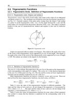
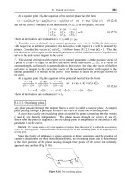
fers considerably. The solution offered by CreateDIBSection() is to create a bitmap
that can be accessed by both the system and the application. Figure 25.5 shows both
cases.
Although CreateDIBSection() provides a better alternative than GetDIBits() and
SetDIBits(), it is by no means the ultimate in high-performance graphics.
DirectDraw methods, not discussed in this book, provide ways of accessing video
memory directly and of taking advantage of raster graphics hardware accelerators.
In the following example, we create a DIB section, using the pointer returned by
the CreateDIBSection() call to fill the bitmap, and the bitmap handle to perform GDI
drawing functions on its memory space. The bitmap is 50 pixels wide and 255 scan
lines long. It is encoded in 32-bit true color format. The code starts by defining the
necessary data structures, initializing the variables, and allocating memory.
Figure 25.5
Memory Image of Conventional and DIB Section Bitmaps
Displaying Bit-Mapped Images
709
APPLICATION
MEMORY
SPACE
VIDEO
MEMORY
SYSTEM
MEMORY
SPACE
GetDIBits()
DIB
DDB
SetDIBits()
GDI operations
(via handle)
direct bit access
(via address)
DIB
SECTION
BitBlt()
HDC aMemDC; // Memory DC
static HBITMAP aBitmap;
static BYTE* lpBits;
BITMAPINFOHEADER bi;
BITMAPINFOHEADER* lpbi;
HANDLE hDIB;
int shade;
static int BMScanLines; // Bitmap y-dimension
static int BMWidth; // Bitmap x-dimension
.
.
.
// Initialize size variables
BMScanLines = 255;
BMWidth = 50;
// Initialize BITMAPINFOHEADER structure
bi.biSize = sizeof(BITMAPINFOHEADER);
bi.biWidth = BMWidth;
bi.biHeight = BMScanLines;
bi.biPlanes = 1;
bi.biBitCount = 32;
bi.biCompression = BI_RGB;
bi.biSizeImage = 0;
bi.biXPelsPerMeter = 0;
bi.biYPelsPerMeter = 0;
bi.biClrUsed = 0;
bi.biClrImportant = 0;
// Allocate memory for DIB
hDIB = GlobalAlloc (GMEM_FIXED, sizeof(BITMAPINFOHEADER));
// Initialize bitmap pointers
lpbi = (BITMAPINFOHEADER*) hDIB;
*lpbi = bi;
At this point everything is ready to call CreateDIBSection(). The function's gen
-
eral form is as follows:
HBITMAP CreateDIBSection(
HDC hdc, // 1
CONST BITMAPINFO *pbmi, // 2
UINT iUsage, // 3
VOID *ppvBits, // 4
HANDLE hSection, // 5
DWORD dwOffset // 6
);
The first parameter is the handle to a device context associated with the DIB
section. The second parameter is a pointer to a structure variable of type
BITMAPINFOHEADER, which holds the bitmap attributes. The first five members
of the BITMAPINFOHEADER structure are required; the other ones can often be
omitted, although it is usually a good idea to fill in the entire structure. The third
parameter is either the constant DIB_PAL_COLORS or DIB_RGB_COLORS. In the
first case the bmiColors array member of the RGBQUAD structure in
BITMAPINFO is a set of 16-bit palette color indices. In the second case the
bmiColors member is not used and the colors are encoded directly in the bitmap.
The fourth parameter is a pointer to a pointer to type VOID that contains the loca
-
710
Chapter 25
tion of the bitmap values. This parameter is incorrectly documented in the Windows
help files as a pointer to type VOID. If the parameter is not correctly typecast to
(VOID**) the CreateDIBSection() call fails.
The fifth parameter is a handle to a file-mapping object. In file mapping, a physi
-
cal file on disk is associated with a portion of the virtual address space of a process.
The file-mapping object is the mechanism that maintains this association. Its main
purpose is to share data between applications and to facilitate access to files. Al
-
though file mapping is a powerful mechanism, it is outside the scope of this book
and is not discussed any further. If no file mapping is used, the fifth parameter is set
to NULL, and the sixth one, which sets the offset of the file mapping object, is set to
zero.
Following the current example, the call to CreateDIBSection() is coded as fol
-
lows:
aBitmap = CreateDIBSection (hdc,
(LPBITMAPINFO)lpbi, // Pointer to
// BITMAPINFOHEADER
DIB_RGB_COLORS, // True color in RGB format
(VOID**) &lpBits, // Pointer to bitmap data
NULL, // File mapping object
(DWORD) 0); // File mapping object offset
assert (aBitmap);
assert (lpBits);
The two assertions that follow the call ensure that a valid bitmap and pointer are
returned. If the call succeeds we now have a handle to a bitmap and its address in
system memory. Using the address, we can fill the bitmap. The following code frag-
ment uses the soft-coded bitmap parameters to fill the entire bitmap, scan line by
scan line, with increasing intensities of blue. The access to the bitmap is by means
of the pointer (lpBits) returned by the previous call.
// Fill the bitmap using 32-bit color data
// < BMWidth * 4 >
// |
// | BMScanLines
shade = 0;
for (k = 0; k < BMScanLines; k++){ // Counts 255 lines
for (i = 0; i < BMWidth; i++){ // Counts 50 pixels
for(j = 0;j<4;j++) { //Counts 4 bytes per pixel
lpBits[(k*(BMWidth*4))+(i*4)+0] = shade; // blue
lpBits[(k*(BMWidth*4))+(i*4)+1] = 0x0; // green
lpBits[(k*(BMWidth*4))+(i*4)+2] = 0x0; // red
lpBits[(k*(BMWidth*4))+(i*4)+3] = 0; // zero
};
};
shade++;
};
Since we have also acquired the handle to the bitmap, we can use GDI functions
to perform drawing operations on its surface. As described earlier in this chapter,
Displaying Bit-Mapped Images
711
the GDI functions require that the bitmap be first selected into a memory device
context. The following code fragment shows one possible processing method:
aMemDC = CreateCompatibleDC (NULL); // Memory device handle
mapMode = GetMapMode (hdc); // Obtain mapping mode
SetMapMode (aMemDC, mapMode); // Set memory DC
// mapping mode
// Select the bitmap into the memory DC
oldObject = SelectObject (aMemDC, aBitmap);
Drawing operations can now take place, as follows:
// Draw on the bitmap
blackPenSol = CreatePen (PS_SOLID, 2, 0);
redPenSol = CreatePen (PS_SOLID, 2, (RGB (0xff, 0x0, 0x0)));
SelectPen (aMemDC, blackPenSol);
Polyline (aMemDC, rectsmall, 5); // Draw a rectangle
SelectPen (aMemDC, redPenSol);
Ellipse (aMemDC, 4, 4, 47, 47); // Draw a circle
You may be tempted to display the bitmap at this time; the display operation,
however, cannot take place until the memory device context has been deleted. In
the following instructions we re-select the original object in the memory device
context and then delete it. We also delete the pens used in the drawing operations.
// Erase bitmap and free heap memory
SelectObject (aMemDC, oldObject);
DeleteDC (aMemDC);
DeleteObject (redPenSol);
DeleteObject (blackPenSol);
Displaying the bitmap can be performed by any of the methods already dis-
cussed. In this code fragment we use the ShowBitmap() function developed ear-
lier in the chapter. A necessary precaution relates to the fact that some versions
of Windows NT place GDI calls that return a boolean value in a batch for later exe
-
cution. In this case, it is possible to attempt to display a DIB section bitmap be
-
fore all the calls in the GDI batch have been executed. In order to prevent this
problem, it is a good idea to flush the GDI batch buffer before displaying a DIB
section bitmap, as shown in the following code:
GdiFlush(); // Clear the batch buffer
ShowBitmap (hdc, Abitmap, 50, 50, SRCCOPY);
Now that you have finished displaying the bitmap, a tricky problem arises: how
to free the system memory space allocated by CreateDIBSection(). The solution is
easy. Since the bitmap resides in system memory, all we have to do in application
code is delete the bitmap; Windows takes care of freeing the memory. On the
other hand, if the BITMAPINFOHEADER structure was defined in heap memory,
your code must take care of freeing this memory space in the conventional man
-
ner. Processing is as follows:
// Erase bitmap and free heap memory
// Note: deleting a DIB section bitmap also frees
// the allocated memory resources
DeleteObject (aBitmap); // Delete the bitmap
GlobalFree (hDIB);
712
Chapter 25
Figure 25.6 is a screen snapshot of a program that executes the listed code. The
listing is found in the Bitmap Demo project folder on the book's software on-line.
Figure 25.6
Screen Snapshot Showing a DIB Section Bitmap Manipulation
25.4.5 Creating a Pattern Brush
In Chapter 21 we mentioned that applications can create a brush with a hatch pattern
different than the ones predefined in Windows. This is done by using a bitmap to define
the brush pattern. In Windows 95 and later the size of the bitmap cannot exceed 8-by-8
pixels, but there is no size restriction in Windows NT. The function's general form is as
follows:
HBRUSH CreatePatternBrush (HBITMAP hbitmap);
The function's only parameter is a handle to the bitmap that defines the brush.
The bitmap can be created with CreateBitmap(), CreateBitmapIndirect() or
CreateCompatibleBitmap() functions. It can also be a bitmap drawn using Devel
-
oper Studio bitmap editor, or any other similar utility, and loaded with the
LoadBitmap() function. The one type of bitmap that is not allowed is one created
with the CreateDIBSection() function. CreatePatternBrush() returns the handle to
the brush if it succeeds, and NULL if it fails.
Once the handle to the brush has been obtained, the pattern brush is selected into
the device context. Thereafter, all GDI drawing functions that use a brush use the
selected pattern brush. The following code fragment shows the creation of a pattern
brush from a bitmap resource named IDC_BITMAP5. The pattern brush is then used
to draw a rectangle.
static HBITMAP brushBM1; // Handle to a bitmap
Displaying Bit-Mapped Images
713
static HBRUSH patBrush; // Handle to a brush
.
.
.
brushBM1 = LoadBitmap (pInstance,
MAKEINTRESOURCE (IDB_BITMAP5);
patBrush = CreatePatternBrush (brushBM1);
SelectBrush (hdc, patBrush);
Rectangle (hdc, 10, 10, 110, 160);
DeleteObject (patBrush);
In displaying solid figures that use a pattern brush, Windows sets the origin of
the brush bitmap to the origin of the client area. The SetBrushOrgEx() function is
used to reposition the brush bitmap in relation to the origin of the client area. This
matter was discussed in Chapter 23 in relation to brush hatch patterns.
25.5 Bitmap Transformations
In addition to manipulating bitmaps, Windows provides functions that transform
the bitmaps themselves. You have already seen that the BitBlt() function allows you
to define a ternary raster operation code that determines how the source bitmap
and a pattern are combined to form the destination bitmap. In this section we dis-
cuss the following transformations that are useful in bitmap programming:
•
Painting a bitmap using a raster operation based on the brush selected in the device
context
•
Stretching or compressing a bitmap according to the dimensions of a destination
rectangle, a predefined stretch mode, and the selected ternary raster operation code
Windows NT provides two powerful bitmap transforming functions named
MaskBlt() and PlgBlt(). Since the scope of this chapter includes functions that are
available only in Windows 95 and later, these functions are not discussed.
25.5.1 Pattern Brush Transfer
A pattern brush transfer consists of transferring the pattern in the current brush
into a bitmap. The PatBlt() function is used in this case. If the PATCOPY raster oper
-
ation code is selected, as is usually the case, the brush pattern is copied to the desti
-
nation bitmap. If the PATINVERT raster operation code is used, then the brush and
the destination bitmap are combined by performing a boolean XOR operation. The
remaining raster operation codes that are documented for the PatBlt() function
with symbolic names (DSTINVERT, BLACKNESS, and WHITENESS) ignore the
brush and are useless in a pattern block transfer. The raster operation performed by
PatBlt() is a binary one since it combines a pattern and a destination. In theory, any
of the raster operations codes that do not have a source operand can be used in
PatBlt(), although it may be difficult to find a useful application for most of them.
Note that there is a not-so-subtle difference between a rectangle filled with a
pattern brush, and a bitmap created by means of a pattern transfer. Although the
results can be made graphically identical by drawing the rectangle with a NULL
pen, the possibilities of further manipulating and transforming a bitmap are not
possible with a figure created by means of a GDI drawing function.
714
Chapter 25
The following code fragment creates a blank bitmap in a memory device context
and fills it with a pattern brush. Since the processing is based on functions already
discussed, the code listing needs little comment.
static HBITMAP brushBM1; // Handle to a bitmap
static HBRUSH patBrush; // Handle to a brush
.
.
.
// Create the brush pattern bitmap from a resource
brushBM1 = LoadBitmap (pInstance,
MAKEINTRESOURCE (IDB_BITMAP5);
// Create a pattern brush
patBrush = CreatePatternBrush (patBM1);
// Create a memory device context
aMemDC = CreateCompatibleDC (NULL); // Memory DC
mapMode = GetMapMode (hdc); // Obtain mapping mode
SetMapMode (aMemDC, mapMode); // Set memory DC
// mapping mode
// Create the bitmap
bmBlank = CreateCompatibleBitmap (hdc, 300, 300);
oldObject = SelectObject (aMemDC, bmBlank);
// Select the pattern brush into the memory DC
SelectBrush (aMemDC, patBrush);
// Blit the pattern onto the memory DC
PatBlt (aMemDC, 0, 0, 300, 300, PATCOPY);
// Display the bitmap
BitBlt(hdc, 50, 50, 300, 300, aMemDC, 0, 0, SRCCOPY);
// Clean-up
SelectObject (aMemDC, oldObject);
DeleteDC (aMemDC);
DeleteObject (bmBlank);
The demonstration program named Bitmap Demo, in the book's on-line software
package, displays a pattern bitmap using code very similar to the one listed.
25.5.2 Bitmap Stretching and Compressing
Occasionally, an application must fit a bitmap into a destination rectangle that is of dif
-
ferent dimensions, and even of different proportions. In order to do this, the source
bitmap must be either stretched or compressed. One possible use of bitmap stretching
or compressing is adapting imagery to a display device that has a different aspect ratio
that the one for which it was created. The method can also be used to accommodate a
bitmap to a resizable window, as well as for producing intentional distortions, such as
simulating the effect of a concave or convex mirror, or other special visual effects.
The StretchBlt() function, one of the more elaborate ones in the API, allows
stretching or compressing a bitmap if this is necessary to fit it into a destination
rectangle. StretchBlt() is a variation of BitBlt(); therefore, it is used to stretch or
compress and later display the resulting bitmap. StretchBlt() is also used to reverse
(vertically) or invert (horizontally) a bitmap image. The stretching or compressing
is done according to the stretching mode attribute selected in the device context.
The stretch mode is selected by means of the SetStretchBltMode() function, which
has the following general form:
Displaying Bit-Mapped Images
715
int SetStretchBltMode(
HDC hdc, // 1
int iStretchMode // 2
);
The first parameter is the handle to the device context to which the stretch mode
attribute is applied. The second parameter is a predefined constant that corre
-
sponds to one of four possible stretching modes. All stretching modes have an old
and a new name. Table 25.4 lists and describes the stretching modes. The new, pre
-
ferred names are listed first.
Table 25.4
Windows Stretching Modes
NAME DESCRIPTION
STRETCH_ANDSCANS
BLACKONWHITE Performs a logical AND operation using the color
values for the dropped pixels and the retained
ones. If the bitmap is a monochrome bitmap, this
mode preserves black pixels at the expense of
whiteones.
STRETCH_DELETESCANS
COLORONCOLOR Deletes the pixels. This mode deletes all dropped
pixel lines without trying to preserve their
information. This mode is typically used to
preserve color in a color bitmap.
STRETCH_HALFTONE
HALFTONE Maps pixels from the source rectangle into blocks
of pixels in the destination rectangle. The average
color over the destination block of pixels
approximates the color of the source pixels.
Windows documentation recommends that after
setting the HALFTONE stretching mode, an
application must call the SetBrushOrgEx() function
in order to avoid brush misalignment.
STRETCH_ANDSCANS
WHITEONBLACK Performs a logical OR operation using the color
values for the dropped and preserved pixels. If the
bitmap is a monochrome bitmap, this mode
preserves white pixels at the expense of black
ones.
Note that, on many systems, the entire discussion on stretch modes is purely aca
-
demic, since Microsoft has reported a Windows 95 bug in which the StretchBlt()
function always uses the STRETCH_DELETESCANS mode, no matter which one
has been selected by means of SetStretchBltMode(). The Microsoft Knowledge Base
article describing this problem is number Q138105. We have found no other
Microsoft Knowledge Base update regarding this matter.
The actual stretching or compression of the bitmap is performed by means of the
StretchBlt() function. The function's general form is as follows:
BOOL StretchBlt(
HDC hdcDest, // 1
int nXOriginDest, // 2
716
Chapter 25
int nYOriginDest, // 3
int nWidthDest, // 4
int nHeightDest, // 5
HDC hdcSrc, // 6
int nXOriginSrc, // 7
int nYOriginSrc, // 8
int nWidthSrc, // 9
int nHeightSrc, // 10
DWORD dwRop // 11
);
The first parameter is the destination device context and the sixth parameter is the
source device context. The second and third parameters are the x- and y-coordinates of
the upper-left corner of the destination rectangle. The fourth and fifth parameters are the
width and height of the destination rectangle. The seventh and eighth parameters are the
x- and y-coordinates of the upper-left corner of the source rectangle. The ninth and tenth
parameters are the width and height of the source rectangle. The eleventh parameter is
one of the ternary raster operation codes listed in Table 25.2.
Although the function's parameter list is rather large, it can be easily simplified. Pa
-
rameters 1 through 5 are the handle to the device context and the location and size of the
destination rectangle. Parameters 6 through 10 contain the same information in regards
to the source rectangle. The last parameter defines the raster operation code, which is
usually set to SRCCOPY.
If the source and destination width parameters have opposite signs, the bitmap is
flipped about its vertical axis. In this case the left side of the original bitmap is displayed
starting at the right edge. If the source and destination height parameters have opposite
signs the image is flipped about its horizontal axis. If both, the width and the height pa-
rameters have opposite signs, the original bitmap is flipped about both axes.
The following example takes an existing bitmap and stretches or compresses it to fit
the size of the client area. Code assumes an existing bitmap resource named
IDB_BITMAP2. The code starts by creating a bitmap from the resource and storing its di
-
mensions in a structure variable of type BITMAP. The dimensions of the client area,
which serves as a destination bitmap, are also retrieved and stored in a structure variable
of type RECT.
BITMAP bm; // Storage for bitmap data
RECT rect; // Client area dimensions
static HBITMAP hstScope; // Handle for a bitmap
// Create bitmap from resource
hstScope = LoadBitmap (pInstance, MAKEINTRESOURCE (IDB_BITMAP2);
// Get bitmap dimensions into BITMAP structure variable
GetObject (hstScope, sizeof(BITMAP), &bm);
// Get client area dimensions
GetClientRect (hwnd, &rect);
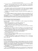
Figure 25.7 shows the image changes in each case.
Displaying Bit-Mapped Images
717
Figure 25.7
Horizontal and Vertical Bitmap Inversion with StretchBlt()
The StretchBlt() function requires two device contexts: one for the source
bitmap and another one for the destination. In this case we create a memory de
-
vice context and select the bitmap into it. This device context is the source rect
-
angle. The code also sets the stretch mode.
aMemDC = CreateCompatibleDC (hdc);
SelectObject (aMemDC, hstScope);
SetStretchBltMode (hdc, STRETCH_DELETESCANS);
All that is left is to display the bitmap using StretchBlt(). Once the bitmap is
blitted, the destination device context can be deleted. If the bitmap is not neces
-
sary, it can also be erased at this time.
StretchBlt(hdc, // Destination DC
0, 0, rect.right, rect.bottom, // dest. dimensions
aMemDC, // Source DC
0, 0, bm.bmWidth, bm.bmHeight, // Source dimensions
SRCCOPY);
DeleteDC (aMemDC);
718
Chapter 25
orignal bitmap vertical flip
horizontal flip vertical and horizontal flip