assembly language step by step programming with dos and linux PHẦN 7 doc
Bạn đang xem bản rút gọn của tài liệu. Xem và tải ngay bản đầy đủ của tài liệu tại đây (761.89 KB, 47 trang )
file:///D|/Agent%20Folders/Chapter%208%20Dividing%20and%20Conquering.htm
file:///D|/Agent%20Folders/Chapter%208%20Dividing%20and%20Conquering.htm (44 of 50) [9/26/2002 12:42:58 PM]
file:///D|/Agent%20Folders/Chapter%208%20Dividing%20and%20Conquering.htm
file:///D|/Agent%20Folders/Chapter%208%20Dividing%20and%20Conquering.htm (45 of 50) [9/26/2002 12:42:58 PM]
file:///D|/Agent%20Folders/Chapter%208%20Dividing%20and%20Conquering.htm
file:///D|/Agent%20Folders/Chapter%208%20Dividing%20and%20Conquering.htm (46 of 50) [9/26/2002 12:42:58 PM]
file:///D|/Agent%20Folders/Chapter%208%20Dividing%20and%20Conquering.htm
file:///D|/Agent%20Folders/Chapter%208%20Dividing%20and%20Conquering.htm (47 of 50) [9/26/2002 12:42:58 PM]
file:///D|/Agent%20Folders/Chapter%208%20Dividing%20and%20Conquering.htm
file:///D|/Agent%20Folders/Chapter%208%20Dividing%20and%20Conquering.htm (48 of 50) [9/26/2002 12:42:58 PM]
file:///D|/Agent%20Folders/Chapter%208%20Dividing%20and%20Conquering.htm
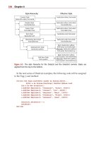
END Start ; The procedure named Start becomes the main program
You'll spot something odd in EAT5.ASM: instead of using ClrScr to clear the screen as I
have been for the last several incarnations of EAT, I've replaced ClrScr with a new
macro called Clear. Clear (defined in VIDLIB.MAC) uses some technology I haven't
explained yet, but will return to in Chapter 10. The lesson is that there are numerous ways
to skin a screen, and we've moved here from having the BIOS do it for us to doing it all
on our own. Take it on faith for now, until I come back to it. More to the point for the
current discussion is the use of the GotoXY and Write and Writeln macros.
Additionally, if you look closely at the main program procedure in EAT5.ASM,
file:///D|/Agent%20Folders/Chapter%208%20Dividing%20and%20Conquering.htm (49 of 50) [9/26/2002 12:42:58 PM]
file:///D|/Agent%20Folders/Chapter%208%20Dividing%20and%20Conquering.htm
something odd may occur to you: It's starting to look like something other than an
assembly-language program. This is true, and it's certainly possible to create so many
macros that your programs will begin to look like some odd high-level language.
The danger there is that unless you name your macros carefully, and document them both
in their macro-library files and on the lines where they are invoked, your programs will
not be any more comprehensible for their presence. Dividing complexity into numerous
compartments is only half the job— labeling the compartments is just as (or more)
important!
file:///D|/Agent%20Folders/Chapter%208%20Dividing%20and%20Conquering.htm (50 of 50) [9/26/2002 12:42:58 PM]
file:///D|/Agent%20Folders/Assembly%20Chap9%20Revised.htm
You don't take off until all your flight checks are made.
file:///D|/Agent%20Folders/Assembly%20Chap9%20Revised.htm (1 of 58) [9/26/2002 9:20:32 PM]
file:///D|/Agent%20Folders/Assembly%20Chap9%20Revised.htm
That's the reason that we haven't done a lot of instruction arranging in this book up until
now, here that we are on the third-to-last chapter. I've found that machine instructions
aren't the most important part of assembly-language programming. What's most
important is understanding your machine and your tools, and how everything fits
together. Higher-level languages like Pascal and Modula-2 hide much of those essential
details from you. In assembler you must see to them yourself. For some reason, authors
of previous "beginner" books on assembly language haven't caught on to this fact.
This fact (in fact) was the major motivation for my writing this book.
If you've digested everything I've said so far, however, you're ready to get in and
understand the remainder of the 8086/8088 instruction set. I won't teach it all in this
book, but the phrase "ready to understand" is germane. You can now find yourself a
reference and learn what instructions I don't cover on your own. The skills you need to
build programming skills are now yours, and if this book has accomplished that much, I'd
say it's accomplished a lot.
So let the fun begin.
9.1 Bits is Bits (and Bytes is Bits)
Assembly language is big on bits.
Bits, after all, are what bytes are made of, and one essential assembly-language skill is
building bytes and taking them apart again. A technique called bit mapping is widely
used in assembly language. Bit mapping assigns special meanings to individual bits
within a byte to save space and squeeze the last little drop of utility out of a given
amount of memory.
There is a family of instructions in the 8086/8088 instruction set that allow you to
manipulate the bits within the bytes by applying Boolean logical operations to the bytes
on a bit-by-bit basis. These bitwise logical instructions are: AND, OR, XOR, and NOT.
Another family of instructions allows you to slide bits back and forth within a single byte
or word. The most commonly used shift/rotate instructions are: ROL, ROR, RCL,
RCR, SHL, and SHR. (There are a few others that I will not be discussing in this book.)
Bit Numbering
Dealing with bits requires that we have a way of specifying which bits we're dealing
with. By convention, bits in assembly language are numbered, starting from 0, at the
file:///D|/Agent%20Folders/Assembly%20Chap9%20Revised.htm (2 of 58) [9/26/2002 9:20:32 PM]
file:///D|/Agent%20Folders/Assembly%20Chap9%20Revised.htm
least significant bit in the byte, word, or other item we're using as a bit map. The least
significant bit is the one with the least value in the binary number system. (Return to
Chapter 1 and reread the material on base 2 if that seems fuzzy to you.) It's also the bit on
the far right, if you write the value down as a binary number.
It works best as a visual metaphor. See Figure 9.1.
When you count bits, start with the bit on the right, and number them from 0.
"It's the Logical Thing to Do, Jim "
Boolean logic sounds arcane and forbidding, but remarkably, it reflects the realities of
ordinary thought and action. The Boolean operator AND, for instance, pops up in many
of the decisions you make every day of your life. For example, to write a check that
doesn't bounce, you must have money in your checking account AND checks in your
checkbook. Neither alone will do the job. ("How can I be overdrawn?" goes the classic
question, "I still have checks in my checkbook!) You can't write a check you don't have,
and a check without money behind it will bounce. People who live out of their
checkbooks (and they always end up ahead of me in the checkout line at Safeway) must
use the AND operator frequently.
When mathematicians speak of Boolean logic, they manipulate abstract values called
file:///D|/Agent%20Folders/Assembly%20Chap9%20Revised.htm (3 of 58) [9/26/2002 9:20:32 PM]
file:///D|/Agent%20Folders/Assembly%20Chap9%20Revised.htm
true and false. The AND operator works like this. Condition l AND Condition 2 will be
considered true if both Condition l and Condition 2 are true. If either condition is false,
the result will be false.
There are in fact four different combinations of the two input values, so logical
operations between two values are usually summarized in a form called a truth table. The
truth table for the AND operator is shown in Table 9.1.
There's nothing mysterious about the truth table. It's just a summary of all possibilities of
the AND operator as applied to two input conditions. The
The AND Instruction
The AND instruction embodies this concept in the 8086/8088 instruction set. The AND
instruction performs the AND logical operation on two bytes or two words (depending
on how you write the instruction) and replaces its first operand with the result of the
operation. (By first, I mean the operand closest to the mnemonic.) In other words, if you
write this instruction
AND AL, BL
the CPU will perform a gang of eight bitwise AND operations on the 8 bits in AL and
BL. Bit 0 of AL is ANDed with bit 0 of BL, bit 1 of AL is ANDed with bit 1 of BL, and
file:///D|/Agent%20Folders/Assembly%20Chap9%20Revised.htm (4 of 58) [9/26/2002 9:20:32 PM]
file:///D|/Agent%20Folders/Assembly%20Chap9%20Revised.htm
so on. Each AND operation generates a result bit, and that bit is placed in the first
operand (here, AL) after all eight AND operations occur. This is a common thread
among machine instructions that perform some operation on two operands and produce a
result: the result replaces the first operand.
Masking Out Bits
A major use of the AND instruction is to isolate one or more bits out of a byte value or a
word value. The term isolate here simply means to set all unwanted bits to a reliable 0
value. As an example, suppose we are interested in testing bits 4 and 5 of a value to see
what those bits are. To do that, we have to be able to ignore the other bits (bits 0 through
3 and 6 through 7) and the only way to safely ignore bits is to set them to 0.
AND is the way to go. We set up a bit mask in which the bit numbers that we want to
inspect and test are set to 1, and the bits we wish to ignore are set to 0. To mask out all
bits but bits 4 and 5, we must set up a mask in which bits 4 and 5 are set to 1, with all
other bits at 0. This mask in binary is 00110000B, or 30H in hex. (To verify it, count the
bits from the right hand end of the binary number, starting with 0.) This bit mask is then
ANDed against the value in question. Figure 9.2 shows this operation in action, with the
30H bit mask just described, and an initial value of 9DH.
The three binary values involved are shown laid out vertically, with the LSB (the right-
hand end) of each value at the top. You should be able to trace each AND operation and
verify it by looking at Table 9.2.
The end result is that all bits except 4 and 5 are guaranteed to be 0 and can thus be safely
ignored. Bits 4 and 5 could be either 0 or 1. (That's why we need to test them; we don't
know what they are.) With the initial value of 9DH, bit 4 turns out to be a 1, and bit 5
turns out to be a 0. If the initial value were something else, bits 4 and 5 could both be 0,
both 1, or some combination of the two.
Don't forget: the result of the AND operation replaces the first operand after the
operation is complete.
file:///D|/Agent%20Folders/Assembly%20Chap9%20Revised.htm (5 of 58) [9/26/2002 9:20:32 PM]
file:///D|/Agent%20Folders/Assembly%20Chap9%20Revised.htm
For an example of the AND instruction in operation isolating bits in a word, look ahead
to the Byte2Str procedure .
The OR Instruction
Closely related to the AND logical operation is OR, which, like the AND logical
operation, has an embodiment with the same name in the 86-family instruction set.
Structurally, the OR instruction works identically to AND. Only its truth table is
different: while AND requires that both its operands be 1 for the result to be 1, OR is
satisfied that at least one operand has a 1 value. The truth table for OR is shown in Table
9.3.
Because it's unsuitable for isolating bits, OR is used much more rarely than AND
file:///D|/Agent%20Folders/Assembly%20Chap9%20Revised.htm (6 of 58) [9/26/2002 9:20:32 PM]
file:///D|/Agent%20Folders/Assembly%20Chap9%20Revised.htm
.
The XOR Instruction
In a class by itself is the exclusive OR operation, embodied in the XOR instruction.
XOR, again, does in broad terms what AND and OR do: it performs a logical operation
on two operands, and the result replaces the first operand. The logical operation,
however, is exclusive or, meaning that the result is 1 only if the two operands are
different. (1 and 0 or 0 and 1.) The truth table for XOR should make this slippery notion
a little clearer (see Table 9.4).
Look this over carefully! In the first and last cases, where the two operands are the same,
the result is 0. In the middle two cases, where the two operands are different, the result is
1.
Some interesting things can be done with XOR, but most of them are a little arcane for a
beginner's book. I will show you one handy XOR trick, however: "XORing" any value
against itself yields 0. Furthermore, putting 0 in a register by XORing the register against
itself is faster than putting a 0 in the register by MOVing in a 0 as immediate data.
That is, both of these instructions accomplish the same thing:
mov AL,0
xor AL,AL
file:///D|/Agent%20Folders/Assembly%20Chap9%20Revised.htm (7 of 58) [9/26/2002 9:20:32 PM]
file:///D|/Agent%20Folders/Assembly%20Chap9%20Revised.htm
However, if you're running an 8086 or 8088 processor, the first instruction uses four
machine cycles, while the second uses only three. That's not a tremendous difference
(though purists will argue that it represents a 25% improvement) but there are times in
assembly language where every machine cycle counts!
How this trick works should be clear from reading the truth table, but to drive it home
I've laid it out in Figure 9.3.
Follow each of the individual XOR operations across the figure to its result value.
Because each bit in AL is XORed against itself, in every case the XOR operations
happen between two operands that are identical. Sometimes both are 1, sometimes both
are 0, but in every case the two are the same. With the XOR operation, when the two
operands are the same, the result is always 0. Voila! 0 in a register in three cycles flat.
The NOT Instruction
Easiest to understand of all the bitwise logical instructions is NOT. The truth table for
the NOT instruction (Table 9.5) is pretty simple because NOT only takes one operand.
And what it does is simple as well: NOT takes the state of each bit in its single operand
and changes it to its opposite state. What was 1 becomes 0 and what was 0 becomes 1.
file:///D|/Agent%20Folders/Assembly%20Chap9%20Revised.htm (8 of 58) [9/26/2002 9:20:32 PM]
file:///D|/Agent%20Folders/Assembly%20Chap9%20Revised.htm
Segment Registers Don't Respond to Logic!
One limitation of the segment registers CS, DS, SS, and ES is that they cannot be used
with any of the bitwise logical instructions. If you try, the assembler will hand you an
"Illegal use of segment register" error. If you need to perform a logical operation on a
segment register, you must first copy the segment register's value into one of the
nonsegment registers (AX, BX, CX, DX, BP, SI, and DI); perform the logical operation
on the new register, and then copy the result back into the segment register.
Table 9.5. The NOT truth table
Bit Operator Result bit
0 XOR 1
file:///D|/Agent%20Folders/Assembly%20Chap9%20Revised.htm (9 of 58) [9/26/2002 9:20:32 PM]
file:///D|/Agent%20Folders/Assembly%20Chap9%20Revised.htm
1 XOR 0
9.2 Shifting Bits
The other way of manipulating bits within a byte is a little more straightforward: you
shift the bits to one side or the other. There are a few wrinkles to the process, but the
simplest shift instructions are pretty obvious: the SHL instruction Shifts its operand
Left, whereas the SHR instruction Shifts its operand Right.
All of the shift instructions (including the slightly more complex ones I'll describe a little
later) have the same general form, illustrated here by the SHL instruction:
SHL <register/memory>,<count>
The first operand is the target of the shift operation; that is, the value that you're going to
be shifting. It can be register data or memory data, but not immediate data. The second
operand specifies the number of bits by which to shift.
Shift by What?
The <count> operand is a little peculiar. It can be one of two things: the literal digit 1, or
else the register CL. (Not CX!) If you specify the count as 1, then the shift will be by one
bit. If you wish to shift by more than one bit at a time, you must load the shift count into
register CL. Counting things is CX's (and hence CL's) hidden agenda; it counts shifts,
loops, string elements, and a few other things. That's why it's sometimes called the count
register ("C" for "count").
Although you can load a number as large as 255 into CL, it really only makes sense to
use count values up to 16. If you shift any bit in a word by 16, you shift it completely out
of the word!
Something to keep in mind: moving an immediate count value into CL takes some time.
Furthermore, executing a shift instruction that takes its count value from CL takes more
time to execute than executing a shift instruction that uses the literal 1 as its count value.
These two facts conspire to make it faster to use successive shift-by-1 instructions unless
you need to shift by 5 or more bits.
As an example, consider the following instruction sequence, which is what must be done
to use CL to shift a word by 3 bits:
file:///D|/Agent%20Folders/Assembly%20Chap9%20Revised.htm (10 of 58) [9/26/2002 9:20:32 PM]
file:///D|/Agent%20Folders/Assembly%20Chap9%20Revised.htm
MOV CL,3
SHL SI,CL
Most remarkably, it is faster to accomplish the same shift this way:
SHL SI,1
SHL SI,1
SHL SI,1
The rule of thumb is this: unless you need to shift by more than 4 bits, use consecutive
shift-by-1 instructions rather than shifting via the CL register.
How Bit Shifting Works
Understanding the shift instructions requires that you think of the numbers being shifted
as binary numbers, and not hexadecimal or decimal numbers. (If you're fuzzy on binary
notation, again, take another slip through Chapter 1.) A simple example would start with
register AX containing a value of OB76FH. Expressed as a binary number (and hence as
a bit pattern) OB76FH is
1011011101101111
Keep in mind that each digit in a binary number is 1 bit. If you execute an SHL AX,1
instruction, what you'd find in AX after the shift is the following:
0110111011011110
A 0 bit has been inserted at the right hand end of the number, and the whole shebang has
been bumped toward the left by one digit. Notice that a 1 bit has been bumped off the left
end of the number into nothingness.
Bumping Bits into the Carry Flag
Well, not exactly nothingness. The last bit shifted out is bumped into a temporary
bucket for bits the Carry flag (CF). The Carry flag is one of those odd bits lumped
together as the Flags register, which I described in Section 6.4. You can test the state of
file:///D|/Agent%20Folders/Assembly%20Chap9%20Revised.htm (11 of 58) [9/26/2002 9:20:32 PM]
file:///D|/Agent%20Folders/Assembly%20Chap9%20Revised.htm
the Carry flag with a branching instruction, as I'll explain in Section 9.3.
Keep in mind when using shift instructions, however, that, in addition to the Shift
instructions, a lot of different instructions, including the bitwise logical instructions and
the arithmetic instructions, use the Carry flag. If you bump a bit into the Carry flag with
the intent of testing that bit to see what it is, test it before you execute another instruction
that affects the Carry flag.
If you shift a bit into the Carry flag and then immediately execute another shift
instruction, the first bit will be bumped off the end of the world and into nothingness.
The Byte2Str Procedure: Converting Numbers to Displayable Strings
As we've seen, DOS has a fairly convenient method for displaying text on your screen.
The problem is that it only displays text—if you want to display a numeric value from a
register as a pair of digits, DOS won't help. You first have to convert the numeric value
into its string representation, and then display the string representation through DOS.
Converting hexadecimal numbers to hexadecimal digits isn't difficult, and the routine to
do the job demonstrates several of the new concepts we're exploring in this chapter. Read
the Byte2Str procedure carefully:
To call Byte2Str you must pass the value to be converted to a string in AL, and the
address of the string into which the string representation is to be stored as DS:SI.
Typically, DS will already contain the segment address of your data segment, so you
most likely will only need to pass the offset of the start of the string in SI.
In addition to the code shown here, Byte2Str requires the presence of a second string in
the data segment. This string, whose name must be Digits, contains all 16 of the digits
used to express hexadecimal numbers. The definition of Digits looks like this:
Digits DB '0123456789ABCDEF'
The important thing to note about Digits is that each digit occupies a position in the
string whose offset from the start of the string is the value it represents. In other words,
'0' is at the start of the string, zero bytes offset from the string's start. The character "7"
lies seven bytes from the start of the string, and so on. Digits is what we call a look up
table and it represents (as I'll explain below) an extremely useful mechanism in assembly
language.
file:///D|/Agent%20Folders/Assembly%20Chap9%20Revised.htm (12 of 58) [9/26/2002 9:20:33 PM]
file:///D|/Agent%20Folders/Assembly%20Chap9%20Revised.htm
Splitting a Byte into Two Nybbles
Displaying the value stored in a byte requires two hexadecimal digits. The bottom four
bits in a byte are represented by one digit (the least significant, or rightmost digit) and the
top four bits in the byte are represented by another digit (the most significant, or leftmost
digit.) Converting the two digits must be done one at a time, which means that we have
to separate the single byte into two four-bit quantities, which are often called nybbles.
file:///D|/Agent%20Folders/Assembly%20Chap9%20Revised.htm (13 of 58) [9/26/2002 9:20:33 PM]
file:///D|/Agent%20Folders/Assembly%20Chap9%20Revised.htm
To split a byte in two, we need to mask out the unwanted half. This is done with an AND
instruction. Note in the Byte2Str procedure that the first instruction, MOV DI,AX,
copies the value to be converted (which is in AL) into DI. You don't need to move AH
into DI here, but there is no instruction to move an 8-bit register-half like AL into a 16-
bit register like DI. AH comes along for the ride, but we really don't need it. The second
instruction masks out the high twelve bits of DI using AND. This eliminates what had
earlier been in free-rider AH, as well as the high four bits of AL. What's left in DI is all
we want: the lower four bits of what was originally passed to the routine in AL.
Using a Lookup Table
The low nybble of the value to be converted is now in DI. The address of Digits is
loaded into BX. Then the appropriate digit character is copied from Digits into AH. The
whole trick of using a lookup table lies in the way the character in the table is addressed:
mov AH,BYTE PTR [BX+DI]
DS:BX points to the start of Digits, so [BX] would address the first character in digits.
To get at the desired digit, we must index into the lookup table by adding the offset into
the table to BX. There is an 8086/8088 addressing mode intended precisely for use with
lookup tables, called base indexed addressing. That sounds more arcane than it is; what it
means is that instead of specifying a memory location at [BX], we add an index to BX,
and address a memory location at [BX+DI].
If you recall, we masked out all of DI except the four lowest bits of the byte we are
converting. These bits will contain some value from 0 through OFH. Digits contains the
hexadecimal digit characters from 0 through F. By using DI as the index, the value in DI
will select its corresponding digit character in Digits. We are using the value in DI to
look up its equivalent hexadecimal digit character in the lookup table (Digits). See
Figure 9.4.
So far, we've read a character from the lookup table into AH. Now, we use yet another
addressing mode to move the character from AX back into the second character of the
destination string, whose address was passed to Byte2Str in DS:SI. This addressing
mode is called indirect addressing, though I question the wisdom of memorizing that
term. The mode is nothing more than indirect addressing (addressing the contents of
memory at [SI]) with the addition of a literal displacement:
mov [SI+1],AH
file:///D|/Agent%20Folders/Assembly%20Chap9%20Revised.htm (14 of 58) [9/26/2002 9:20:33 PM]
file:///D|/Agent%20Folders/Assembly%20Chap9%20Revised.htm
This looks a lot like base indexed addressing (which is why the jargon may not be all that
useful) with the sole exception that what is added to SI is not a register but a literal
constant.
Once this move is done, the first of the two nybbles passed to Byte2Str in AL has been
converted to its character equivalent and stored in the destination string variable at
DS:SI.
Now we have to do it again, this time for the high nybble.
Shifting the High Nybble into the Low Nybble
The high nybble of the value to be converted has been waiting patiently all this time in
AL. We didn't mask out the high nybble until we moved AX into DI, and did our
masking on DI instead of AX. So AL is still just as it was when Byte2Str began.
The first thing to do is clear AH to 0. Byte2Str uses the XOR AH,AH trick I described
in the last section. Then we move AX into DI.
All that remains to be done is to somehow move the high nybble of the low byte of DI
into the position occupied by the low nybble. The fastest way to do this is simply to shift
DI to the right—four times in a row. This is what the four SHR instructions in Byte2Str
do. The low nybble is simply shifted off the edge of DI, into the Carry flag, and then out
into nothingness. After the four shifts, what was the high nybble is now the low nybble,
and once again, DI can be used as an index into the Digits lookup table to move the
appropriate digit into AH.
Finally, there is the matter of storing the digit into the target string at DS:SI. Notice that
this time, there is no +1 in the MOV instruction:
mov [SI],AH
Why not? The high nybble is the digit on the left, so it must be moved into the first byte
in the target string. Earlier, we moved the low nybble into the byte on the right. String
indexing begins at the left and works toward the right, so if the left digit is at index 0 of
the string, the right digit must be at index 0+1.
Byte2Str does a fair amount of data fiddling in only a few lines. Read it over a few times
while following the above discussion through its course until the whole thing makes
sense to you.
FIGURE 9.4
file:///D|/Agent%20Folders/Assembly%20Chap9%20Revised.htm (15 of 58) [9/26/2002 9:20:33 PM]
file:///D|/Agent%20Folders/Assembly%20Chap9%20Revised.htm
Converting Words to Their String Form
Having converted a byte-sized value to a string, it's a snap to convert 16-bit words to
their string forms. In fact, it's not much more difficult than calling Byte2Str twice:
The logic here is fairly simple—if you understand how Byte2Str works. Moving AX
into CX simply saves an unmodified copy of the word to be converted in CX. Something
to watch out for here: if Byte2Str were to use CX for something, this saved copy would
be mangled, and you might be caught wondering why things weren't working correctly.
This is a common enough bug for the following reason: you create Byte2Str, and then
create Word2Str to call Byte2Str. The first version of Byte2Str does not make use of
CX, so it's safe to use CX as a storage bucket.
file:///D|/Agent%20Folders/Assembly%20Chap9%20Revised.htm (16 of 58) [9/26/2002 9:20:33 PM]
file:///D|/Agent%20Folders/Assembly%20Chap9%20Revised.htm
However—later on you beef up Byte2Str somehow, and in the process add some
instructions that use CX. You plumb fergot that Word2Str stored a value in CX
whileWord2Str was calling
Byte2Str
. It's pointless arguing whether the bug is that Byte2Str uses CX, or that Word2Str
assumes that no one else is using CX. To make things work again, you would have to
stash the value somewhere other than in CX. Pushing it onto the stack is your best bet if
you run out of registers. (You might hit on the idea of stashing it in an unused segment
register like ES—but I warn against it! Later on, if you try to use these utility routines in
a program that makes use of ES, you'll be in a position to mess over your memory
addressing royally. Let segment registers hold segments. Use the stack instead.)
Virtually everything that Word2Str does involves getting the converted digits into the
proper positions in the target string. A word requires four hexadecimal digits altogether.
In a string representation, the high byte occupies the left two digits, and the low byte
occupies the right two digits. Since strings are indexed from the left to the right, it makes
a certain sense to convert the left end of the string first.
This is the reason for the XCHG instruction. It swaps the high and low bytes of AX, so
that the first time Byte2Str is called, the high byte is actually in AL instead of AH.
file:///D|/Agent%20Folders/Assembly%20Chap9%20Revised.htm (17 of 58) [9/26/2002 9:20:33 PM]
file:///D|/Agent%20Folders/Assembly%20Chap9%20Revised.htm
(Remember that Byte2Str converts the value passed in AL.) Byte2Str does the
conversion and stores the two converted digits in the first two bytes of the string at
DS:SI.
For the second call to Byte2Str, AH and AL are not exchanged. Therefore the low byte
will be the one converted. Notice the following instruction:
add SI,2
This is not heavy-duty math, but it's a good example of how to add a literal constant to a
register in assembly language. The idea is to pass the address of the second two bytes of
the string to Byte2Str as though they were actually the start of the string. This means that
when Byte2Str converts the low byte of AX, it stores the two equivalent digits into the
second two bytes of the string.
For example, if the high byte was 0C7H, the digits C and 7 would be stored in the first
two bytes of the string, counting from the left. Then, if the low byte were 042H, the
digits 4 and 2 would be stored at the third and fourth bytes of the string, respectively. The
whole string would read C742 when the conversion was complete.
As I've said numerous times before: understand memory addressing and you've got the
greater part of assembly language in your hip pocket. Most of the trick of Byte2Str and
Word2Str lies in the different ways they address memory. As you study them, focus on
the machinery behind the lookup table and target string addressing. The logic and shift
instructions are pretty obvious and easy to figure out by comparison.
9.3 Flags, Tests, and Branches
Those assembler-knowledgeable folk who have stuck with me this long may be
wondering why I haven't covered conditional jumps until this late in the book. I mean,
we've explained procedures already, and haven't even gotten to jumps yet.
Indeed. That's the whole point. I explained procedures before jumps because
when people learn those two concepts the other way around, they have a tendency
to use jumps for everything, even when procedures are called for. Unlike some high-level
languages like Pascal and Modula-2, there is no way around jumps—(what they so
derisively call "GOTOs")—in assembly language. Sadly, some people then assume that
jumps are "it," and don't bother imposing any structure at all on their assembly-language
programs. By teaching procedures first, I feel that I've at least made possible a more
balanced approach on the part of the learner.
file:///D|/Agent%20Folders/Assembly%20Chap9%20Revised.htm (18 of 58) [9/26/2002 9:20:33 PM]