Industrial Brushless Servomotors Episode 3 docx
Bạn đang xem bản rút gọn của tài liệu. Xem và tải ngay bản đầy đủ của tài liệu tại đây (971.12 KB, 20 trang )
The brushless machine
$$
0 90 180 270 360
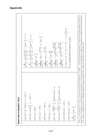
Figure
2.5
Torque from a simple brushless
motor
The peak torque at positions 1 and 3 in Figures 2.5 and 2.6 is
equivalent to the steady output torque of the two-pole brushed
motor already described in Figure 1.3. The average torque
constant of this particular brushless machine is therefore only
half that of the brushed motor. The ripple in the output
torque can be described as 100% and would be unacceptable
Industrial
Brushless Servomotors
2.2
36
in most servomotor applications. The problem arises when the
poles are halfway between one side of the winding and the
other, where the net force is zero. We will see shortly how
the use of three windings eliminates such nulls to produce a
theoretically constant output.
0 90 180 270 0 360
,,
, J
0 Rotor angle (O) 360
Figure 2.6
Torque and back
emf for
a single-winding
brushless motor
Back emf
Rotating flux sweeps across the stator winding to produce a
back emf with an average half-cycle value of
E=KEw
where KE is half the value of the voltage constant of the brushed
machine of Figure 1.3. The back emf alternates in direction as
the poles of the magnet change position, as shown in Figure
2.6. It is important to note that the back emfat the input
terminals of the brushless motor alternates in direction, as
does the direct current input. The motor has the same
construction as an AC synchronous motor, which normally
has a sinusoidal rather than rectangular current waveform.
The brushless machine 37
Although the single-phase brushless machine works correctly as
a motor, its output torque is 'lumpy' and would be unsuitable
for most industrial servomotor applications. The main uses
occur at the low power end of the scale where the brushless
motor is manufactured with a single winding in very large
numbers, for example as fan motors for the cooling of
electronic equipment. These are normally exterior-rotor
motors, where the fan is mounted on a hollow, cylindrical
permanent magnet which rotates around a laminated,
cylindrical stator with slots for the winding.
2.3 The three-winding brushless motor
Most industrial brushless servomotors have three windings,
which are normally referred to as phase windings. There are
two main types. One is known as the
squarewave
motor, the
name being derived from the (theoretically) rectangular
waveform of the current supplied to its windings. The other
is supplied with sinusoidal AC and is known as the
sinewave
motor. Both types are physically very similar to the three-
phase AC synchronous motor.
The squarewave motor
The windings of the ideal squarewave motor would be supplied
with currents in the form of perfectly rectangular pulses, and
the flux density in the air gap would be constant around the
pole faces. The squarewave version of the small four-pole
motor in Figure 2.3 would have the cylindrical magnet rotor
shown in Figure 2.1. Figure 2.7 shows a simple layout for a
two-pole machine where each of the three windings, a, b, c, is
divided into two coils connected in series; for example, coils
bl and b2 are connected in series to form winding b. The start
and finish of, for example, coil bl are marked bl and bl'. The
two coils of each winding have an equal number of turns and
are mechanically spaced apart by 30 ~ around the stator.
38 Industrial Brushless Servomotors
2.3
al
a'l
Figure 2.7
Two-pole, three-phase motor with two slots per phase, per
pole
The effect of distributing each winding into more than one slot
is to extend the arc over which the winding is influenced by
each pole as the rotor turns. This means that the number of
slots should be specified in relation to the number of poles as
well as to the number of windings. The stator in Figure 2.7 is
symmetrical, with three windings, 12 slots and six coils each
with an equal number of turns. As a result, each phase will
provide the same magnitude of torque and back emf.
Torque production per phase
Figure 2.8 shows how the a-phase torque is produced in the
squarewave motor when the current has the ideal rectangular
waveform shown. The method of supplying the current and
its commutation between the phases is described in Chapter
3. The flux density waveform around the pole faces has not
been shown in a rectangular form. Changes in flux direction
are less abrupt due to the skewing of the stator slots, and the
flux waveform is shown in the diagram with ramp leading
and trailing edges as a first approximation. In practice the
corners are rounded due to fringing effects near the edges of
The brushless machine 39
the poles. Rotation is anticlockwise and the coincidence of the
pole divisions with the first coil has been chosen as the starting
point. The flux direction is drawn for the N-pole, and the
current direction for the upper coil sides in the diagram.
As the rotor moves from the 0 = 0 ~ position, N-pole flux starts
to cross the upper side of the first coil, and when 0 = 30 ~ the
second coil comes under the same influence. The lower sides a'
of the coils are similarly affected by the S-pole flux. As the
rotor turns through 180 ~ , the flat topped section of the flux
wave moves across the full winding over a window of 120 ~
This is the period when the current must be fed in from an
electronically controlled supply. Positive torque is produced as
the current flows through the winding. The cycle is completed
as 0 changes from 180 ~ to 360 ~ again producing positive torque.
Magnitudes of back emf and torque per phase
The 'ac' nature of the back emf is evident in Figure 2.8. When
the fiat topped part of the flux wave sweeps across the coils of
the 'a' phase, the voltage generated across one side of one turn
of either coil is
et= Blrw
where the speed of rotation is w rad s -1, and l is the length of
the coil side (into the paper). The voltage generated around a
complete turn is
2e'= 2Blrw
If the winding has Nph turns distributed between the two coils,
the total back emf generated around the two series-connected
coils is
ea 2NphBlrw
The torque produced by one side of one turn of either coil is
t' = Bliar
and the total a-phase torque is
ta = 2NphBlia r
40
Industrial Brushless Servomotors
2.3
Figure
2.8
Torque and backemf for the'a'phase
The brushless machine
41
The three windings are symmetrically distributed around the
stator, as are the magnetic poles around the rotor, and so
ea eb
ec
and
ta lb lc
Before combining these quantities to give the output torque
and the back emf at the input terminals, we should first look
at how the motor windings are connected together.
Wye (Y) and delta (A) connections
Figure 2.9(a) shows the Y or star connection, where the
windings are joined to form a star point. The figure also
shows the motor currents which flow from an electronically
controlled source. Each winding of the star is in series with
its supply line, and the same current flows in the line and the
winding. One full cycle of each phase current must occur for
every 360 ~ of rotor movement and so ib and ic are displaced
from ia by 0 120 ~ and 240 ~ Note that the sum of the three
currents at the star point is zero for all values of 0. Note also
that the emf across a pair of motor terminals is the difference
(for the chosen reference directions) of the emfs across the
respective phase windings.
Figure 2.9(b) shows the A connection, where the emf across the
windings appears across the motor terminals. The line currents
are the same as before but differ here from the phase currents.
The difference between any two phase currents equals the line
current flowing to the common point of the two windings.
The line-to-line voltages are no longer trapezoidal, and the
phase emfs do not sum to zero. Circulating currents are likely
around the closed delta path, with the possibility of motor
overheating due to the extra
i2R
losses. The A connected
stator is therefore less useful and most squarewave motors
are made with the Y connection.
42 Industrial Brushless Servomotors 2.3
I , I I
I I ~('~
!
i
i
i
, i
i
I I : !
!
!
!
!
!
!
i
i
i
i
I I
~ib i c
eab I< e b
=ea-eb
I
iab
ec
Figure 2.9
Effect of motor connections on phase currents and voltages
n
The brushless machine 43
Three-phase torque and back emf
Figure 2.10 shows the patterns of ideal torque and emf for each
of the three windings of a Y-connected squarewave motor with
the winding and pole layout described in Figure 2.8. The
squarewave motor is often referred to as the 'trapezoidal'
motor in view of the trapezoidal shape of the back emf. The
emf across the a-b input terminals in Figure 2.9(a) is
eab : ea eb
and so the peak emf in Figure 2.10 is
or
eab 2ea
e,b = 4NphBlroJ
The back emf across a pair of machine terminals is
eab ebc = eta =
E
=
KEW
where KE =
4NphBlr,
the voltage constant of the motor.
Looking now at the patterns of torque produced by the
motor, we see that each phase works for 240 ~ and rests for
the remaining 120 ~ of each turn of the rotor. However, the
combined effort of the three phases does produce
the extremely important feature of a theoretically smooth
output torque. Only two phases produce torque at any one
time and so the motor torque is
or
T = 2ta
T = 4NphBllr
where I is the line current input to the motor. The torque can
be written in the familiar form
T= KTI
where
Kx = 4NphBlr,
the torque constant of the motor.
4~ Industrial Brushless Servomotors 2.3
Comparison between the emf and torque expressions confirms
that the voltage and torque constants are equal for the
squarewave motor. As in the case of the brushed motor, the
numerical equivalence exists only when the constants are
expressed in SI units.
eo
0
eb
0
er
0
0 60 120 180 240 300 e 360
, , , i ,, ,
" F " I I - I i I l I "'I' I I I
I I I I I I
I I I I I I I I I I
L = J t _ k,,~
t
I
l J ! _- !
' ' ' ; ' ,~~.' ' ' '/-I
, , , , , , , , , , , ,
I I I I I I I ! I 1 I I
I I I I I I I I I I I I
I I I I I/' I I' ''I l " ~I l I
I I I I ~ I I I I ~ I I
i ' 9 '! i " ! ! 'l "I
" I i/ i ~' ' ~,~ i.i ' l
t I I / I ! i I I I '1,~ 1
s -,,,,,_j
l I I I I I I I I
I I I I I I I 1 I I I I
1 I I I I i I I I I I I
t ~ I I I I I I / I I
_ l . l I , _I_ l l , . , l
l l ~,1 , " l , , ~ l l l 1
I I "~, X I'~ I I I I /i ~I ' I I I I
,
i J J i , l , i ~ , i
t. , I~~ , , ~~.I ,
I ' I I I I '~I 1 I I I I "1
l I l , , , , l ~I I
I I I I I I I I I I I I
lb ~'~~t l'~'::~:~":~'~
- ~:
:~ -
~ : -=. i ,, ,j ,~1 -,,; , -,~- y ~ J,I ,ll iI
[ ' , -' 9 _l , I I ' I , L ,
I I I I I I I I I I I I
| I I I 1 I I - I I I I - 1 I
, _ _ ' ' . , " I ,, L ~ , I
o, -i , -',, ': "
I ~ ~,;'-' ' ~ ~ -~',~ ' ' ~/"~' '
L t i _ L_ ~ ,t i ~ 1 I ,I 9 L J
0 180 e 360
Figure 2.10
Emf and torque for aY-connected squarewave motor
The brushless machine 4.$'
Practical emf and torque waveforms
The smoothness of the rotor output torque is affected by
fringing effects which leave less than 120 ~ of the flux wave in
a flat-topped form. This is in addition to the effect of the
ripple in the flat top caused by stator slotting. Further
irregularities in the output torque result from stator current
waveforms which are never perfectly rectangular in practice.
The sinewave motor
The ideal squarewave motor has rectangular waveforms of flux
density and input current, and has windings concentrated in
coils in the stator slots. The ideal sinewave motor has
sinusoidal flux and current waveforms and a sinusoidal
distribution of its windings.
Sinusoidal AC input current
In common with squarewave motors, most sinewave machines
are made with three phases. Figure 2.11 (a) shows the three line
currents which are supplied to the motor from an electronic
inverter.
Sinusoidal
flux
density in the air gap
There are a number of ways in which the magnetic circuit can
be designed to produce a near sinusoidal flux density
waveform. A good sinewave can be achieved by tapering the
magnets towards the edges as shown in Figure 2.1 l(b). The
taper of the profile is exaggerated in the diagram. Formation
of the waveform is assisted by fringing effects which are
encouraged by the use of a relatively small pole arc. Figure
2.1 shows a four-pole, sinusoidal rotor where the tapered
magnets are mounted on a square section hub.
Sinusoidal winding distribution
The ideal, fully distributed layout of stator conductors for one
phase of a two-pole, sinusoidal motor is represented in Figure
46 Industrial Brushless Servomotors
2.3
2.11(c). In practice an irregularity must be present in the
distribution due to the bunching of conductors in slots.
The three-phase sinewave motor closely resembles the three-
phase AC synchronous motor and its characteristics can be
found through the phasor diagram method. However, its
ideal torque and back emf can still be found by the method
we have used for the squarewave machine. Figure 2.12 shows
one phase of a two-pole sinewave motor with ideal flux,
current and winding distributions. There are Ns conductors
on each side of the winding of Ns turns. The reference has
been chosen at the moment when the N-S pole axis of the
rotor lies horizontally in the diagram, when 0 = 0 and the
input current is zero. We assume that the current is
controlled (externally) in such a way that it varies
sinusoidally with rotor angle 0. Note that the current
magnitude varies with 0 and not with stator angle 4~. The
diagram is drawn for a moment in time when 0 = 90 ~ and
the conductor current is therefore at its maximum of Iu.
Back emf
When 0 = 90 ~ the emf across a conductor of length I at stator
angle 4~ is
or
el : Blv
el - BM sin ~b
lrw
The combined emf across the conductors within dO is
Ns.
ed~ - -~-
sm ~ d~b BM sin ~b
lrw
or
Ns
edO -~- BM lrw
sin 2 ~b d~b
Integrating this expression over 4~ = 0 to 7r gives the total back
emf across Ns conductors as
7r
EM -~ NsBM lrw
The brushless machine 47
DC
(a)
J I I I I I I
i.~ '
I t I
[ i J
I I I I I I I
I I I I I I
I i~ t I
.~-w"FI I i
I I I I I I
I I I I ! t I
I i I I I I
(b)
Ns tL
(c)
Ns sin ~ d~ conductors
Figure 2.11
Main features of the sinewave brushless motor
411
Industrial Brushless Servomotors
2.3
EM is the peak back emf, generated at the moment when flux
cutting is at a maximum. The peak emf for the full winding,
which has 2Ns conductors, is 2EM. The conductors are swept
by a sinusoidally distributed flux and the variation of back
emf with time must also be sinusoidal. The rms value of the
emf across the full winding is therefore
or
2EM
7r
Eph
2 2x/~ sBMlr"~
For a Y-connected sinewave motor, the back emfs across the
three individual windings form a balanced set of three-phase
voltages. The rms emf which appears across the motor input
terminals and supply lines will therefore be x/3Eph, or
E- ~NsBMlrw = grw
Torque
When 0- 90 ~ the force on a conductor at stator angle ~b is
f BIIM
or
f= BM sin
dpllM
The combined force on the conductors within d~b is
Ns N~ BMIM l sin 2 ~b d~b
fd~ - -~-sin ~b d~b BM sin ~b
llM -~-
Integrating over ~b = 0 to 27r, the total force on the full winding
of 2Ns conductors at the moment when 0 = 90 ~ is found to be
71"
FM = NSSM/M/
Figure 2.12 is drawn for the moment when the force on the
winding is at a maximum. The rotor experiences an equal
and opposite reaction to give a peak output torque of
The
brushless machine 49
= Conductors
B(O=90 ~
/(0=90 ~
I I
I I
I I
I
IM 1
i
I I
I
/tl
2n|
I I
/MI I .
I I
I I
I
"" "'0
- _ie
Figure 212
Flux density and phase current in the 2pole sinewave motor
71"
TM ~ NsBM IM lr
TM is the torque when the rotor pole axis lies at an angle of 90 ~
to the chosen reference position. When the rotor axis lies at 0 to
the reference, the stator current is 1M sin/9 and the flux density
effective over the full winding is BM sin0. The torque becomes
Industrial Brushless Servomotors 2.3
$O
To - TM
sin20
To
is always positive and varies
position, as shown in Figure 2.13.
sinusoidally with rotor
To
TM
180 360
Figure 2.13
Torque
from one phase of a sinewave motor
Three-phase
torque
and emf
The three-phase sinewave motor has three of the single-phase
windings shown in Figure 2.12. The axis of each winding is
120 ~ from the other two, around the stator. The waveforms
of torque against 0 produced by the three phases will
therefore be separated by the same angle. The contribution of
each phase to the overall torque is shown in Figure 2.14. The
torque produced by each phase varies sinusoidally around its
average value. When the three waveforms are added together,
the sinusoidal components cancel out and we are left with the
sum of the averages as the constant value of the torque on
the rotor. The three-phase torque for the two-pole motor is
therefore given by
or
3
T
___
37f
2x/~Ns BMlrIrms
The brushless machine
$1
In the above analysis, the torque of the ideal two-pole, three-
phase sinewave motor has been found to have the same value
for any particular position of the rotor poles relative to the
stator windings. It has also been assumed that the waveform
of winding current against time is synchronized with the sine
of the rotor angle. Reference [1] gives a rigorous treatment
for rotating poles by multiplying the total rotating ampere-
conductor distribution of the stator by the rotating flux
distribution of a rotor with p number of pole pairs. The
torque is found to be dependent on the cosine of the angle by
which the rotor lags behind the rotating field produced by
the stator, but independent in the ideal case of the number of
pole pairs. The effects of the non-ideal features of the
practical windings are also covered in detail.
1.5 T.
T.
- ,-~ " /"N
/'~
.,7-~,-' 7-~" - /',-
,,' / \ / \,,' ,, / \ / \
,
,,/ \./
\,
,,/
\ /
i 'l
\/ ,~ 'J \
/
\
I,.
.~
/ \
I,. ~ ;
\ I, /\ I \ I',. I\ I
, ,.,,, ,,\/ ,,/,,, ,,\/
',,,' \,' '1 ',,,' V
/', :,,
,,'\
0 0
Figure 2.14
Combined three-phase torque from the sinewave motor
KT and KE
The last expression above gives the torque constant for the
ideal sinewave motor as
37r
KT 2 v/~ NsBM Ir
$2
Industrial Brushless Servomotors 2.3
The voltage constant has already been seen to be
KE = NsBM lr
2x/~
Comparing the expressions for KT and KE shows that the
constants are not numerically equal for the sinewave motor.
The relationship between the numerical values of the
constants is given by
KT = x,/3KE
This form of the relationship is valid when KE is expressed as
Vrms/rad s -1 and KT is the total three-phase torque constant
in Nm/Anns. Other forms are possible when the units are
given in terms of peak, or per-phase values [2].
Torques and ratings
The three Y-connected windings are manufactured in
squarewave or sinewave form. Both forms of the winding
have the same resistance between the motor terminals. This
means that the resistance per phase is 0.5RLL in both cases,
where RLL is the value quoted by the manufacturer for the
resistance between any two terminals as seen from the supply
lines. Both forms of the motor have the same physical size,
thermal resistance and torque ratings. At any time, the
squarewave motor carries current in only two of its phase
windings. The maximum
iZR
loss is therefore
RLL
= Is2qRLL
212q 2
where Isq is the maximum, continuous rms current which
may be carried by the two conducting windings without
overheating the motor. For equal
iZR
losses in the sinewave
and squarewave versions of the motor we may therefore write
3IsZn RLL _ i2 qRLL
2
The brushless machine
53
or
Isn _. ~.2 Isq
where
Isn is
the maximum, continuous rms current which may
be carried by each of the three conducting windings of the
sinewave motor. The motors are designed to have the same
torque ratings and so
KT(sn)Isn = KT(sq)~sq
Combining the last two equations above gives
v3
KT(sn) "~ KT(sq)
where the torque constants refer to the total output torque
produced by each form of the motor. Care is needed when
the torque constant of the sinewave type is defined. The
constant is usually given for the total three-phase torque, but
is sometimes given per phase. Table 2.1 shows some figures
for the two forms of the small brushless motor shown in
Figure 2.3. The last row shows the maximum, continuous
current which can be supplied without overheating any part
of the motor, when the rotor is locked in a stationary
position. The continuous stall torque is similarly defined.
Table 2.1 Stall torques and currents for a small brushless motor
i
Input current waveform Sinewave Squarewave
Resistance
RLL~
Continuous stall torque Ts Nm
Torque constant KT Nm/A
Continuous stall current Is A
5.4 5.4
2.2 2.2
0.75 0.61
2.9 rms 3.6 DC
The effective resistance
In the trapezoidal form of the motor, the current flows through
only two phases at any one time and so the line-to-line
54
Industrial Brushless Servomotors 2.4
resistance is the resistance which is effective in generating the
i2R
loss. In the sinusoidal case, the loss is generated in the
three phases at all times, to give a total of
3
3 x 12 RLL __ 12 X RLL
2
The thermally effective resistance of the sinewave motor is
therefore
1.5RLL.
2.4
Permanent magnets and fields
Up to this point our attention has been on understanding how
squarewave and sinewave motors operate, and the 'permanent'
field of the magnets has been taken for granted. In the first part
of this section we will look at permanent magnets in general,
and later at those used in brushless servomotors.
Magnetic fields
The idea that a magnetic field consists of flux 9 of density B
was used in Chapter 1, when the production of torque and
back emf was explained for the brushed DC motor. There are
three other concepts which are used in the description of the
magnetic fields of both brushed and brushless motors.
Magnetomotive
force
mmf
The force which pushes magnetic flux along its path is called
the
magnetomotiveforce,
or
mmf.
The air-cored and iron-cored
coils in Figure 2.15 have N turns and carry current I. The
force driving the flux is expressed as
mmf =
N I
(A-turn)
For example, if each coil has 10 turns and carries 100 A, the
mmf will be 1000 A-turn in both cases.