OPERATION, MAINTENANCE AND REPAIR OF AUXILIARY GENERATORS Episode 4 pps
Bạn đang xem bản rút gọn của tài liệu. Xem và tải ngay bản đầy đủ của tài liệu tại đây (321.77 KB, 10 trang )
TM
5-685/NAVFAC
MO-912
LUBE OIL
IN-\
7
.
WATER INLET
LUBE OIL
FILTER
,_DRAlN
WATER OUT
_
I
ERATURE
LATING
I
LUBE OIL OUT
SUMP
Figure 3-9. Diesel engine lubrication system.
comes up to speed and the auxiliary pump is shut
down. The check valve also prevents loss of oil in
case of leakage.
g. Heating. Circulating lubricating oil absorbs
heat from the engine. Frictional heat is absorbed
from the bearings. The oil film on the cylinder walls
absorbs heat from the combustion space before this
oil film drains into the crankcase. Heat must be
dissipated by a cooler if the temperature is to be
kept below
230”
Fahrenheit. At higher tempera-
tures, oil oxidizes and sludge forms. An oil cooler is
necessary when heat dissipated from the oil
(by
conduction through the walls of the sump and by
contact with water-cooled surfaces in the engine) is
insufficient to keep the temperature below manu-
facturer’s recommendations. A cooler is particularly
necessary for engines having oil-cooled pistons.
h. Coolers. The oil cooler should be placed in the
oil circuit after the lubricating oil filter. The filter
then handles hot oil of lower viscosity than if it
received cooled oil. The filter performance is better
and the pressure drop through it is less with this
arrangement. Coolers are usually mounted on the
side of the engine or on the floor alongside of the
engine base. Cooling water passes through the
cooler before entering the engine jackets. Excep-
tions, such as placing the oil-cooling coils in the
water jackets at one end of the engine, are permis-
sible. Also, the coils may be placed in the side jack-
ets. Some designs have the coil tubes in the cooling
water header, while in others, water entering the
cooler is bypassed around the jacket system.
i.
Oil
filters. Proper installation and maintenance
of oil filters and mechanical operation of the engine
are equally important for treatment of oil. Preven-
tion of contamination and removal of contaminants
should be coordinated. Because high-detergent oils
are used in engines, the purification system should
not remove the additive. Cellulose filter cartridges
do not remove the additive, but a fuller’s earth filter
does. In large engine installations, a centrifuge may
be used with filter purifiers, or large continuous oil
purifiers may be used in lieu of the centrifuge. Cen-
trifuging does not remove acids because acidic
com-
pounds have approximately the same specific grav-
ity as oil. Batch settling effectively removes organic
acids from oil, improving its neutralization number.
When purifiers are used, they should be used in
addition to, not in place of, lube oil filters.
3-7. Starting system.
The starting system for diesel engines described in
this manual must perform as follows for automatic
start-up when primary electric power fails: com-
press the air in the combustion chambers and de-
liver fuel for combustion. To do this, the starting
3-15
TM
5-685/NAVFAC
MO-912
system must rotate (crank) the engine at a speed
sufficient to raise the cylinder air charge to the fuel
igniting temperature. See figure 3-6.
a.
Types.
Two types of starting systems are avail-
able for the required automatic start-up capability:
electric
starting and air starting.
(1)
Electric
starting. Most small diesel engines
use
an electric starting system. This type of system
is generally similar to a starter for an automotive
gasoline engine. Smaller diesel engines use a
l2-
volt battery-powered system for cranking. Starter
and battery systems of 24, 32, and 48 volts are often
used for larger engines. A typical system consists of
storage batteries (as required for voltage output)
connected in series, a battery charging system, and
the necessary grounding and connecting cables. See
figure 3-10.
3-16
CABLE
CABLE TO
TO GROUND
BATTERY CONNECTING C
:ABLE
(2) Air starting. Some larger engines may use
an air starting system. Compressed air at a pres-
sure of 250 or 300 psi is delivered to the working
cylinder’s combustion chambers during the power
stroke. This action results in positive and fast rota-
tion (cranking). Depending on the manufacturer’s
design, compressed air can be delivered to all or
selected cylinders. This type of system requires an
air compressor and receivers or air bottles for stor-
age of compressed air.
(3)
Air starter motor. Pneumatic air starter mo-
tors are highly reliable. Air starter motors develop
enough torque to spin the engine at twice the crank-
ing speed in half the time required by electric
starter motors. Compressed air at a pressure of 110
to 250 psi is stored in storage tanks, regulated to
110 psi and piped to the air motor. A check valve
-
Figure 3-10. Battery for engine starting system.
TM
5-685/NAVFAC
MO-912
installed between the compressor and the storage
tanks will prevent depletion of compressed air
should the plant system fail. Air starter motors are
suitable on diesel engine driven generators ranging
from 85
kW
up to the largest diesel engine genera-
tor.
3-8.
Governor/speed
control.
A diesel engine used in an auxiliary generator must
have a governor to regulate and control engine
speed. Since an automatic governor functions only
with a change in speed, constant engine speed may
not be totally possible and “hunting” can occur due
to over-correction. The governor’s sensitivity is de-
termined by the minimum change in speed of the
prime mover which will cause a change in governor
setting; its speed regulation is the difference in gen-
erator speeds at full-load and no-load divided by the
arithmetical mean of the two speeds. Refer to the
glossary for descriptions of governor characteristics.
a. Usually, this ratio is stated as a percentage,
with synchronous speed considered rather than
mean
speed. For example, a generator with a syn-
chronous speed of 1,200 rpm, operated at 1,190 rpm
when fully loaded and 1,220 rpm with no load, has
2.5 percent speed regulation.
b. The governor must be capable of speed adjust-
ment so the proper governed speed can be selected.
In most governors, this adjustment is made by
changing the tension of the main governor spring.
The governor should also be adjustable for speed
regulation so the droop of the speed-load curve can
be altered as required to suit operating conditions.
Determine the curve by observing the generator
speed or frequency at various loads and plotting
them as abscissa against the loads (from no-load to
full-load) as ordinates. The curve droops at the
full-
load end (hence, the expression “speed droop” of the
governor).
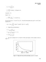
c. An example of speed droop characteristics is
shown in figure 3-11. The characteristics are for a
mechanical governor but the same principles can be
used for other engine/governor applications. The
chart is based on a six percent speed droop governor
on an engine running at rated speed at no load.
When full load is applied, engine speed drops to 94
percent (94%) of rated value (line B). The engine
can be brought to rated speed at full load by reset-
ting the governor (line A). However, with the load
removed, engine speed would increase beyond its
rated limit. Intermediate speed settings are shown
by lines C and D. Line E shows speed droop at 50
percent (50%) load.
d. Speed droop can be determined quickly by
loading the generator to full-load, observing the
speed, unloading the generator, and again observing
106
96
92
0 20 40 60 80
IOC
PER CENT, LOAD
SPEED VS LOAD-MECHANICAL GOVERNOR
A
6% DROOP-RATED SPEED AT
00%
LOAD
8 6% DROOP- RATED SPEED AT 0% LOAD
C
80
6
%
DROOP
-
INTERMEDIATE SETTINGS
E
4% DROOP-RATED SPEED AT 50% LOAD
Figure 3-11. Chart of speed droop characteristics.
the speed. Speed droop is usually adjusted by
lengthening or shortening the governor operating
levers, changing the ratio between governor move-
ment and throttle or gate movement.
e. Alternating Current (AC) Generators. Gover-
nors of prime movers driving AC generators which
operate in parallel with other generators must have
enough speed regulation or speed droop to prevent
surging of the load from one generator to another.
Ordinarily, three to five percent speed regulation is
adequate. Some governors have antisurging devices
to damp out the surges. Speed regulation should be
increased if the surges continue. Speed regulation of
governors controlling AC generators affects the fre-
quency and the load division between generators
but has almost no effect upon voltage.
f. Direct C
urrent (DC) Generators. Regulation of
DC generators affects voltage regulation and the
division of load between generators. In general, the
3-17
TM
5-685/NAVFAC
MO-912
speed regulation of generators operated in parallel
should be the same for each machine.
Speed
regula-
tion for generators operating individually should be
as favorable as possible without causing generator
surge resulting from sudden load changes. Ordi-
narily, 2.5 percent speed regulation is satisfactory
Voltage regulation of DC generators may be accom-
plished through adjustment of the speed droop of
the governor.
g. Types of governors. Usually four types of gov-
ernors are used; mechanical, hydraulic, pneumatic,
and electronic. When speed regulation must be
more precise, such as Defense Communications
Agency sites where no more than 0.8 percent varia-
tion is permitted, an electronic (isochronous) gover-
nor is used.
(1) The mechanical governor used in small
air-
cooled engines may be part of the fly-wheel. The
governor in multicylinder engines is usually a sepa-
rate assembly driven by gear or belt from a cam-
shaft or crankshaft. A typical mechanical governor,
shown in figure 3-12, operates as follows: the gov-
ernor drive gear (2) drives the governor shaft (10)
and the governor weights (4). Centrifugal force
moves the weights away from the shaft which push
the operating-fork riser (6) against the operating
fork
(ll),
rotating the operating-fork shaft (7) and
moving the governor arm (9). In the external view,
the governor spring (A) is connected to the governor
arm and opposes movement of the governor weights
away from the shaft. Adjusting screw (c) adjusts the
tension of the governor spring, establishing the
speed at which the prime mover operates. The
greater the governor-spring tension, the lower the
governed speed. The auxiliary adjusting screw (D)
adjusts the droop of the governor. Turning this
screw in closer to the arm decreases the droop of the
governor; this screw should be turned in as far as
possible without allowing the engine to surge. Aux-
iliary adjusting screw (B) is turned in to damp out
surging of the engine at light-load or no-load; it
should not be turned in so far that it increases the
speed of the generator at no-load.
(2)
The hydraulic governor (see fig 3-13) is
used on large prime movers as well as diesel en-
gines as small as 100 hp. The governor usually
includes: a speed-responsive device, usually fly-
weights; a valve mechanism; a regulating cylinder
and piston; and a pressure pump and relief valve.
The assembly is adjustable for various ranges of
speed and sensitivity. The hydraulic principle pro-
vides greater power than could be obtained from a
mechanical type. Since the flyweights only control
an easily moved pilot valve (which in turn controls
the hydraulic action), the governor can be made to
operate accurately and smoothly. Remote control
3-18
and automatic equipment can be applied to the hy-
draulic governor.
(a)
The hydraulic governor requires pressur-
ized oil for operation. This oil can come from the
engine or from a separate sump in the governor. Oil
is admitted to an auxiliary oil pump in the governor.
The auxiliary pump furnishes necessary pressure to
actuate the governor mechanism. In the governor
shown, the fuel to the engine is decreased by the
action of the fuel-rod spring
(10)
on the fuel rod
(
12)
and increased by the opposing action of the hydrau-
lic serve piston
(14),
the admission of oil to which is
controlled by a pilot valve (4). The pilot valve is
controlled by flyweights of the governor (5) which
are driven by the governor shaft through gearing to
the engine. The centrifugal force of the flyweights in
rotation is opposed by the speeder spring
(6),
the
compression of which determines the speed at
which the governor will control the engine. The
speeder-spring compression is adjusted through the
rotation of the speed-adjusting shaft (8) which
raises or depresses the spring fork (7) through its
linkage lever.
(b) The dro
op
of the speed-load characteristic
is adjusted by changing the effective length of the
floating lever (11). This is accomplished by moving
the droop-adjusting bracket forward or backward in
the slot of the floating lever. The effective length of
the lever should be shortened to decrease the speed
droop and lengthened to increase the speed droop.
(3) The pneumatic governor (air-vane type) is
used in certain small generator plants (see fig
3-14). The engine flywheel includes an integral fan
which forces air outward from the drive shaft. The
amount of air flowing from the engine depends on
engine speed. A movable air vane is placed in the air
stream. The air vane (blade) acts as a governor
since the air pressure depends upon engine speed.
The air pressure on the vane is opposed by a gover-
nor spring and these forces operate through linkage
to control the throttle of the engine.
(4) Electronic (isochronous) speed control is the
maintenance of constant engine speed independent
of the load being carried (zero droop). An isochron-
ous governor will maintain, or can be adjusted to
maintain, constant engine speed (within 0.2 percent
variation). This type of governor can be a combina-
tion of a conventional hydraulic governor and an
electronic load-sensing system, or an all-electric
system.
(a) Speed control by the hydraulic governor,
see paragraph
3-8d(2),
depends on variation in cen-
trifugal force created by flyweights (centrifugal
forces are not used in electric types). This force
operates a piston-type pilot valve which controls the
0
1
BEARING
-EXTERNAL
TM
5-685/NAVFAC
MO-912
0
11
\
OPERATING FORK
0
12
BUMPER SPRING
-
n
(13)
BUMPER SPRING SCREW
L
\
w
VIEW
ADJUSTING
ADJUSTABLE
I
SCREW
I
SCREW
GOVERNOR
SPRING
DRIVE
GEAR
COCK NUT
0
14
BUMPER SPRING SCREW
Figure 3-12. Mechanical Governor.
3-19
TM
5=685/NAVFAC
MO-912
FROM ENGINE
Figure 3-13. Hydraulic Governor.
1)
PLUNGER, 2) GEAR PUMP DRIVE,
3)
GEAR PUMP
IDLER, 4) PLUNGER PILOT VALVE, 5) FLYWEIGHT,
6) SPEEDER SPRING, 7) SPRING FORK,
8) SPEED-ADJUSTING SHAFT, 9)
SPEED-ADJUSTING
LEVER, 10) SPRING,
11)
FLOATING LEVER,
12) FUEL ROD, 13) TERMINAL LEVER,
14) SERVO PISTON
THROTTLE ADJUSTING SCREW
GOVERNOR
BLADE
NEEDLE VALV
ADJUSTING
Figure 3-14. Carburetor and pneumatic governor.
flow of high-pressure oil to a servomotor, thereby
operating fuel controls.
(b) The isochronous system uses electronic
sensing and amplifying devices that actuate a type
of servomotor throttle control. The system is used
with power generation where precise frequency con-
trol is required. An isochronous system may be sen-
sitive to frequency changes (engine speed) or to both
frequency and load. When responsive to load
changes, the system corrects fuel settings before
load changes can appreciably modify engine speed
or frequency.
3-9. Air intake system.
Approximately 15 pounds of air is required to burn
one pound of fuel. Accordingly, the air requirement
for a 2000 horsepower engine is about 3600 cubic
feet per minute. The same horsepower-to-air rela-
tionship applies to engines for other power ratings.
Intake air carries dust particles, water vapor and
other foreign material. Since these materials can
damage moving parts within the engine, filtration
of the intake air is necessary. A 2000 horsepower
engine, breathing air containing three parts per
million dust contamination, would take in 25
pounds of foreign material in 1000 operating hours.
An air intake system must collect, filter, and dis-
tribute the required air to the engine cylinders. This
must be accomplished with a minimum expenditure
of energy (pressure drop). The objective of air filtra-
tion is the reduction of engine component wear. Sev-
eral types of air filters or air cleaners are used. The
pleated-paper type are strainers, porous enough to
pass air but able to remove solid particles larger
than 0.002 of an inch. Larger engines use an
oil-
bath air cleaner (see fig 3-15). In oil-bath cleaners
air is drawn through an oil bath. Solid particles are
trapped and settle in the unit’s bottom pan.
a. Supercharging. Supercharging increases the
amount of air taken into a working cylinder. This
provides the injected fuel oil with more oxygen to
enable combustion of a larger charge of air/fuel mix-
ture. Power output of a certain size engine is
thereby increased, enabling use of smaller engines
where space prohibits larger engines.
(1)
Advantages. The power output of a natu-
rally aspirated engine is limited by the normal pres-
sure and oxygen content of the atmosphere. When
supercharging is used, the intake valve (port) closes
with the cylinder under the initial pressure. Super-
charging is particularly effective at higher alti-
tudes. The supercharged engine can develop greater
horsepower than the standard naturally-aspirated
unit. The fuel consumption of a supercharged unit
will not exceed that of comparable horsepower sizes
of naturally-aspirated units.
3-20
TM
5-685/NAVFAC
MO-912
Figure 3-15. Oil bath air cleaner:
(2)
Methods. The most successful method of su-
percharging is the use of a turbocharger driven by
exhaust gas (see fig 3-16). The heat and energy
pulsations in the exhaust gas, which are usually
lost in the exhaust silencer, are used to drive a
single-stage centrifugal turbine. The exhaust gas
turbine is coupled to a centrifugal compressor that
compresses the air to a pressure of four or five
psi. The engine’s pressurized air is then delivered to
the individual cylinders through the intake mani-
fold.
(3) Disadvantages. Although the supercharged
engine has many advantages over nonsupercharged
engines, its disadvantages are not insignificant. The
turbocharger is another piece of equipment to main-
tain and operate. It operates at varying speeds de-
pending on engine load, barometric pressure, inlet
air temperature, exhaust temperature, smoke con-
tent of the exhaust, or accumulations of dust and
dirt on the impeller and diffuser. It may operate at
very high speed (up to 120,000 rpm) with a full load
on the engine and thus be subjected to all the
troubles of high-speed equipment. With proper
maintenance, however, the turbocharger can be op-
erated very successfully. If the turbocharger fails,
the engine can usually be operated at reduced load
as a nonsupercharged engine. The turbocharger can
be partially dissembled and the opening blocked off,
but the coolant should be allowed to circulate
through the supercharger.
(4)
Operating instructions. Manufacturer’s in-
structions must be followed to ensure proper opera-
tion of superchargers. Filtered air only should enter
the air inlet, because foreign matter can cause rotor
imbalance and damaging vibration. The manufac-
turer’s recommendations for lubrication must be fol-
lowed. Proper lubrication is necessary because the
unit operates at high speed and at high tempera-
ture. Not more than 15 seconds should elapse be-
tween the start of rotation and an oil pressure indi-
cation of 12 to 71 psi. Coolant circulation through
the turbocharger should be regulated so the tem-
perature rise does not exceed 30” Fahrenheit at full
engine load. A rise in excess of 30” Fahrenheit indi-
cates faulty circulation. Coolant should be allowed
to circulate through the turbocharger for about 5
minutes after the engine is shutdown.
b. Aspiration. The term “naturally-aspirated” is
applied to engines that are not supercharged. A four
stroke cycle engine performs its own air pumping
action with the piston intake stroke. When it is
supercharged, a four-stroke engine with a blower or
turbocharger provides pressure in the intake mani-
fold greater than atmospheric. The increased pres-
sure in the intake manifold is referred to as “boost”.
Two stroke cycle engines require an air supply un-
der pressure to provide scavenging air.
3-1
0. Exhaust system.
Components. The exhaust system consists of the
engine exhaust manifold and includes piping, ex-
pansion joints, silencers, and exhaust pipe. Also the
system may include exhaust waste heat recovery
equipment. The purpose of the system is to remove
exhaust gas from engine cylinders to the atmo-
sphere. Parts of the system are shown in figure 3-6.
(a) Leak-free. Exhaust systems must be leak free
to protect personnel from asphyxiation, and equip-
ment from fire and explosion. Exhaust from gaso-
line engines can contain dangerous carbon monox-
ide. Diesel engine exhaust includes objectionable
smoke and odors. On supercharged engines, leaks
ahead of the turbine cause a loss of power.
(b)
Piping. Exhaust piping must be the correct
size to minimize exhaust back pressure. Connec-
tions between exhaust manifold and piping should
have an expansion joint and the exhaust pipes
should slope away from the engine. Also the exhaust
pipes should have suitable devices to prevent entry
of rainwater. The length of tail pipes from silencer
to atmosphere should be kept to a minimum.
(c)
Silencers.
Silencers are used to reduce or
muffle engine exhaust noise. Silencing engine ex-
haust sounds consists of trapping and breaking up
3-21
TURB’
IMPELLER
GAS INLET
ENGINE
CYLINDER
EXHAUST GAS
DISCHARGE
ENGINE EXHAUST GAS FLOW
AMBIENT AIR
!=)
COMPRESSED AIR FLOW
JNLET
Figure 3-16. Diagram of turbocharger operation.
the pressure waves. Usually, a cylindrical unit with
baffles, expansion chambers, and sound absorption
materials is used.
3-1
1.
Service practices.
a. Maintenance program. Service practices for
diesel engines consist of a complete maintenance
program that is built around records and observa-
tions. The maintenance program includes appropri-
ate analysis of these records. DD Form 2744
(Emergency/Auxiliary Generator Operation Log)
should be used to record inspection testing of
emergency/auxiliary generators. A copy of DD Form
3-22
2744 is provided at the back of this publication. A
completed example of DD Form 2744 is located in
appendix
F,
figure F-l. It is authorized for electronic
generation.
(1) Record keeping. Engine log sheets are an
important part of record keeping. The sheets must
be developed to suit individual applications (i.e.,
auxiliary use) and related instrumentation. Accu-
rate records are essential to good operations. Notes
should be made of all events that are or appear to be
outside of normal range. Detailed reports should be
logged. Worn or failed parts should be tagged and
protectively stored for possible future reference and
_-
analysis of failure. This is especially important
when specific failures become repetitive over a pe-
riod of time which may be years.
(2) Log sheet data. Log sheets should include
engine starts and stops, fuel and lubrication oil con-
sumption, and a cumulative record of the following:
(a) Hours since last oil change.
(b) Hours since last overhaul.
(c) Total hours on engine.
(d)
Selected
t
emperatures and pressures.
b.
Troubleshooting. Perform troubleshooting pro-
cedures when abnormal operation of the equipment
is observed. Maintenance personnel should then re-
fer to log sheets for interpretation and comparison
of performance data. Comparisons of operation
should be made under similar conditions of load and
ambient temperature.
The general scheme for
troubleshooting is outlined in the following para-
graphs.
(1) Industrial practices. Use recognized indus-
trial practices as the general guide for engine ser-
vicing. Service information is provided in the manu-
facturer’s literature and appendixes B through G.
(2) Reference Literature. The engine user must
refer to manufacturer’s literature for specific infor-
mation on individual units. For example, refer to
table 3-5 for troubleshooting an engine that has
developed a problem.
Table 3-5. Diesel engines troubleshooting.
HARD STARTING OR FAILS TO START
Cause Remedy
Air intake restricted. Check intake and correct as required.
Fuel shut-off closed, Make sure shut-off is open and supply is at
low supply of fuel. proper level.
Poor quality fuel. Replenish fuel supply with fresh, proper quality
fuel.
Clogged injector. Clean all injectors, refer to appendix G.
Injector inlet or drain Check all connections and correct as required.
connection loose.
En-
Schedule the overhaul and correct as required.
gine
due for overhaul.
Incorrect timing. Perform timing procedure, refer to appendix G.
ENGINE MISSES DURING OPERATION
Air leaks in fuel
suc-
Check fuel suction lines and correct as
re-
tion lines. quired.
Restricted fuel lines. Check fuel lines and correct as required.
Leakage at engine
Refer to manufacturer’s instructions and correct
valves. as required.
Incorrect timing. Perform timing procedure, refer to Appendix G.
EXCESSIVE SMOKING AT IDLE
Restricted fuel lines. Check fuel lines and correct as required.
TM
5-685/NAVFAC
MO-912
Table 3-5. Diesel engines troubleshooting-Continued
EXCESSIVE SMOKING AT IDLE
Cause
Remedy
Clogged injector.
Clean all injectors, refer to appendix G. Refer
Leaking head gasket to manufacturer’s instruction and correct as
or
blowby.
Engine due required. Schedule the
overhaul
and correct as
for overhaul. Incorrect required. Perform timing procedures. refer to
timing. appendix G.
EXCESSIVE SMOKING UNDER LOAD
The same causes for
“idle” apply.
Air intake restricted.
High exhaust back
pressure.
Poor quality fuel.
The same remedies for “idle” apply.
Check air intake and correct as required.
Check exhaust system and turbocharger; correct
as required.
Replenish fuel supply with fresh, proper quality
fuel.
Engine overloaded. Reduce load to proper ievel.
LOW POWER OR LOSS OF POWER
Air intake restricted.
Poor quality fuel.
Check air intake and correct as required.
Replenish fuel supply with fresh, proper quality
fuel.
Clogged injector. Clean
all
injectors, refer to appendix G.
Faulty throttle linkage Check linkage and governor refer to
manufac-
or governor setting too
turer’s instructions and correct as required.
low.
Clogged filters and
screens.
Clean filters and screens.
Engine overloaded.
Engine due for over-
haul.
Reduce load to proper level.
Schedule the overhaul and correct as required.
Incorrect timing.
En-
Perform timing procedure, refer to appendix G.
gine requires tune-up. Perform tune-up procedure, refer to appendix
G.
DOES NOT REACH GOVERNED SPEED
The same causes for
“low power”, apply.
The same remedies for “low power”, apply.
EXCESSIVE FUEL CONSUMPTION
Air intake restricted.
High exhaust back
pressure.
Poor quality fuel.
Faulty injector.
Engine overloaded.
Engine
due for over-
haul.
Incorrect timing.
Air intake restricted.
Check air intake and correct as required.
Check exhaust system and turbocharger; correct
as required.
Replenish fuel supply with fresh. proper quality
fuel.
Clean all injectors, refer to appendix G.
Reduce load to proper level.
Schedule the overhaul and correct as required.
Perform timing procedure, refer to appendix G.
ENGINE QUITS
Check air intake and correct as required.
3-23
TM
5-685/NAVFAC
MO-912
Table 3-5. Diesel engines troubleshooting Continued
ENGINE QUITS
Cause
Remedy
High exhaust back Check exhaust system and correct as required.
pressure turbocharger.
Fuel shut-off closed,
Make sure shut-off is open and supply is at
low supply of fuel.
proper level.
Poor quality fuel.
Replenish fuel supply with fresh, proper quality
fuel.
Faulty injector. Clean all injectors, refer to appendix G.
ENGINE SURGES AT GOVERNED SPEED
Air leaks in fuel
suc-
Check fuel suction lines and correct as
re-
tion lines.
quired.
Faulty injector. Clean all injectors, refer to appendix G.
Leaks in oil system. Check for oil leaks, check oil lines, check
crankcase drain plug and gasket; correct as re-
quired.
Engine due for
over-
Schedule the overhaul and correct as required.
haul.
Piston rings or cylinder liners may be worn.
SLUDGE IN CRANKCASE
Fouled lubricating oil
strainer or filter.
Check strainers and filters, remove and service
as required, reinstall on engine with new gas-
kets.
Faulty thermostat.
Check coolant thermostats, engine may be too
cool.
Dirty lubricating oil.
Drain old oil, service strainers and filters, refill
with fresh oil.
LUBRICATING OIL DILUTED
Fuel in lubricating oil. Check for loose injector inlet or drain connec-
tion; correct as required. Drain old oil, service
strainers and filters, refill with fresh oil.
Coolant in lubricating Check for internal coolant leaks. Correct as
oil.
required. Drain old oil, service strainers and
filters, refill with fresh oil.
LOW LUBRICATING OIL PRESSURE
Faulty oil line, suction Check oil lines for good condition, fill to
line restricted, low oil proper oil level with fresh oil.
level.
Engine due for
over-
Schedule the overhaul and correct as required.
haul.
Piston rings, crankshaft bearings, or cylinder
liners may be worn.
ENGINE RUNNING TOO HOT
High exhaust back
Check exhaust system and turbocharger; correct
pressure. as required.
Faulty thermostat. Check coolant thermostats; correct as required.
Low lubricating oil Fill to proper level with fresh oil.
level.
Engine overload.
Reduce load to proper level.
Faulty cooling system Check components; correct as required. Fill
component (pump,
cooling system to proper level with coolant.
hose, radiator fan belt).
3-24
Table 3-5. Diesel engines troubleshooting-Continued
ENGINE RUNNING TOO HOT
Cause
Remedy
Low coolant level. Air Refer to appendix D.
in system.
ENGINE KNOCKS
Poor quality fuel.
Replenish fuel supply with fresh, proper quality
fuel.
Air leaks in fuel
suc-
tion lines.
Engine overloaded.
Engine running too
hot.
Check fuel suction lines and correct as
re-
quired.
Reduce load to proper level.
Repeat the procedures for “too hot”, above.
Faulty vibration
damper or flywheel.
Engine due for
over-
haul.
Correct as required, refer to manufacturer’s
instructions.
Schedule the overhaul and correct as required.
3-12. Operational trends and engine over-
haul.
a.
Trending
data. Usually, a graphic presentation
of data simplifies detection of a trend toward dete-
riorating engine performance. Samples of graphic
aids are shown in figures 3-17 and
3-18.
These
include plots of fuel and lubricating oil consumption
versus electric load (power production), monthly
pressure checks (engine parameters), and mainte-
nance
data showing cylinder wear and crankshaft
deflection. Interpretation of data and details are
provided in the specific engine manufacturer’s lit-
erature. These kinds of data aid in developing crite-
ria for equipment performance and determining the
need for engine overhaul or other repair.
(1) Samples of information appearing in figure
3-17 are as follows:
__
(a)
“A”
on the chart may indicate lack of op-
erating hours.
(b)
“B”
on the chart may indicate a peak
value or seasonal characteristic.
(c) “C” on the chart may indicate the result of
frequent starts or stops.
“D” on the chart indicates a
steady improvement.
(d) “E” on the chart shows lubricating oil
consumption. The steady decline at “F” may indi-
cate a developing engine problem (i.e., oil control
ring failure, lube oil leakage into combustion areas,
or excessive oil feed).
(2) Samples of information appearing in part A
of figure 3-18 are as follows:
(a) “A” on the chart may indicate faulty fuel
injectors, or deviations in fuel timing.
(b)
“B”
on the chart (sharp rise in compres-
sion) can be caused by carbon build up or may
indi-
cate
new piston rings were installed.