POWER PLANT ACOUSTICS Episode 9 potx
Bạn đang xem bản rút gọn của tài liệu. Xem và tải ngay bản đầy đủ của tài liệu tại đây (366.32 KB, 9 trang )
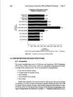
Item 13 shows an indoor noise excess of 3 to 6 dB in
the 125- to 1000-HZ octave bands. This would be
rated as “marginal”. If the NC–25 criterion is a
justified choice, these noise excesses should not be
permitted. A number of other factors could influ-
ence the decision. If the housing is exposed to
other uncontrollable excess noise (such as nearby
highway activity or base aircraft activity), power
plant noise might not appear so noticeable. How-
ever, if the base is located in a very quiet suburban
or rural area, with very little other noise, the pow-
er plant noise will be very noticeable. If the base is
located in a very hot or very cold region, year-
round, and the windows are kept closed most of the
time, and if inside sources, such as air conditioners
or central heating and cooling systems, are in near-
ly continuous use, external noise sources will not
be as noisy when heard indoors. These various con-
ditions could be used to support or justify adjust-
ments to the NC criterion. In the present problem,
it is assumed that such factors have already been
considered, and the NC–25 selection is a valid
choice.
(c) A CNR analysis should be carried out as
a means of checking or confirming the expected re-
action of the housed personnel to the power plant
noise. The N&V manual (para. 3–3c) summarizes
the procedure.
Figure 4–24 shows the CNR grid
upon which the outdoor power plant SPLs are
plotted (taken from Item 8 of fig. 4–23). A noise
level rank of “e” is obtained.
4-35
of determining the correction number for the back-
ground noise in the area. If background noise
measurements can be made at the existing base,
N&V figure 3–4 should be used; otherwise the
background noise correction may be estimated by
selecting the most nearly applicable conditions of
N&V table 3–4. For this sample problem, a back-
ground noise correction of +1 is used. N&V table
3–5 is then used to determine other correction
numbers applicable to the problem. The following
corrections are here assumed:
Correction for temporal or seasonal factors
Day and night
o
Summer and winter
o
“On” full time
o
Correction for character of noise
No unusual sounds
o
Correction for previous exposure
Some previous exposure and good
community relations
o
Background noise correction
From discussion above
+1
Total corrections
+1
The CNR (composite noise rating) is then e + 1 =
F. The N&V figure 3–5 is used to estimate the ex-
pected community response, where base personnel
are assumed to be the equivalent of “average resi-
dents. ” A CNR value of F indicates a strong reac-
tion against the noise for the conditions assumed
here. A noise reduction of about 10 dB would bring
the reaction down to “sporadic complaints, ” which
might be considered a reasonable condition. CNR
values of C or D are often encountered in nonmili-
tary situations.
(d) On the basis of both indoor and outdoor
power plant noise at the base housing, the above
analyses strongly suggest the need for a 5- to
10-dB reduction of noise, with principal emphasis
on noise control in the 125- to 1000-HZ frequency
range.
(e) Several possibilities exist for reduction
of the excess noise. If the base has a large land
area and is not yet constructed, the power plant
and the housing area can be moved farther apart.
An increase in distance from 1200 ft. to 2000 ft.
would give a 250-Hz noise reduction of 5 dB, and an
increase in distance to 3000 ft. would give a 250-Hz
noise reduction of 10 dB (from N&V table 6–4). As
one alternative, the base housing can be designed
and constructed to have higher TL walls and closed
windows facing the power plant. This would reduce
indoor SPLs but would not change the outdoor
SPLs. If possible, other large buildings on the base
could be used to shield the housing area from the
power plant. Two feasible alternatives could be ap-
plied at the power plant. In one, special large-
volume, low-pressure-drop mufflers could be used,
either singly or in series, in the exhaust lines from
the engines to provide greater insertion loss than is
quoted in table 3–2 for the rather conventional
grades of mufflers. Such mufflers have been used
successfully with large engines located as close as
600 to 800 ft. from residential areas. As another al-
ternative, an outdoor L-shaped barrier wall ex-
tending above the top of the exhaust pipe openings
for the engines in Engine Room No. 1 could be
built above the second-floor Mechanical Equipment
Room and the south wall of the Engine Room to
give a beneficial amount of noise reduction for the
exhaust of the three 3500-hp engines. The exhaust
mufflers for the two 1600-hp engines could be
specified and purchased to have a larger amount of
insertion loss than assumed in the figure 4–4 analy-
sis. The 900-hp engine is the quietest one of the en-
tire group and may or may not need additional
muffling, depending on the success of the other
pursuits.
(10) Other engine noise to on-base housing.
(a) Turbocharger inlet noise for the three
outdoor inlets of the 3500-hp engines should be
checked for meeting the desired indoor and outdoor
levels of the base housing. The PWLs of the un-
muffled inlet of one such engine is given in Item 16
of figure 4–2. These levels should be increased by 5
dB (for three engines), then extrapolated to the
1200-ft. distance. The inlet openings are partially
shielded by the power plant building, and the bar-
rier effect of the building can be estimated. Ab-
sorbent duct lining in the air inlet ducts or dissipa-
tive mufflers at the intake to the air cleaners can
be very effective at reducing the high-frequency
tonal sounds of the turbochargers.
(b) Sound from Engine Room No. 2 can es-
cape from the open vent on the east wall of this
room and travel directly to the housing area. Fig-
ure 4–23 shows the principal steps in the analysis
of this part of the problem.
4-37
mately those shown in figure 4–12. The PWL of the
noise escaping through the unmuffled vent is calcu-
lated from equation 7–18 of the N&V manual. This
is given in Item 2 of figure 4–25, for the open vent
area of 40 ft.
2
. A 3-ft long low-pressure-drop dissi-
pative muffler (data from table 3–10) is first
planned for the vent opening (Item 6 in fig. 4-25).
The noise radiating from the open front of the muf-
fler has a small amount of directivity increase to-
ward the housing. If the opening could freely radi-
ate its sound in all horizontal directions, there
would be no special directional effect, and normal
sound propagation would exist. However, the
presence of the large-area east wall of the building
acts as a baffle that keeps one-half of the sound
from radiating to the west. Thus, the sound that
would have gone to the west (if the building were
doubles the PWL of the sound radiating to the east
and a 3-dB increase is added at Item 7. Combining
all the factors, Item 13 of the analysis shows that
the vent will produce 2-dB excess indoor levels at
the housing in the 500-Hz band. When added to all
other noise coming from the power plant, the total
excess could be even larger. Thus, a better design
would be either a 5-ft long low-pressure-drop muf-
fler or a 3-ft long high-pressure-drop muffler or
some other acceptable combination available from a
muffler supplier.
(c) Next, noise radiated from the exterior
east wall of the building should be checked. Materi-
al from paragraph 3–2a and equation 3–3 are in-
volved (L
W
= L
P
– TL + 10 log A–16). Figure 4-26
summarizes the calculations of the PWL of the
noise radiated externally by the east wall of En-
not there), instead is reflected to the east. This
gine Room No. 2.
Column 2 gives the SPL inside the Engine Room,
graph 3–2a, it should be determined that this cal-
as taken from figure 4–12. Column 3 gives the TL
of the exterior wall of the building, 10-in. -thick
hollow-core concrete block, from N&V table 5-9.
Column 4 represents the term (10 log A–16), where
the area of the east wall is 30
x 40 = 1200 ft.
2
when the 40-ft.
2
area of the muffled vent opening is
neglected). Column 5 is then the radiated PWL of
equation 3–3 (Column 5 = Column 2 – Column 3 +
Column 4). In accordance with the caution of para-
culated radiated PWL does not exceed the low-
frequency PWL of the sources inside the room.
This is done by comparing the Column 5 values
with the sum of the engine casing PWLs of the
three engines in Engine Room No. 2 (from fig. 4–3
and 4–4). This sum is shown in Column 6. It is clear
that the Column 5 values are less than the Column
6 values. The Column 5 PWL is next extrapolated
to the base housing with the use of figure 4–27.
4-39
that the noise radiated by the wall will fall about 20
to 30 dB below the NC–25 indoor criterion levels.
Thus, wall-radiated noise will be of no concern in
this sample problem.
(d) Engine noise escaping through the room
should be checked in accordance with paragraph
3–2d. The roof deck for the building is of 2-in. -
thick poured concrete on corrugated metal. The TL
of the roof deck is estimated to be about the same
as that of 2-in. -thick dense plaster (N&V table
5–11) or about 4 dB less than that of 4-in. -thick
dense plaster (N&V table 5–ll) or about 5dB less
than that of 4-in thick dense concrete (N&V table
5–8), whichever is less. Equation 3–3 is used here
to obtain the PWL radiated separately by each En-
gine Room roof. Then, the directivity loss in the
horizontal direction is applied, using table 3-1. The
power plant building has a parapet, so it qualifies
as a Type 1 roof, and the smaller D dimension of
each Engine Room is 40 ft., so the column of
directivity corrections for “D under 50 ft. ” should
be used. Each Engine Room has different sound
sources, so the effect of each roof section must be
calculated. Only one roof (for Engine Room No. 2)
is illustrated in figure 4–28.
4-41
noise obtained with the use of equation 3–3, using
the TL of 2-in. dense plaster and an area of 40
x 50
= 2000 ft.
2
Comparison of Items 10 and 12 shows
that roof-radiated noise is also about 20 to 30 dB
below NC–25 indoor sound levels at the base
housing.
(e) This completes the basic analysis of the
community noise obtained from each noise source
of group of noise sources considered in this sample
calculation. One final check is required of the en-
tire plant. When the analysis is completed on each
individual source radiating toward the housing, and
suitable noise control measures are tentatively se-
lected for each source, a final analysis should be
made of the entire plant. All sources together must
not exceed the noise criterion in all octave bands.
If a few sources combine to produce excessive
noise in one or more octave bands, the noise con-
trol treatments for those sources in those octave
bands should be improved sufficiently to eliminate
the calculated noise excess completely. This final
step in the total analysis should assure a satisfacto-
ry noise design for the complete installation.
4-3. Example of an on-grade packaged gas
turbine generator plant.
The gas turbine generator plant plays an increas-
ingly prominent role in out-of-the-way locations for
both continuous and peak-load applications. Its rel-
ative portability means that it can be moved in and
set up almost anywhere power is needed, but, by
the same token, its light weight makes it a poten-
tial noise problem. The gas turbine is basically a
very noisy device, and the simple cabinet-like en-
closure and the all-too-frequent shortage of ade-
quate mufflers do not always control the noise.
a. Description of power plant. In this example, a
15-MW plant is supplied by the manufacturer in a
packaged form as shown in figure 4–29.