gdi programming with c sharp phần 2 ppt
Bạn đang xem bản rút gọn của tài liệu. Xem và tải ngay bản đầy đủ của tài liệu tại đây (4.46 MB, 70 trang )
Go to the Solution Explorer window and expand the References node. The System.Drawing namespace is listed there Figure
2.7).
Figure 2.7. The System.Drawing namespace in a project
Note
Visual Studio .NET version 1.0 (or later) automatically adds a reference to the System.Drawing.dll library. In that case,
you may not need to add a reference to the library.
5.
After adding a reference to System.Drawing.dll, you must import System.Drawing and other related namespaces, depending on the
classes your application will use. For now, we will import the System.Drawing and System.Drawing.Drawing2D namespaces. We
add the following two lines to the top of our class:
using System.Drawing;
using System.Drawing.Drawing2D;
6.
You can also qualify a namespace reference by directly adding it as a prefix of the class. For example, if you don't want to use the using
statements defined here, you can define a class as follows:
System.Drawing.Graphics g = e.Graphics;
This document was created by an unregistered ChmMagic, please go to to register it. Thanks.
Note
If you create a Windows application using VS.NET, only the line using System.Drawing.Drawing2D needs to be written
because using System.Drawing will already be there.
2.3.3 Getting a Graphics Object in an Application
After adding a GDI+ library reference to the project, the next step is to decide on a drawing surface. In a Windows application, a form is a
drawing surface. Every form has a Graphics object associated with it, which provides the drawing functionality.
In the .NET Framework, the Graphics class represents a GDI+ Graphics object, which defines methods and properties to draw and fill graphics
objects. Whenever an application needs to draw anything, it must go through the Graphics object.
Caution
There is no way to create a Graphics object using the new operator. For example, if you write the following code, you will get
a compiler error:
Graphics g = new Graphics ()
There are several ways to obtain a Graphics object associated with a form. Three of them are described in the following sections.
2.3.3.1 Using the Paint Event of a Form
You can get a Graphics object corresponding to a form using the PaintEventArgs property of the form's paint event. For example, the following
code gets a Graphics object from PaintEventArgs:
private void form1_Paint(object sender, PaintEventArgs e)
{
Graphics g = e.Graphics;
}
You can add the form's paint event handler using the Properties window. As Figure 2.8 shows, we add Form1_Paint (the default name) as the
paint event handler.
This document was created by an unregistered ChmMagic, please go to to register it. Thanks.
Figure 2.8. Adding the Form_Paint event handler
Tip
Double-clicking in the paint event drop-down menu in the Properties window also adds the event handler.
2.3.3.2 Overriding the OnPaint Method
Another way to get a Graphics object associated with a form is to override the OnPaint method of the form, which uses PaintEventArgs in a
manner similar to the Form1_Paint event. The following code snippet overrides the OnPaint method of a form:
protected override void OnPaint(PaintEventArgs e)
{
Graphics g = e.Graphics;
}
This document was created by an unregistered ChmMagic, please go to to register it. Thanks.
2.3.3.3 Using Other Methods
Sometimes you don't want to use the OnPaint method. For example, you might want to draw something on a button or a menu click event
handler. The Form class provides the CreateGraphics method, which returns a Graphics object. The following code snippet creates a Graphics
object using the CreateGraphics method and calls a method of the Graphics class:
Graphics g = this.CreateGraphics();
g.Clear(this.BackColor);
g.Dispose();
As this snippet shows, we call the Clear method of the Graphics class, which sets the background color of the surface as the background color
of the form.
Caution
When you create a Graphics object using the CreateGraphics method, you must dispose of that object explicitly by calling the
Dispose method to release the resources associated with it.
You can also use the FromImage, FromHwnd, and FromHdc static methods of the Graphics class to create Graphics objects from images,
window handles, and window handles to device contexts, respectively. We will discuss these methods in more detail in Chapter 3 (Section
3.2.3.3 ).
The following code creates a Bitmap object and calls the static FromImage method, using a Bitmap object as an input parameter, which returns
a Graphics object.
Bitmap bmp =
new Bitmap(600,400,PixelFormat.Format32bppArgb);
Graphics g = Graphics.FromImage(bmp);
The following code creates a Graphics object from a window handle. In this example, this refers to a Windows Form. You can even pass
Form1.Handle if your form is Form1.
Graphics g = Graphics.FromHwnd(this.Handle);
2.3.4 Creating Pens and Brushes
This document was created by an unregistered ChmMagic, please go to to register it. Thanks.
Once you have a Graphics object, the next step is to decide what you're going to draw on the surface. You may need one or more of the three
objects: pen, brush, or image. In this chapter we will concentrate on pens and brushes only. Images are discussed in Chapters 7 and 8.
In GDI+ the Pen and Brush classes represent a pen and a brush, respectively. The abstract Brush class functionality is accessed through its
derived classes: SolidBrush and HatchBrush, among others. Pens are used when you need to draw lines, rectangles, and curve boundaries.
Brushes are used when you need to fill graphics objects. Chapter 4 discusses pens and brushes in detail.
The Pen class constructor takes as arguments the color and width of the pen. The following code creates a red pen with a width of 3 pixels and
a black pen with a width of 1 pixel. The Pens class provides static members, each of which represents a pen with a particular color.
Pen redPen = new Pen(Color.Red, 3);
Pen blackPen = Pens.Black;
The SolidBrush class represents a solid brush in GDI+. This class's constructor takes a color as an argument. The following code creates a
green solid brush.
SolidBrush greenBrush = new SolidBrush(Color.Green);
2.3.5 Drawing Graphics Shapes
Once you have the surface, pens, and/or brushes, you can draw lines, shapes, curves, or images. The Graphics class provides draw and fill
methods to draw and fill graphics shapes, curves, or images. For example, the FillRectangle method draws a rectangle with a filled color, and
DrawRectangle draws the boundary of a rectangle with the specified pen. Draw methods take a pen as an argument, and fill methods take a
brush.
We override the OnPaint method and write the code in Listing 2.1 on this method. As Listing 2.1 shows, we first set the smoothing mode of the
Graphics object by setting its SmoothingMode property. The SmoothingMode enumeration is defined in the System.Drawing.Advanced2D
namespace and is used to set the quality of a graphics object. In our code, we set the smoothing mode to anti-aliasing. We will discuss this in
more detail in Chapters 8 and 9.
After that we create a rectangle, two pens, and a solid brush. In the next code snippet, we call the DrawRectangle, FillEllipse, and DrawLine
methods. The DrawRectangle method draws the boundaries of a rectangle, the FillEllipse method fills an ellipse with the specified brush, and
the DrawLine method draws a line using the specified pen. Chapter 3 will discuss the fill and draw methods in more detail.
Listing 2.1 Drawing lines, rectangles, and ellipses
protected override void OnPaint(PaintEventArgs e)
{
// Obtain the Graphics object
Graphics g = e.Graphics;
// Set the smoothing mode of the surface
g.SmoothingMode = SmoothingMode.AntiAlias;
// Create a rectangle with height 100 and width 100
Rectangle rect = new Rectangle(20, 20, 100, 100);
// Create two Pen objects, one red and one black
Pen redPen = new Pen(Color.Red, 3);
Pen blackPen = Pens.Black;
This document was created by an unregistered ChmMagic, please go to to register it. Thanks.
// Create a SolidBrush object
SolidBrush greenBrush = new SolidBrush(Color.Green);
// Draw shapes and lines
g.DrawRectangle(redPen, rect);
g.FillEllipse(greenBrush, rect);
g.DrawLine(blackPen, 0, 250, this.Width, 250);
g.FillEllipse(Brushes.Blue, 70, 220, 30, 30);
g.FillEllipse(Brushes.SkyBlue, 100, 210, 40, 40);
g.FillEllipse(Brushes.Green, 140, 200, 50, 50);
g.FillEllipse(Brushes.Yellow, 190, 190, 60, 60);
g.FillEllipse(Brushes.Violet, 250, 180, 70, 70);
g.FillEllipse(Brushes.Red, 320, 170, 80, 80);
}
2.3.6 Releasing Objects
When you are done using objects, you must release them. In the .NET Framework library, most objects provide a Dispose method, which can
be used to dispose of an object. The Dispose method makes sure that all resources allocated for an object are released.
The following code snippet creates Pen and SolidBrush objects as redPen and greenBrush, respectively:
Pen redPen = new Pen(Color.Red, 3);
SolidBrush greenBrush = new SolidBrush(Color.Green);
When you are done with these objects, call the Dispose method to release the resources allocated with them. For example, the following code
snippet disposes of the redPen and greenBrush objects:
redPen.Dispose();
greenBrush.Dispose();
Now we will Dispose of the previously created objects using the Dispose method to the objects we created in Listing 2.1, as shown in Listing 2.2.
(Boldface lines are the new lines added to the listing.)
Listing 2.2 Using Dispose calls
protected override void OnPaint(PaintEventArgs e)
{
// Obtain the Graphics object
Graphics g = e.Graphics;
// Set the composite quality and smoothing mode
// of the surface
g.SmoothingMode = SmoothingMode.AntiAlias;
// Create a rectangle from point (20, 20) to (100, 100)
Rectangle rect = new Rectangle(20, 20, 100, 100);
// Create two Pen objects, one red and one black
Pen redPen = new Pen(Color.Red, 3);
Pen blackPen = Pens.Black;
// Create a SolidBrush object
This document was created by an unregistered ChmMagic, please go to to register it. Thanks.
SolidBrush greenBrush = new SolidBrush(Color.Green);
// Draw shapes and lines
g.DrawRectangle(redPen, rect);
g.FillEllipse(greenBrush, rect);
g.DrawLine(blackPen, 0, 250, this.Width, 250);
g.FillEllipse(Brushes.Blue, 70, 220, 30, 30);
g.FillEllipse(Brushes.SkyBlue, 100, 210, 40, 40);
g.FillEllipse(Brushes.Green, 140, 200, 50, 50);
g.FillEllipse(Brushes.Yellow, 190, 190, 60, 60);
g.FillEllipse(Brushes.Violet, 250, 180, 70, 70);
g.FillEllipse(Brushes.Red, 320, 170, 80, 80);
// Dispose of objects
greenBrush.Dispose();
// blackPen.Dispose();
redPen.Dispose();
g.Dispose();
}
Disposing of Objects
In the .NET Framework, the garbage collector is responsible for managing resources associated with an object. When you
dispose of an object, the garbage collector collects the object right away and frees all the resources associated with that object.
If you don't dispose of an object, the garbage collector will keep track of the objects, and if an object is not used for a certain
amount of time, it will dispose of it automatically.
It is always best programming practice to dispose of any objects that you create explicitly (using the new operator).
2.3.7 Building and Running the Application
The final step in creating an application is to build and run it. To do this, in Visual Studio .NET you can simply select Debug | Start (F5) or
Debug | Start Without Debugging (Ctrl+F5).
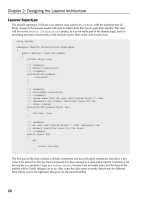
The output of the application looks like Figure 2.9. The application draws a line, a rectangle, and some ellipses with different colors.
Figure 2.9. Your first GDI+ application
This document was created by an unregistered ChmMagic, please go to to register it. Thanks.
Congratulations! You have finished the first step toward becoming a GDI+ expert. Now you can write simple graphics applications in Visual
Studio .NET.
[ Team LiB ]
This document was created by an unregistered ChmMagic, please go to to register it. Thanks.
[ Team LiB ]
2.4 Some Basic GDI+ Objects
In previous sections we discussed the steps required to write a simple graphics application using Visual Studio .NET. Before we move on to
the next chapter, let's discuss some basic GDI+ objects, such as the color-, point-, and rectangle-related structures provided by the .NET
Framework library. Understanding these structures is very important because they are used throughout the book.
2.4.1 The Color Structure
You may have noticed that we used the Color structure in our previous example. The Color structure represents a GDI+ ARGB
(alpha-red-green-blue) color. This class contains a static property for almost every possible color. For example, Color.Black and Color.Red
represent black and red, respectively. Besides these static properties, this structure has the additional properties defined in Table 2.1.
IsKnownColor, IsNamedColor and IsSystemColor represent members of the KnownColor enumeration, which again defines almost every color
as a member.
Table 2.2 describes the methods of the Color structure.
Table 2.1. Color properties
PropertyDescription
Red, Blue, Green, Aqua, Azure, and
so on
A specified color static property for almost every color.
A
Returns the alpha component value in a Color structure. We discuss alpha in color-related sections
in later chapters.
R
Returns the red component value in a Color structure.
G
Returns the green component value in a Color structure.
B
Returns the blue component value in a Color structure.
IsEmpty
Indicates whether a Color structure is uninitialized.
IsKnownColor
Indicates whether a color is predefined.
IsNamedColor
Indicates whether a color is predefined.
IsSystemColor
Indicates whether a color is a system color.
Name
Returns the name of the color.
This document was created by an unregistered ChmMagic, please go to to register it. Thanks.
Table 2.2. Color methods
MethodDescription
FromArgb
Creates a Color structure from the four 8-bit ARGB component (alpha-red-green-blue) values.
FromKnownColor
Creates a Color structure from the specified predefined color.
FromName
Creates a Color structure from the specified name of a predefined color.
GetBrightness
Returns the hue-saturation-brightness (HSB) brightness value of this Color structure.
GetHue
Returns the HSB hue value, in degrees, of this Color structure.
GetSaturation
Returns the HSB saturation value of this Color structure.
ToArgb
Returns the 32-bit ARGB value of this Color structure.
ToKnownColor
Returns the KnownColor value of this Color structure.
2.4.2 The Point and PointF Structures
In GDI+, the Point structure represents an ordered pair of integer x- and y-coordinates that define a point in a two-dimensional plane. The Point
structure's constructor initializes a new instance of the Point structure. The Point constructor has three overloaded forms that allow you to
create a Point object from an integer, a Size object, or two integers as follows:
public Point(int);1.
public Point(Size);2.
public Point(int, int);3.
The following code snippet creates Point objects using all three forms of the constructor:
Point pt1 = new Point(10);
Point pt2 = new Point( new Size(20, 20) );
Point pt3 = new Point(30, 30);
The PointF structure is similar to the Point structure, but it uses floating point values instead of integers. Unlike the Point structure, PointF has
only one constructor, which takes two floating point values as x- and y-coordinates.
PointF pt3 = new PointF(30.0f, 30.0f);
Both the Point and the PointF structures define three properties: IsEmpty, X, and Y. The IsEmpty property returns true if a point is empty, which
means that both X and Y values are zero; otherwise it returns false. The X and Y properties return the x- and y-coordinates of a point,
respectively. The Empty static field of the Point structure creates a new point with X and Y values set to zero.
Listing 2.3 creates a point with zero X and Y values using Point.Empty and assigns new coordinate values using the X and Y properties. This
This document was created by an unregistered ChmMagic, please go to to register it. Thanks.
example creates a Graphics object using the Graphics.FromHwnd method and returns the graphics surface for a form. The
Graphics.FromHwnd method creates a Graphics object from a window handle, which we pass as this.Handle. The DrawLine method draws a
line starting from the first point to the second point using the defined pen. You can test this code on a button or a menu click event handler.
Listing 2.3 Creating Point objects
// Create a new Point object
Point pt = new Point(50, 50);
// Create a new point using Point.Empty
Point newPoint = Point.Empty;
// Set X and Y properties of Point
newPoint.X = 100;
newPoint.Y = 200;
// Create a Graphics object from the
// current form's handle
Graphics g = Graphics.FromHwnd(this.Handle);
// Create a new pen with color blue
// and width = 4
Pen pn = new Pen(Color.Blue, 4);
// Draw a line from point pt to
// new point
g.DrawLine(pn, pt, newPoint);
// Dispose of Pen and Graphics objects
pn.Dispose();
g.Dispose();
Figure 2.10 shows the output of Listing 2.3. The program draws a line from point 1 to point 2. The "Point" text in this figure is a menu item.
Figure 2.10. Using Point to draw a line
Like the Point structure, PointF can also use Empty, X, and Y properties, as shown in Listing 2.4. You can test this code on a button or a menu
click event handler.
This document was created by an unregistered ChmMagic, please go to to register it. Thanks.
Listing 2.4 Creating PointF objects
// Create a new PointF object
PointF pt = new PointF(50.0F, 50.0F);
// Create a new point using PointF.Empty
PointF newPoint = PointF.Empty;
// Set X and Y properties of PointF
newPoint.X = 100.0F;
newPoint.Y = 200.0F;
// Create a Graphics object from the
// current form's handle
Graphics g = Graphics.FromHwnd(this.Handle);
// Create a new pen with color blue
// and width = 4
Pen pn = new Pen(Color.Blue, 4);
// Draw a line from point pt to
// new point
g.DrawLine(pn, pt, newPoint);
// Dispose of Pen and Graphics objects
pn.Dispose();
g.Dispose();
Figure 2.11 shows the output of Listing 2.4. It is identical to Figure 2.10.
Figure 2.11. Using PointF to draw a line
The Point structure also defines methods to convert from PointF to Point. The Ceiling method of the Point structure converts a PointF object to
a Point object by rounding off the values of the PointF object to the next higher integer values. The Round method converts a PointF object to
Point by rounding floating values to the nearest integer values. The Truncate method converts a PointF object to Point by truncating the floating
values to integers. Listing 2.5 shows how to use the Ceiling, Round, and Truncate methods. You can test this code on a button or a menu click
event handler.
This document was created by an unregistered ChmMagic, please go to to register it. Thanks.
Listing 2.5 Using the Ceiling, Round, and Truncate methods of Point
// Create three points
PointF pt1 = new PointF(30.6f, 30.8f);
PointF pt2 = new PointF(50.3f, 60.7f);
PointF pt3 = new PointF(110.3f, 80.5f);
// Call Ceiling, Round, and Truncate methods
// and return new points
Point pt4 = Point.Ceiling(pt1);
Point pt5 = Point.Round(pt2);
Point pt6 = Point.Truncate(pt3);
// Display results
MessageBox.Show("Value of pt4: " +pt4.ToString());
MessageBox.Show("Value of pt5: " +pt5.ToString());
MessageBox.Show("Value of pt6: " +pt6.ToString());
The Point structure also defines addition, equality, inequality, subtraction, Point-to-Size, and Point-to-PointF conversion operators. Listing 2.6
shows how to add and subtract a Size object from a Point object, convert from Point to PointF, and convert from a Point object to a Size object.
You can test this code on a button or a menu click event handler.
Listing 2.6 Some Point and PointF conversions
/ Create a Size object
Size sz = new Size(12, 12);
// Create a Point object
Point pt = new Point(20, 20);
// Add point and size and copy to point
pt = pt+sz;
MessageBox.Show("Addition :"+ pt.ToString());
// Subtract point and size
pt = pt-sz;
MessageBox.Show("Subtraction :"+ pt.ToString());
// Create a PointF object from Point
PointF ptf = pt;
MessageBox.Show("PointF :"+ pt.ToString());
// Convert Point to Size
sz = (Size)pt;
MessageBox.Show("Size :"+ sz.Width.ToString()
+","+ sz.Height.ToString() );
2.4.3 The Rectangle and RectangleF Structures
The Rectangle and RectangleF structures represent a rectangle in GDI+. A Rectangle structure stores the top left corner and height and width
of a rectangular region. You can create a Rectangle object from Point and Size objects or by using four integer values as starting and ending
coordinates of the rectangle.
The Rectangle and RectangleF structures provide properties that can be used to get the height, width, and position of the rectangle. Table 2.3
describes the properties of the Rectangle and RectangleF structures.
This document was created by an unregistered ChmMagic, please go to to register it. Thanks.
Listing 2.7 Using Rectangle properties
// Create Point, Size, and Rectangle objects
Point pt = new Point(10, 10);
Size sz = new Size(60, 40);
Rectangle rect1 = Rectangle.Empty;
Rectangle rect2 = new Rectangle(20, 30, 30, 10);
// Set Rectangle properties
if (rect1.IsEmpty)
{
rect1.Location = pt;
rect1.Width = sz.Width;
rect1.Height = sz.Height;
}
// Get Rectangle properties
string str = "Location:"+ rect1.Location.ToString();
str += ", X:" +rect1.X.ToString();
str += ", Y:"+ rect1.Y.ToString();
str += ", Left:"+ rect1.Left.ToString();
str += ", Right:"+ rect1.Right.ToString();
str += ", Top:"+ rect1.Top.ToString();
str += ", Bottom:"+ rect1.Bottom.ToString();
MessageBox.Show(str);
Table 2.3. Rectangle and RectangleF properties
PropertyDescription
Bottom
Returns the y-coordinate of the bottom edge.
Height
Represents the rectangle's height.
IsEmpty
Returns true if all of the rectangle's values (starting point, height, and width) are zero; otherwise returns false.
Left
Returns the x-coordinate of the left edge.
Location
Represents the coordinates of the upper left corner.
Right
Returns the x-coordinate of the right edge.
Size
Represents the size of a rectangle.
Top
Returns the y-coordinate of the top edge.
Width
Represents the width of a rectangle.
X
Represents the x-coordinate of the upper left corner.
Y
Represents the y-coordinate of the upper left corner.
Listing 2.8 uses three different methods to create three Rectangle objects. The first method creates a Rectangle object by using a Point and a
Size. The second and third methods create a Rectangle by using four integer values as the starting x- and y-coordinates and the width and
height of the rectangle. After creating the rectangles, the program creates pen and brush objects using the Pen and SolidBrush classes and
calls the fill and draw methods of Graphics to draw and fill the rectangles. Finally, we dispose of the objects. You can test this code on a
This document was created by an unregistered ChmMagic, please go to to register it. Thanks.
button or a menu click event handler.
Listing 2.8 Creating Rectangle objects
// Create a Graphics object
Graphics g = this.CreateGraphics();
int x = 40;
int y = 40;
int height = 120;
int width = 120;
// Create a Point object
Point pt = new Point(80, 80);
// Create a Size object
Size sz = new Size(100, 100);
// Create a rectangle from Point and Size
Rectangle rect1 = new Rectangle(pt, sz);
// Create a rectangle from integers
Rectangle rect2 =
new Rectangle(x, y, width, height);
// Create a rectangle from direct integers
Rectangle rect3 =
new Rectangle(10, 10, 180, 180);
// Create pens and brushes
Pen redPen = new Pen(Color.Red, 2);
SolidBrush greenBrush =
new SolidBrush(Color.Blue);
SolidBrush blueBrush =
new SolidBrush(Color.Green);
// Draw and fill rectangles
g.DrawRectangle(redPen, rect3);
g.FillRectangle(blueBrush, rect2);
g.FillRectangle(greenBrush, rect1);
// Dispose of the objects
redPen.Dispose();
blueBrush.Dispose();
greenBrush.Dispose();
g.Dispose();
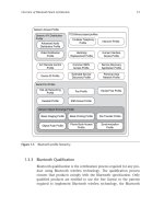
Figure 2.12 shows the output from Listing 2.8: three different rectangles.
Figure 2.12. Using Rectangle to create rectangles
This document was created by an unregistered ChmMagic, please go to to register it. Thanks.
You can create a RectangleF object in a similar way. The only difference is that RectangleF takes floating point arguments instead of integers,
SizeF instead of Size, and PointF instead of Point. Listing 2.9 creates RectangleF objects from SizeF, PointF, Size, and Point objects. You can
test this code on a button or a menu click event handler.
Listing 2.9 Creating RectangleF objects
// Create a Graphics object
Graphics g = this.CreateGraphics();
float x = 40.0f;
float y = 40.0f;
float height = 120.0f;
float width = 120.0f;
// Create a PointF object
PointF pt = new PointF(80.0f, 80.0f);
// Create a SizeF object
SizeF sz = new SizeF(100.0f, 100.0f);
// Create a rectangle from PointF and SizeF
RectangleF rect1 = new RectangleF(pt, sz);
// Create a rectangle from integers
RectangleF rect2 =
new RectangleF(x, y, width, height);
// Create a rectangle from direct integers
RectangleF rect3 =
new RectangleF(10.0f, 10.0f, 180.0f, 180.0f);
// Create pens and brushes
Pen redPen = new Pen(Color.Red, 2);
SolidBrush greenBrush =
new SolidBrush(Color.Blue);
SolidBrush blueBrush =
new SolidBrush(Color.Green);
// Draw and fill rectangles
g.DrawRectangle(redPen, rect3.X, rect3.Y,
rect3.Width, rect3.Height);
g.FillRectangle(blueBrush, rect2);
g.FillRectangle(greenBrush, rect1);
// Dispose of objects
redPen.Dispose();
blueBrush.Dispose();
greenBrush.Dispose();
g.Dispose();
Figure 2.13 shows the output from Listing 2.9: three different rectangles, as in Figure 2.12.
This document was created by an unregistered ChmMagic, please go to to register it. Thanks.
Figure 2.13. Using RectangleF to create rectangles
Table 2.4. Rectangle and RectangleF methods
MethodDescription
Ceiling
Converts a RectangleF object to a Rectangle object by rounding the RectangleF values to the next higher integer values.
Contains
Determines if the specified point is contained within the rectangular region of a rectangle.
FromLTRB
Creates a rectangle with the specified edge locations.
Inflate
Creates and returns an inflated copy of a rectangle.
Intersect
Replaces a rectangle with the intersection of itself and another rectangle.
IntersectsWith
Determines if a specified rectangle intersects with rect.
Offset
Adjusts the location of a specified rectangle by the specified amount.
Round
Converts a RectangleF object to a Rectangle object by rounding the RectangleF values to the nearest integer values.
Truncate
Converts a RectangleF object to a Rectangle object by truncating the RectangleF values.
Union
Returns a rectangle that contains the union of two Rectangle structures.
Like the Point and PointF structures, Rectangle and RectangleF define Ceiling, Round, and Truncate methods. These methods are described
in Table 2.4. Listing 2.10 shows how to use these methods.
This document was created by an unregistered ChmMagic, please go to to register it. Thanks.
Listing 2.10 Using the Round, Truncate, Union, Inflate, Ceiling, and Intersect methods of Rectangle
// Create a Graphics object
Graphics g = this.CreateGraphics();
// Create PointF, SizeF, and RectangleF objects
PointF pt = new PointF(30.8f, 20.7f);
SizeF sz = new SizeF(60.0f, 40.0f);
RectangleF rect2 =
new RectangleF(40.2f, 40.6f, 100.5f, 100.0f);
RectangleF rect1 = new RectangleF(pt, sz);
Rectangle rect3 = Rectangle.Ceiling(rect1);
Rectangle rect4 = Rectangle.Truncate(rect1);
Rectangle rect5 = Rectangle.Round(rect2);
// Draw rectangles
g.DrawRectangle(Pens.Black, rect3);
g.DrawRectangle(Pens.Red, rect5);
// Intersect rectangles
Rectangle isectRect =
Rectangle.Intersect(rect3, rect5);
// Fill new rectangle
g.FillRectangle(
new SolidBrush(Color.Blue), isectRect);
// Create a Size object
Size inflateSize = new Size(0, 40);
// Inflate rectangle
isectRect.Inflate(inflateSize);
// Draw new rectangle
g.DrawRectangle(Pens.Blue, isectRect);
// Set Rectangle properties
rect4 = Rectangle.Empty;
rect4.Location = new Point(50, 50);
rect4.X = 30;
rect4.Y = 40;
// Union two rectangles
Rectangle unionRect =
Rectangle.Union(rect4, rect5);
// Draw new rectangle
g.DrawRectangle(Pens.Green, unionRect);
// Dispose of the Graphics object
g.Dispose();
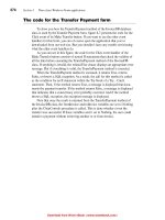
Figure 2.14 shows the output from Listing 2.10.
Figure 2.14. Using the Round, Truncate, Union, Inflate, Ceiling, and Intersect methods of Rectangle
This document was created by an unregistered ChmMagic, please go to to register it. Thanks.
2.4.4 The Size and SizeF Structures
The Size and SizeF structures represent the size of a rectangular area. Like Point/PointF and Rectangle/RectangleF, Size and SizeF also each
have an Empty static field, which creates a Size object with zero height and zero width. The only difference between Size and SizeF is that Size
uses integer values and SizeF uses floating point values.
You can create Size and SizeF objects by passing the width and height of the Point and PointF objects as constructor arguments, respectively.
Listing 2.11 shows different ways to create Size and SizeF objects.
Listing 2.11 Creating Size and SizeF objects
Point pt1 = new Point(20, 40);
PointF pt2 = new PointF(50.0f, 80.0f);
Size sz1 = new Size(pt1);
SizeF sz2 = new SizeF(pt2);
Size sz3 = new Size(100, 150);
SizeF sz4 = new SizeF(12.5f, 87.6f);
The Height and Width properties represent the height and width, respectively, of the area represented by the Size and SizeF structures. The
IsEmpty property returns true if Size has zero height and zero width; otherwise it returns false.
Like the Point/PointF and Rectangle/RectangleF structures, Size and SizeF have Ceiling, Truncate, and Round static methods. Each method
can convert a SizeF object to a Size object: the Ceiling method, by rounding the values of the Size structure to the next higher integer values;
the Round method, by rounding the values of the Size structure to the nearest integer values; and the Truncate method, by truncating the
values to the next lower integer values.
Listing 2.12 shows the use of the Ceiling, Round and Truncate methods. You can test this code on a button or a menu click event handler.
Listing 2.12 Using the Ceiling, Round, and Truncate methods of Size and SizeF
PointF pt1 = new PointF(30.6f, 30.8f);
PointF pt2 = new PointF(50.3f, 60.7f);
PointF pt3 = new PointF(110.3f, 80.5f);
This document was created by an unregistered ChmMagic, please go to to register it. Thanks.
SizeF sz1 = new SizeF(pt1);
SizeF sz2 = new SizeF(pt2);
SizeF sz3 = new SizeF(pt3);
Size sz4 = Size.Ceiling(sz1);
Size sz5 = Size.Round(sz2);
Size sz6 = Size.Truncate(sz3);
[ Team LiB ]
This document was created by an unregistered ChmMagic, please go to to register it. Thanks.
[ Team LiB ]
SUMMARY
Before you write a graphics application, a basic understanding of drawing surfaces and coordinate systems is a must. This chapter began
with the basics of the drawing surfaces and the coordinate system, describing how drawing surfaces and coordinate systems are represented
in GDI+ and how the GDI+ coordinate system differs from other coordinate systems.
Before using any GDI+-related classes defined in the .NET Framework library, you must reference System.Drawing and its subnamespaces.
In this chapter you learned how to add references to the GDI+ library and how to import the GDI+-related namespaces into your application.
After adding a reference to the GDI+ library and namespaces to the application, the next step is to get the Graphics object. There are several
ways to get a Graphics object in an application. This chapter discussed three different ways, and then showed how to use the Graphics class
methods to draw and fill lines, rectangles, and ellipses. You also learned to dispose of objects when you're finished with them.
Finally, we covered some basic GDI+ structures—including Color, Rectangle, RectangleF, Point, PointF, Size, and SizeF—describing their
members and how to use them in your applications.
You should now be able to write simple graphics applications using GDI+.
Chapter 3 is all about the Graphics class and will demonstrate how quickly you can write real-world applications. By the end of Chapter 3, you
will be able to write your own 2D paint application similar to Microsoft's PaintBrush, using your newly acquired GDI+ skills.
[ Team LiB ]
This document was created by an unregistered ChmMagic, please go to to register it. Thanks.
[ Team LiB ]
Chapter 3. The Graphics Class
Graphics objects are the heart of GDI+. They are represented by the Graphics class, which defines methods and properties to draw and fill
graphics objects. Whenever an application needs to draw or paint something, it has to use the Graphics object. Hence, understanding the
Graphics class, its methods, and its properties is very important. We will use Graphics methods and properties in all the chapters that follow.
Specifically, in this chapter we will discuss the methods and properties of the Graphics class, and how to use them in real-world applications,
including line charts, pie charts, and our GDI+Painter application. GDI+Painter is similar to the PaintBrush application, which allows you to
draw simple graphics objects such as lines, rectangles, and circles and save the images as bitmaps.
[ Team LiB ]
This document was created by an unregistered ChmMagic, please go to to register it. Thanks.
[ Team LiB ]
3.1 Graphics Class Properties
The Graphics class provides a long list of properties (see Table 3.1) and methods. We will discuss and use these properties and methods in
this and following chapters.
Table 3.1. Graphics properties
PropertyDescription
Clip
Gets and sets a Region type that limits the drawing region of the Graphics object.
ClipBounds
Returns a RectangleF structure that bounds the clipping region of this Graphics object. Supports read-only access.
CompositingMode
Returns a value of type CompositingMode enumeration representing how composite images are drawn to the
Graphics object.
CompositingQuality
Gets and sets the rendering quality (directly proportional to the visual quality of the output and inversely proportional
to the rendering time) of composite images, represented by the CompositingQuality enumeration.
DpiX
Returns the horizontal resolution (dots per inch) of a Graphics object.
DpiY
Returns the vertical resolution (dots per inch) of a Graphics object.
InterpolationMode
Gets and sets the interpolation mode (which determines intermediate values between two endpoints), represented
by the InterpolationMode enumerator.
IsClipEmpty
Returns a value indicating whether the clipping region of a Graphics object is empty. When there is no clipping, this
property returns false.
IsVisibleClipEmpty
Returns a value indicating whether the visible clipping region of a Graphics object is empty.
PageScale
Gets and sets a value for scaling between world units and page units for this Graphics object.
PageUnit
Gets and sets a value that represents the unit of measure for page coordinates.
PixelOffsetMode
Gets and sets a value for the pixel offset mode (PixelOffsetMode enumeration).
RenderingOrigin
Represents the rendering origin of a Graphics object for dithering and hatch brushes.
SmoothingMode
Gets and sets the smoothing mode of a Graphics object (SmoothingMode enumeration). Does not affect text.
Smoothing modes include high quality, high speed, and anti-aliasing.
TextContrast
Gets and sets the gamma correction value for rendering anti-aliased and ClearType text values, ranging from 0 to
12. The default is 4.
TextRenderingHint
Gets and sets the text rendering quality (TextRenderingHint enumeration). Affects only text drawn on the Graphics
object.
Transform
Gets and sets the world transformation matrix (transformation is the process of converting graphics objects from one
state to another). The transformation state is represented by a transformation matrix.
This document was created by an unregistered ChmMagic, please go to to register it. Thanks.
PropertyDescription
VisibleClipBounds
Gets and sets the visible clipping region of the Graphics object (the intersection of the clipping region of the Graphics
object and the clipping region of the window).
[ Team LiB ]
This document was created by an unregistered ChmMagic, please go to to register it. Thanks.
[ Team LiB ]
3.2 Graphics Class Methods
We can divide Graphics class methods into three categories: draw, fill, and miscellaneous. Draw methods are used to draw lines, curves, and
outer boundaries of closed curves and images. Fill methods fill the interior area of graphics objects. There are also a few miscellaneous
methods that fall in neither category—for example, MeasureString and Clear.
3.2.1 Draw Methods
The draw methods of the Graphics class are used to draw lines, curves, and outer boundaries of closed curves and images. Table 3.2 lists the
draw methods of the Graphics class.
3.2.1.1 Drawing Lines
The DrawLine method draws a line beween two points specified by a pair of coordinates. DrawLines draws a series of lines using an array of
points.
This document was created by an unregistered ChmMagic, please go to to register it. Thanks.