gdi programming with c sharp phần 5 pdf
Bạn đang xem bản rút gọn của tài liệu. Xem và tải ngay bản đầy đủ của tài liệu tại đây (6.5 MB, 70 trang )
Rectangle rect1 =
new Rectangle(20, 20, 60, 80);
Rectangle rect2 =
new Rectangle(50, 30, 60, 80);
Region rgn1 = new Region(rect1);
Region rgn2 = new Region(rect2);
// If region is not empty, empty it
if (! rgn1.IsEmpty(g))
rgn1.MakeEmpty();
// If region is not infinite, make it infinite
if (! rgn2.IsInfinite(g))
rgn2.MakeInfinite();
// Get bounds of the infinite region
RectangleF rect = rgn2.GetBounds(g);
// Display
MessageBox.Show(rect.ToString());
// Fill the region
g.FillRegion(Brushes.Red, rgn2);
// Dispose of object
g.Dispose();
An infinite region's starting coordinates are negative numbers, and its height and width are large positive numbers, as Figure 6.10 shows.
Using FillRegion on an infinite region fills the entire form.
Figure 6.10. Bounds of an infinite region
[ Team LiB ]
This document was created by an unregistered ChmMagic, please go to to register it. Thanks.
[ Team LiB ]
6.3 Regions and Clipping
As we discussed in Chapter 3, the Graphics class provides methods to clip regions. Using these methods, an application can restrict where
graphics objects are drawn. One major use of clipping regions is to repaint only part of a control. In some cases painting an entire form is
costly in terms of time and memory resources. Clipping plays a vital role by painting only the desired area. The Graphics class provides the
SetClip, ResetClip, IntersectClip, ExcludeClip, and TranslateClip methods to use in clipping operations.
ExcludeClip excludes the area specified by an argument of type Rectangle or a Region and updates the clipping region. Listing 6.11 fills a
rectangle, excluding one small rectangle and a region.
Listing 6.11 Using ExcludeClip to clip regions
// Create a Graphics object
Graphics g = this.CreateGraphics();
g.Clear(this.BackColor);
// Create rectangles
Rectangle rect1 = new Rectangle(20, 20, 60, 80);
Rectangle rect2 = new Rectangle(100, 100, 30, 40);
// Create a region
Region rgn1 = new Region(rect2);
// Exclude clip
g.ExcludeClip(rect1);
g.ExcludeClip(rgn1);
// Fill rectangle
g.FillRectangle(Brushes.Red, 0, 0, 200, 200);
// Dispose of object
g.Dispose();
Figure 6.11 shows output from Listing 6.11. The small rectangle and small region are not updated.
Figure 6.11. ExcludeClip output
This document was created by an unregistered ChmMagic, please go to to register it. Thanks.
SetClip sets the clipping region of a Graphics object. This method has many overloaded forms and takes parameters of type Rectangle,
RectangleF, Region, GraphicsPath, and Graphics with or without the CombineMode enumeration. The CombineMode enumeration defines
how different clipping regions can be combined (see Table 6.2).
The ResetClip method resets the clipping region to infinity. Listing 6.12 uses the SetClip, ResetClip, and IntersectClip methods.
Listing 6.12 Using the SetClip, ResetClip, and IntersectClip methods
// Create a Graphics object
Graphics g = this.CreateGraphics();
g.Clear(this.BackColor);
// Create rectangles and regions
Rectangle rect1 = new Rectangle(20, 20, 200, 200);
Rectangle rect2 = new Rectangle(100, 100, 200, 200);
Region rgn1 = new Region(rect1);
Region rgn2 = new Region(rect2);
// Call SetClip
g.SetClip(rgn1, CombineMode.Exclude);
// Call IntersectClip
g.IntersectClip(rgn2);
// Fill rectangle
g.FillRectangle(Brushes.Red, 0, 0, 300, 300);
// Call ResetClip
g.ResetClip();
// Draw rectangles
g.DrawRectangle(Pens.Green, rect1);
g.DrawRectangle(Pens.Yellow, rect2);
// Dispose of object
g.Dispose();
This document was created by an unregistered ChmMagic, please go to to register it. Thanks.
Table 6.2. CombineMode members
MemberDescription
Complement
The existing region is replaced by the result of the existing region being removed from the new region.
Exclude
The existing region is replaced by the result of the new region being removed from the existing region.
Intersect
Two clipping regions are combined, and the result is their intersection.
Replace
One clipping region replaces the other.
Union
Two clipping regions are combined, and the result is their union.
Xor
Two clipping regions are combined, and the result is their union minus their intersection.
Note
The CombineMode enumeration is defined in the System.Drawing.Drawing2D namespace.
Figure 6.12 shows the output from Listing 6.12.
Figure 6.12. Using Clip methods
This document was created by an unregistered ChmMagic, please go to to register it. Thanks.
TranslateClip translates the clipping region as specified. Listing 6.13 uses the TranslateClip method to translate a region by 20 and 30 points.
Listing 6.13 Using TranslateClip to translate a region
// Create a Graphics object
Graphics g = this.CreateGraphics();
g.Clear(this.BackColor);
// Create a RectangleF rectangle
RectangleF rect1 =
new RectangleF(20.0f, 20.0f, 200.0f, 200.0f);
// Create a region
Region rgn1 = new Region(rect1);
// Call SetClip
g.SetClip(rgn1, CombineMode.Exclude);
float h = 20.0f;
float w = 30.0f;
// Call TranslateClip with h and w
g.TranslateClip(h, w);
// Fill rectangle
g.FillRectangle(Brushes.Green, 20, 20, 300, 300);
Figure 6.13 shows the output from Listing 6.13.
Figure 6.13. Using TranslateClip
[ Team LiB ]
This document was created by an unregistered ChmMagic, please go to to register it. Thanks.
[ Team LiB ]
6.4 Clipping Regions Example
Listing 6.14 uses Xor to clip regions.
Listing 6.14 Using the Xor method
Pen pen = new Pen(Color.Red, 5);
SolidBrush brush = new SolidBrush(Color.Red);
Rectangle rect1 = new Rectangle(50, 0, 50, 150);
Rectangle rect2 = new Rectangle(0, 50, 150, 50);
Region region = new Region(rect1);
region.Xor(rect2);
g.FillRegion(brush, region);
Figure 6.14 shows the output from Listing 6.14.
Figure 6.14. Result of the Xor method
Now if we replace Xor with Union:
region.Union(rect2);
the new output looks like Figure 6.15.
This document was created by an unregistered ChmMagic, please go to to register it. Thanks.
Figure 6.15. Result of the Union method
Now let's replace Union with Exclude:
region.Exclude(rect2);
The output looks like Figure 6.16.
Figure 6.16. Result of the Exclude method
If we use the Intersect method:
This document was created by an unregistered ChmMagic, please go to to register it. Thanks.
region.Intersect(rect2);
the output looks like Figure 6.17.
Figure 6.17. Result of the Intersect method
[ Team LiB ]
This document was created by an unregistered ChmMagic, please go to to register it. Thanks.
[ Team LiB ]
This document was created by an unregistered ChmMagic, please go to to register it. Thanks.
6.5 Regions, Nonrectangular Forms, and Controls
When we're writing Windows applications with drawing functionality, it becomes important to understand the roles of regions, client areas, and
nonclient areas. This section will describe an exciting and wonderful use of regions.
Figure 6.18 shows a typical rectangular form. As you can see, the title bar area usually contains the title of the form, as well as minimize,
maximize, and close buttons. This is the nonclient area; the rest of the form is the client area. Graphics objects can be drawn only in the client
area. The combination of both client and nonclient areas is the default region of a form.
Figure 6.18. Client and nonclient areas of a form
What exactly is a region? A region is a collection of pixels that represents part of a control. GDI+ is responsible only for drawing the region
associated with a window (a form or control). The default region of a window includes both client and nonclient areas, so GDI+ draws the
entire window.
However, you can force the operating system to display only part of a window. This is where regions are useful.
6.5.1 The Application
This section will show you the importance of regions and how you can use them in real-world applications.
Have you ever thought about writing nonrectangular forms or controls? How about writing circular, triangular, or polygonal forms, buttons,
This document was created by an unregistered ChmMagic, please go to to register it. Thanks.
labels, or text boxes? Our example is a Windows application in which the user can select the shape of the form. The user will have options to
change the default rectangular form to a circular, triangular, or polygonal form. You will also learn how to create nonrectangular controls such
as buttons.
How can we write nonrectangular forms and controls? GDI+ draws only the regions associated with a form or a control. But setting a
nonrectangular region should do the trick. This is what we will do in our application. One of the nonrectangular forms of the final application
might look like Figure 6.19. As you can see, this technique can be used to build cool-looking Windows applications.
Figure 6.19. A nonrectangular form and controls
6.5.2 Coding
In Windows Forms, every control, including a form, is derived from the Control class. The Region property of the control class represents the
region of control. If you set the Region property of a control, only the area covered by that region will be visible to the user. Section 6.5.2.1
through 6.5.2.6 describe the steps involved in writing code for nonrectangular shapes.
6.5.2.1 Step 1: Create the Application
We create a Windows application, put three controls on the form, and change the Text properties of the buttons. We also add a context menu
and four menu items, as Figure 6.20 shows. In addition, we add menu and button click event handlers.
Figure 6.20. The nonrectangular forms application
This document was created by an unregistered ChmMagic, please go to to register it. Thanks.
6.5.2.2 Step 2: Add the Shape Class
Now we add a class to the project. Our class name is Shape, as Listing 6.15 shows. We add two methods to this class: GetPolyRegion and
GetRectRegion. Both of these methods return a Region object. The GetPolyRegion method takes an array of Point objects as its only
argument. We create a graphics path from the points by calling AddPolygon. After that we create a region from the path and return it. See
Chapters 3 and 9 for more about the GraphicsPath class. Similarly, we create a region from a rectangle in the GetRectRegion method.
Listing 6.15 The Shape class
// The Shape class contains the functionality
// of shaped controls
public class Shape
{
public Shape()
{
}
public Region GetPolyRegion(Point[] pts)
{
// Create a graphics path
GraphicsPath path =
new GraphicsPath(FillMode.Alternate);
path.AddPolygon(pts);
// Create a Region object from the path
// and set it as the form's region
Region rgn = new Region(path);
return rgn;
}
public Region GetRectRegion(Rectangle rct)
This document was created by an unregistered ChmMagic, please go to to register it. Thanks.
{
// Create a graphics path
GraphicsPath path =
new GraphicsPath(FillMode.Alternate);
path.AddEllipse(rct);
// Create a Region object from the path
// and set it as the form's region
Region rgn = new Region(path);
return rgn;
}
}
6.5.2.3 Step 3: Load the Context Menu
Now we load the context menu on the right mouse click of the form. In Listing 6.16, we set the ContextMenu property of the form as the
context menu control.
Listing 6.16 The mouse-down click event handler
private void Form1_MouseDown(object sender,
System.Windows.Forms.MouseEventArgs e)
{
if(e.Button == MouseButtons.Right)
{
this.ContextMenu = this.contextMenu1;
}
}
6.5.2.4 Step 4: Call the Shape Class Methods
Now we call GetRectRegion and GetPolyRegion from the context menu click event handlers to get the region for a rectangle or a polygon.
After getting a Region object corresponding to a rectangle or a polygon, we just need to set the Region property of the form. Listing 6.17 shows
the code for the context menu click event handlers.
Listing 6.17 Menu item click event handlers
private void CircleMenu_Click(object sender,
System.EventArgs e)
{
// Create a rectangle
Rectangle rect =
new Rectangle(50, 0, 300, 300);
// Create a Shape object and call
// the GetRectRegion method
Shape shp = new Shape();
This document was created by an unregistered ChmMagic, please go to to register it. Thanks.
this.Region = shp.GetRectRegion(rect);
this.BackColor = Color.BurlyWood;
}
private void RectMenu_Click(object sender,
System.EventArgs e)
{
// A Points array for a rectangle
// Same points as the original form
Point[] pts =
{
new Point(0, 0),
new Point(0, originalSize.Height),
new Point(originalSize.Width, originalSize.Height),
new Point(originalSize.Width, 0)
};
// Create a Shape object and call
// the GetPolyRegion method
Shape shp = new Shape();
this.Region = shp.GetPolyRegion(pts);
// Set background color
this.BackColor = Color.DarkGoldenrod;
}
private void TriangleMenu_Click(object sender,
System.EventArgs e)
{
// Add three lines to the path representing
// three sides of a triangle
Point[] pts =
{
new Point(50, 0),
new Point(0,300),
new Point(300, 300),
new Point(50, 0)
};
this.BackColor = Color.CornflowerBlue;
// Create a Shape object and call
// the GetPolyRegion method
Shape shp = new Shape();
this.Region = shp.GetPolyRegion(pts);
}
The code in Listing 6.18 for the Close menu item simply closes the form.
Listing 6.18 The Close menu click event handler
private void CloseMenu_Click(object sender,
System.EventArgs e)
{
this.Close();
}
This document was created by an unregistered ChmMagic, please go to to register it. Thanks.
6.5.2.5 Step 5: Display Nonrectangular Shapes
Using similar methods, you can set the Region property of controls such as Button or TextBox to display nonrectangular shapes. If you don't
want to use the Shape class, you can directly set the Region property of a control. Listing 6.19 sets the Region properties of three buttons. We
write this code on the form's load event handler.
Listing 6.19 Setting the Region properties of buttons
originalSize = this.Size;
// Create a Region object from the path
GraphicsPath path1 =
new GraphicsPath(FillMode.Alternate);
path1.AddEllipse(new Rectangle(30, 30,
AudioBtn.Width -60, AudioBtn.Height-60));
AudioBtn.Region = new Region(path1);
GraphicsPath path2 =
new GraphicsPath(FillMode.Alternate);
path2.AddEllipse(new Rectangle(30, 30,
VideoBtn.Width -60, VideoBtn.Height-60));
VideoBtn.Region = new Region(path2);
GraphicsPath path3 =
new GraphicsPath(FillMode.Alternate);
path3.AddEllipse(new Rectangle(20, 20,
VideoBtn.Width -40, VideoBtn.Height-40));
AnimationBtn.Region = new Region(path3);
6.5.2.6 Step 6: Build and Run
The last step is to run the application and right-click on the form. Figure 6.21 shows the result of selecting the Circle menu option.
Figure 6.21. A circular form
This document was created by an unregistered ChmMagic, please go to to register it. Thanks.
Figure 6.22 shows the result of selecting the Triangle menu option.
Figure 6.22. A triangular form
Using this technique, you can build Windows forms and controls of virtually any shape.
[ Team LiB ]
This document was created by an unregistered ChmMagic, please go to to register it. Thanks.
[ Team LiB ]
SUMMARY
In this chapter we discussed some common uses of rectangles and regions. You learned several ways to create Rectangle and RectangleF
objects, and how to use the Round, Truncate, Union, Inflate, Ceiling, and Intersect methods in your applications. After that you saw an
example of a hit test. Then we discussed the Region class and its members, and how to use Complement, Union, Exclude, Xor, and other
methods of the Region class. We also saw a sample of clipping regions. At the end of this chapter we saw an interesting sample application
that uses regions to create nonrectangular forms and controls.
Imaging is a vital part of graphics. GDI+ provides rich imaging functionality. We will cover this functionality in Chapter 7.
[ Team LiB ]
This document was created by an unregistered ChmMagic, please go to to register it. Thanks.
[ Team LiB ]
Chapter 7. Working with Images
In viewing and manipulating images, GDI+ provides significant improvements over its predecessor, GDI. In this chapter we will discuss the
following topics:
Basic imaging-related classes defined in the .NET Framework library
The difference between raster and vector images
The Image class, its properties, and its methods
Writing an image viewer application
Opening and viewing images
Retrieving image properties
Creating thumbnails
Rotating and flipping images
Zooming in and out on images
Saving and skewing images
Changing the resolution and scaling of images
Playing animated images
The Bitmap class, its properties, and its methods
Using the Icon class to work with icons
Drawing transparent images
Using the PictureBox control to draw images
As we said earlier, the graphics-related functionality in the .NET Framework class library is defined in the System.Drawing namespace and its
helper namespaces. The imaging functionality is divided into two categories by separation into two namespaces. Basic imaging functionality is
defined in the System.Drawing namespace; advanced imaging functionality is defined in the System.Drawing.Imaging namespace. This
chapter covers the former; Chapter 8 will focus on the latter.
[ Team LiB ]
This document was created by an unregistered ChmMagic, please go to to register it. Thanks.
[ Team LiB ]
7.1 Raster and Vector Images
The graphics world divides images into two types: raster and vector.
A raster image (also called bitmap) is a collection of one or more pixels. Each pixel of the image can be controlled individually, which means
that each pixel of the image can have a different color or shade. In a raster image that contains a line and a rectangle, the line and rectangle
are each a sequence of pixels. Raster images require higher resolutions and anti-aliasing for a smooth appearance and are best suited for
photographs and images with shading.
A vector image is a collection of one or more vectors. Mathematically, a vector is a combination of a magnitude and a direction, which can be
used to represent the relationships between points, lines, curves, and filled areas. In vector images, a vector is the entity to be controlled.
Each vector can have a separate color or shade. So a vector image with a line and a rectangle is a set of vectors in which each vector has
different properties, such as color or shade. Vector graphics are mathematically described and appear smooth at any size or resolution, and
they are often used by mechanical and architectural engineers.
Vector images can be transformed from one state to another without any loss of data. Transforming raster images, however, may cause data
loss or reduce the quality of images. For example, in the zoomed raster image shown in Figure 7.1, the outer boundary of the image is blurry.
Figure 7.1. A zoomed raster image
In the zoomed vector image of Figure 7.2, however, the outer boundary of the image is sharper.
Figure 7.2. A zoomed vector image
This document was created by an unregistered ChmMagic, please go to to register it. Thanks.
7.1.1 Raster Image Formats
A bitmap is usually stored in an array of bits that specify the color of each pixel in a rectangular array of pixels. The bitmap's height and width
are measured in pixels. The number of bits per pixel specifies the number of colors that can be assigned to that pixel, according to the
equation
N
c
=2
Bp
where
N
c
= the number of colors that each pixel can display
Bp = the number of bits per pixel
For example, if Bp = 8, then N
c
= 2
8
= 256 colors. If Bp = 24, then N
c
= 2
24
= 16,777,216 colors. Table 7.1 shows the number of bits and
number of possible colors that can be assigned to a pixel.
Bitmaps with 1 bit per pixel are called monochrome images. Monochrome images generally store two colors: black and white.
7.1.2 Graphics File Formats
There are many bitmap image formats, including the following:
BMP
GIF
JPEG
EXIF
PNG
TIFF
7.1.2.1 BMP
BMP is a standard Windows format to store device-independent and application-independent bitmap images. The number of bits per pixel (1,
This document was created by an unregistered ChmMagic, please go to to register it. Thanks.
4, 8, 16, 24, 32, or 64) for a given BMP file is specified in a file header. BMP files with 24 bits per pixel are common.
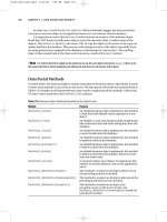
Table 7.1. Number of bits and possible number of colors per pixel
BitsColors
1
2
1
= 2
2
2
2
= 4
4
2
4
= 16
8
2
8
= 256
16
2
16
= 65,536
24
2
24
= 16,777,216
7.1.2.2 GIF
Graphics Interchange Format (GIF) is a common format for images that appear on Web pages. GIF uses Lempel-Ziv-Welch (LZW)
compression to minimize file size. No information is lost in the compression process; a decompressed image is exactly the same as the
original. GIF files can use a maximum of 8 bits per pixel, so they are limited to 256 colors.
7.1.2.3 JPEG
Joint Photographic Experts Group (JPEG) is another popular format used on Web pages. JPEG can store 24 bits per pixel, so it is capable
of displaying more than 16 million colors. Some information is lost during JPEG conversion, but it usually doesn't affect the perceived quality
of the image. JPEG is not a file format; it is a compression scheme. JPEG File Interchange Format (JFIF) is a file format commonly used for
storing and transferring images that have been compressed according to the JPEG scheme.
7.1.2.4 EXIF
Exchangeable Image File (EXIF) is a file format used by digital cameras. It was originally developed by the Japan Electronic Industry
Development Association. The EXIF file contains an image compressed according to the JPEG specification.
7.1.2.5 PNG
This document was created by an unregistered ChmMagic, please go to to register it. Thanks.
Portable Network Graphics (PNG) format provides the advantages of the GIF format but supports greater color depth. PNG files can store
colors with 8, 24, 32, or 48 bits per pixel, and grayscales with 1, 2, 4, 8, or 16 bits per pixel. PNG also supports alpha channel, so it's a
suitable format for storing images that support a high number of colors with transparency.
7.1.2.6 TIFF
Tag Image File Format (TIFF or TIF) can store images with arbitrary color depth, using a variety of compression algorithms. The TIFF format
can be extended as needed by the approval and addition of new tags. This format is used by engineers when they need to add information in
the image itself.
Almost all image file formats can also store metadata related to the image, such as scanner manufacturer, host computer, type of
compression, orientation, samples per pixel, and so on.
[ Team LiB ]
This document was created by an unregistered ChmMagic, please go to to register it. Thanks.
[ Team LiB ]
7.2 Working with Images
Before we write any imaging code, let's explore the .NET Framework library and see what kind of imaging support it offers. The Bitmap class
provides functionality to work with raster images, and the Metafile class provides functionality to work with vector images. Both classes are
inherited from the Image class. In this chapter we will discuss the Image and Bitmap classes and their members. The Metafile class will be
discussed in Chapter 8.
We'll start this discussion with the Image class, which is defined in the System.Drawing namespace. Understanding this class is important
because we will be using its members in our samples throughout this chapter and the next.
The Image class is an abstract base class for the Bitmap, Metafile, and Icon classes. Some common Image class properties (all read-only) are
described in Table 7.2.
The Pixel Format
The pixel format (also known as color depth) defines the number of bits within each pixel. The format also defines the order
of color components within a single pixel of data. In the .NET Framework library, the PixelFormat enumeration represents the
pixel format.
Besides the properties discussed in Table 7.2, the Image class provides methods, which are described in Table 7.3.
7.2.1 An Image Viewer Application
Now we will write an application that will use some of the properties and methods of the Image class. You will learn how to open, view,
manipulate, and save images. The application is a simple image viewer.
This document was created by an unregistered ChmMagic, please go to to register it. Thanks.
Table 7.2. Image class properties
PropertyDescription
Flags
Gets or sets attribute flags for an image.
FrameDimensionsList
Returns an array of GUIDs that represent the dimensions of frames within an image.
Height, WidthReturns the height and width of an image.
HorizontalResolution
Returns the horizontal resolution, in pixels per inch, of an image.
Palette
Gets or sets the color palette used for an image.
PhysicalDimension
Returns the width and height of an image.
PixelFormat
Returns the pixel format for an image.
PropertyIdList
Returns an array of the property IDs stored in an image.
PropertyItems
Returns an array of PropertyItem objects for an image.
RawFormat
Returns the format of an image.
Size
Returns the width and height of an image.
VerticalResolution
Returns the vertical resolution, in pixels per inch, of an image.
To begin:
Use Visual Studio .NET to create a Windows application project called ImageViewer.1.
Add a MainMenu control and some menu items to the form.2.
Change the text of the menu items to File, Open File, Save File, and Exit, and the name of these menu items to FileMenu,
OpenFileMenu, SaveFileMenu, and ExitMenu, respectively. The final form looks like Figure 7.3.
Figure 7.3. A simple image viewer application
3.
This document was created by an unregistered ChmMagic, please go to to register it. Thanks.
Write menu click event handlers for the OpenFileMenu, SaveFileMenu, and ExitMenu items by simply double-clicking on them. 4.
The OpenFileMenu click event handler will allow us to browse and select one image and display it, the SaveFileMenu click event handler will
save the image as a new file name, and the ExitMenu click event handler will simply close the application.
Before we write code for these menu event handlers, let's see how to create an Image object from a file and how to display it using the
DrawImage method of the Graphics class.
This document was created by an unregistered ChmMagic, please go to to register it. Thanks.