KNOWLEDGE-BASED SOFTWARE ENGINEERING phần 2 pps
Bạn đang xem bản rút gọn của tài liệu. Xem và tải ngay bản đầy đủ của tài liệu tại đây (2.31 MB, 34 trang )
A.
Takaci
and M.
Ivanovic
/
Sub-optimal Journey Supported
by
Agents
23
implemented.
The
implementation
is
deeply based
on the
Java package LASSMachine, which
is
a
tool
for
agent programming.
An
agent programmed using
the
package LASSMachine
possesses
its
beliefs, intentions,
services, plans
for
service executions, behaviors,
and
meta-capabilities.
It is
'aware'
of
time
and
it can be
accessed
via
WWW. More detailed description
of
LASSMachine
is
given
in
[1,2,3]
2.1
Travel
Agent
Travel agents communicate with users
and
they have
the
main role
in the
parallel search
for
the
sub-optimal journey
and in the
tickets reservation
process.
Some
of the
travel agent services are:
1.
WEBSERVICE
-
enables users
to
access
a
travel-agent through
the
WWW.
A
WEBSER-
VICE
asks user
to
select
the
destination
of
their journey,
to
enter
the
constrains,
and to
select
the
criterion
for the
optimum value.
There
are
three
types
of
constrains:
a.
avoidance
of
particular means
of
transportation (e.g. airplane),
b.
avoidance
of
particular towns,
c.
avoidance
of
particular
areas
(e.g.
due to
visa problems).
The
criterion
for
journey optimum
value
can be:
d.
minimal expenses
e.
minimal traveling time
f.
cost lower(or around)
the
given
sum
g.
less(or approximately) time than given.
After
obtaining
user
specification,
a
WEBSERVICE
initiates
the
search.
The
search
result
will
be
presented
to
user, which
can
then
ask the
agent
for
travel tickets reservation.
The
ticket reservation
may not
succeed, because
in the
meantime someone else
can
reserve
the
ticket that
the
user wants
to
reserve,
and
there
are no
more tickets available. Then
the
second
best solution
is
offered
to the
user, repeating
the
process.
2.
GETJOURNEY
-
searches
for the
sub-optimal journey
from
the
town where
the
agent
is
located
to the
given town.
The
service
has the
following
input parameters:
a.
dest
- the
destination town
of the
journey,
b.
constrain
type
-
parameter
that
specifies
the
type
of the
constrain,
c.
constraint parameters
-
value
of
parameters characteristic
for the
constrain type.
GETJOURNEY
is the
most complex service
in the
system.
24 A.
Takaci
and M.
Ivanovic /Sub-optimal Journey Supported
by
Agents
IF
destination
is
directly reachable
THEN
select
the
optimal departure;
ELSE
IF
starting town
is
less important than desti-
nation
THEN
get
journeys
from every superior town
of the
starting town
to
destination;
add
to
each
journey
the
journey
from
starting
town
to the
corresponding
superior
town
;
select
the
optimal journey;
ELSE
obtain
superior
towns
of
destination (ask
Ge-
ographical agent);
get
journey
to all of
these
towns;
add
to
each
journey
its
remaining
part
to
destination; select
the
optimal
journey;
END
END
Listing
1.
Pseudo code
of
GETJOURNEY
service
The
pseudo
code
[Listing
1 ]
shows that searching
for the
sub-optimal journey
is a
task
executed using parallel search.
The
selection
of the
optimal journey
will
now be
explained.
First,
journeys which
do not
satisfy
a, b, c
type constrains
will
be
eliminated, which
is a
relatively
simple programming task.
If a
constraint which
of d and e
type
is
given,
the
journey
with
the
minimum price/traveling time
is
picked.
In
this paper
the
focus
is on f and g
type constrains
and how to
choose
the
sub-optimal
journey
according
to
them.
3
Choosing
the
sub-optimal journey
For
representing approximately
like
"approximately
10
hours"
and
"around
200
euro"
fuzzy
numbers
are
used.
Fuzzy
numbers
are
special mappings
from
R to
[0,1],
see
[12].
The
Gaussian numbers
are
given
by a
well
known
formula
Transformed
Gaussian
fuzzy
numbers [fig
1, 2]
will
be
used.
The
transformation
or
f1(x)
=
-f(x)
+ 1 is
applied
on
depending
on
weather values higher
or
lower than
the
optimal
are
preferred.
A.
Takaci
and M.
Ivanovic/Sub-optimal
Journey Supported
by
Agents
25
1.
The
Gaussian
fuzzy
number
10
12 M 16
2.
The
transformed G(x)
The
constant
a is
determined
by the
parameter
of the
constrain.
The
constrain
has
also
an
importance parameter
i, an
integer between
1 and 5. The
constant
,
where
the
formula
has
been obtained experimentally.
Since
two
constraints
are
given (price, traveling time)
two
values between [0,1]
will
be
acquired
from
each input.
The
problem
is how to
aggregate
the
previous
two
values. Since
the
optimal
values have
the
truth value
of 0.5 a
uninorm with
the
unit
element
0.5
will
be
used.
A
uninorm
is a
commutative, associative, non-decreasing
by
components mapping
from
[0,1]
x
[0,1]
to
[0,1],
with
a
unit element
e
between
0 and 1. For
more information
on
uninorms
one
can
consult Chapter
9 of
[12].
Naturally,
the
uninorm that suits
our
needs should
be
strict, meaning
if x > y
then
U(x,
z) >
U(y,
z), and
also
should prefer values closer
to the
optimal meaning
for
exam-
ple
the
trip that
costs
90
euros
and
lasts
11
hours should
be
aggregate over
a
trip that
costs
80
euros
and
lasts
12
hours
(if the
importance factors
of the
price
and
journey length constrain
are the
same
and 10
hours
and 100
euro
are the
optimal values).
The
uninorm generated
from
this
mapping
will
be
used:
In(l-x),
0.5<z<l;
-1.51n(x),
0.5>z>0.
where
U(x,y)
=
u~
l
(u(x)
+
u(y)).
It
is one of the
most common uninorms; when
x, y <
0.5, then
it is
equal
to
U(x,
y) = 0.5 •
T
p
(2x,
2y) =
2xy,
while
when
x,y >
0.5, then
U(x,
y) = 0.5 + 0.5 •
S
p
(2x
-
1,2y
- 1).
Here
T
p
and S
p
are one of the
common extensions
of the
conjunction
and
disjunction respec-
tively
to the
[0,1] interval, [12].
After
aggregating values
for
every journey,
the one
that
has
the
maximum value
of
U(x,
y) is
chosen.
4
Example
Lets assume that
a
trip
from
Novi
Sad
(Serbia
and
Montenegro)
to
Bratislava (Slovakia)
is to
be
taken.
The
trip should last "around
8
hours"
and it
should
cost
"about
60
euro",
and
money
will
have
a
slightly bigger importance than time. This data
will
be
given
to the
appropriate
travel
agent
and he
will
start
a
parallel search.
After
the
search three possible routs
are
given
26
,4.
Takaci
and M.
Ivanovic
/
Sub-optimal Journey Supported
b\
Agents
•
Novi
Sad -
Belgrade
Airport(bus)-Bratislava(plane)
cost=250 euros, length=4.5 hours;
•
Novi
Sad -
Budapest
-Bratislava(train)
cost=58
euros; length=9 hours;
•
Novi
Sad -
Bratislava(bus)
cost=75 euro; length=8 hours.
Let
us
assume that
the
importance
(/)
parameter
for
cost equals
3, and for the
journey length
equals
1.
Gaussian
fuzzy
numbers according
to the
parameters
will
be
formed. Then
the
number that
represents
the
cost
will
have
and
the
number that
represents
journey length
Then
h, g are
transformed [fig. 3,4].
4. The
transformed g(x).
When
the
values
for
each journey
are
interpolated
and
aggregated,
the
following
results
will
be
obtained:
U(x.
y)
calculates
the
joint values
of
cost
and
journey length thus
measuring
the
"value"
of
each journey. Obviously,
the
journey with
a
highest value
is
chosen.
In the
example,
the
journey
number 2(train)
is
selected, because
it has the
maximum
value.
5
Conclusion
This prototype
is
only
a
step towards
a
global travel multi-agent system.
The
reasoning mech-
anism
applied here
is
general enough
and it can be
easily extended
to
multiple
constrains
and
can
be
applied
on
many similar problems. Also, adding
fuzzy
reasoning
to the
system allows
the
system
to act
more human-like, thus obtaining
a
certain level
of
machine intelligence.
Since
fuzzy
reasoning
is
added
as an
independent component
of the
system,
it can be
used
in
any
part
of the
system.
A.
Takaci
and M
Ivanovic
/
Sub-optimal
Journey
Supported
by
Agents
27
The
adding
of the
fuzzy
reasoning component
to the
system, allowed
the
system
to
deal
with
new
type
of
constraints
( f and g
type). Adding
a
tool
to
resolve complex contraints
to
the
system, made
the
system advance
from
a
information service
to an
advisor
to its
user.
If
completely implemented, Global Travel Agency
MAS
based
on the
proposed prototype
will
allow traveling anywhere
in the
world
by
only
pressing
a
button
and
showing
up for a
ride.
Thus,
the
hard
job of
booking
and
choosing
the
optimal journey
is
left
to the
travel agent.
References
[1] M.
Badjonski, "Implementation
of
Multi-Agent
Systems
using
Java",
Master
Thesis,
Novi Sad,
Yu-
goslavia,
1998,
156
pages.
[2] M.
Badjonski,
M.
Ivanovic,
Z.,
Budimac, "Software Specification Using
LASS",
Lecture Notes
in
Com-
puter
Science, Vol. 1345, Springer-Verlag, 1997,
pp.
375-376.
[3] M.
Badjonski,
M.
Ivanovic,
Z.,
Budimac, "Agent Oriented Programming Language
LASS",
Computer
Science
and
Electronic
Eng., Horwood Publishing Ltd., 1999.
[4] M.
Badjonski,
M.
Ivanovic,
A.
Takaci, "Agent-Based Travelling", Proc.
of
2000
ADBIS
- DAS FAA
Prague,
Eds. Masunaga,
Y,
Pokorny,
J.,
Stuller
J.,
Thalheim,
B.,
2000,
pp.
11–20,
Czech Republic.
[5] A. H.
Bond,
L.,
Gaser (Eds.),
"Readings
in
Distributed
Artificial
Intelligence", Morgan
Kaufmann,
1988.
[6] H. D.
Burkhard, "Agent-Oriented Programming
for
Open
Systems",
Intelligent Agents, Lecture Notes
in
Artificial
Intelligence, Vol. 890, Springer Verlag 1994,
pp.
291–306.
[7] N. R.
Jennings, "Agent Software", Proceedings
of
UNICOM Seminar
on
Agent Software, London,
UK,
1995,
pp.
12–27.
[8] N. R.
Jennings,
M.
Wooldridge, "Application
of
Intelligent
Agents",
Agent Technology: Foundations,
Applications,
and
Markets (eds.
N. R.
Jennings
and M.
Wooldridge), 1998,
pp.
3-28.
[9] Y.
Shoham, "Agent-Oriented Programming",
Artificial
Intelligence, 60(l):51–92,1993.
[10]
A.
Takaci, "Multi-agent Systems
in
Travel Agencies", Diploma Thesis, Novi Sad, 1999,
39
pages
(in
Serbian).
[11]
M.
Wooldridge,
N. R.
Jennings, "Agent Theories, Architectures,
and
Languages:
A
Survey",
Intelligent
Agents, Lecture Notes
in
Artificial
Intelligence, Vol. 890, Springer Verlag 1994,
pp.
1–39.
[12]
E.
Klement,
R.
Mesiar,
E.
Pap, "Triangular norms", Kluwer Academic Publishers, Series: Trends
in
Logic,
Vol.
8,
2000.
28
Knowledge-based Software
Engineering
T.
Welter
et al.
(Eds.)
IOS
Press.
2002
Software
Agents
for
Uncertain
and
Complex
Environments
Behrouz HOMAYOUN
FAR
Faculty
of
Engineering,
University
of
Calgary
far@enel.
ucalgary.
ca
Abstract. Complexity, knowledgeability
and
uncertainty
issues
of
multi-agent
systems
(MAS)
are
discussed.
Complexity
of MAS is
composed
of
structural
and
algorithmic
complexity.
We
define metrics
to
measure
the
complexity
of
MAS.
The
metrics
are
used
for
devising
a
candidate
set of
agents
for MAS
design.
Knowledgeability
of MAS
is
defined
in
terms
of
problem solving
and
cognitive capabilities
and the
ability
to
cope
with
agents'
interactions, such
as
cooperation,
coordination
and
competition.
Uncertainty
usually arises when agents
are
engaged
in
competitive tasks.
We
devise
models
and
techniques
to
cope
with
uncertainty
in
competitive situations
1.
Introduction
Nowadays,
an
increasing number
of
software projects
are
being
revised
and
restructured
in
terms
of
multi-agent systems (MAS). Software agents
are
considered
as a new
experimental
embodiment
of
computer
programs
and are
being
advocated
as a
next generation model
for
engineering complex, heterogeneous, scalable,
open,
distributed
and
networked systems.
However, agent system development
is
currently dominated
by
informal guidelines,
heuristics
and
inspirations rather than formal principles
and
well-defined engineering
techniques.
There
are
some
ongoing initiatives
by The
Foundation
for
Intelligent Physical
Agents (FIPA) ()
and
some
other
institutions
to
produce
software
guidelines
and
standards
for
heterogeneous,
interacting
agents
and
agent-based
systems.
However, such initiatives
fall
short
to
address
the
quality
and
complexity issues explicitly.
Quality
for
software systems
can be
defines
in
terms
of
conformance
to
requirement
[3]
or
fitness for use
[8].
In the
former,
the
requirements should
be
clearly
stated
and the
product must conform
to it. Any
deviation
from
the
requirements
is
regarded
as a
defect.
Therefore,
a
good
quality software product
may
contain fewer bugs.
The
latter, puts
emphasis
on
meeting user's needs. Therefore,
a
good quality product provides better user
satisfaction.
Conventional
software quality models, such
as
CUPRIMDA [9], Boehm's [2],
McCall's [12],
and ISO
9126 address quality
in
terms
of a few
quality attributes
(or
factors)
and
criteria
(or
intermediate
and
primitive constructs)
to
represent
the
attributes.
The
criteria
(or
primitive constructs)
are
later mapped
to
actual metrics. Quality
in MAS
can
be
examined
from
various viewpoints such
as:
•
Conformance: conformance
to
customers' requirements; conformance
to
standards;
•
Development
process
quality: requirement, design, implementation, test
and
maintenance
quality;
•
End-product quality:
reliability,
usability
and
availability:
B.
Homayoun
Far /
Software
Agents
for
Uncertain
and
Complex Environments
29
•
Relativity: advantage over similar products;
The two
main factors affecting quality
of MAS
from
both
the
customer
and
developers'
point
of
view,
are
complexity
and
knowledgeability. Complexity
of MAS is
either structural
or
algorithmic. Knowledgeability
of MAS can be
defined
in
terms
of
problem solving
and
cognitive capabilities
and the
ability
to
cope with interactive scenarios, such
as
cooperation,
coordination
and
competition. Complexity
and
knowledgeability issues
are
discussed
in the
next
two
sections.
2.
Complexity
in MAS
In
conventional software systems complexity
is
structural
in
nature.
As the
system evolves
new
components
or
functions
may be
added
to the
system.
By
doing
so, the
structure
of the
software
may
deteriorate
to the
extent that major
effort
is
needed
to
maintain
its
consistency
and
conformity with
the
requirements. Complexity
of MAS is
both structural
and
algorithmic. They both
can be
defined
in
either objective
or
subjective way.
2.1
Structural Complexity
A
main complexity
component
in MAS is
structural
because
new
agents
may be
added
to
the
system
or new
functions, program modules
or
packages
may be
added
to the
existing
agents.
The MAS
architecture
is the
primary
artifact
for
conceptualizing, constructing,
managing,
and
evolving
the
system under development.
It is
difficult
to
draw
a
sharp line
between software design
and its
architecture. Software architecture
is a
level
of
design
concerned with issues beyond
the
computation. Architectural issues include strategic
decisions upon:
•
Structural issues including gross organization
and
global control structure.
•
Selection among design alternatives.
•
Assignment
of
functionality
to
constituent agents.
•
Composition
of
constituent agents.
•
Protocols
for
communication, synchronization, etc.
•
Physical distribution.
•
Scaling
and
performance.
Hierarchical
decomposition
is a
major method
of
handling complexity
in
conventional
software
analysis
and
design, assuming that
the
final
product
shall
have
the
hierarchical
architecture. Unfortunately, hierarchical decomposition cannot
be
used directly
in MAS
system development
due to the
facts that
the MAS
architecture
may not
necessarily
be
hierarchical
and MAS
analysis
and
design
is not
essentially top-down
or
bottom-up. That
is,
the
participating agents
of the MAS
cannot
be
defined
at the
outset
in a
hierarchical way.
The
interactions
of the MAS
system with
the
outside world, i.e.,
use
case models, usually
come
first and
then
the
architectural pattern
and
participating agents
may be
decided upon.
This
is
equivalent
to
moving
up the
hierarchy.
Defining
detailed design
for
each agent
is
equivalent
to
moving down
the
hierarchy.
An
architectural pattern expresses
a
fundamental structural organization schema
for the
MAS
systems.
It
provides
a set of
predefined agents, specifies their responsibilities,
and
includes
rules
and
guidelines
for
organizing
the
relationships between them.
The
most
popular
architectural patterns
for MAS
are:
30 B.
Homayoun
Far /
Software Agents
for
Uncertain
and
Complex Environments
•
Layers: application
is
decomposed
into different levels
of
abstraction, such
as
application
layer, business specific layer, middleware layer, etc
and
each
constituent
agent
may
belong
to one
layer only.
•
Blackboard: independent specialized agents collaborate
to
derive
a
solution,
working
on a
common data structure called blackboard.
The
architectural pattern
may be
extended
to
devise
the
internal architecture
of
each
constituent
agent. Common
internal
architectural patterns are:
•
Model-view-controller
(M-V-C):
application
is
divided into three partitions.
The
model,
which
is the
business rules
and
underlying data;
the
view, which
is
how-
information
is
displayed
to the
user;
and the
controllers, which
process
the
user
input.
•
Reasoning-communication-documentation engine (R-C-D):
the
application
is
composed
of
three
processing
engines.
The
reasoning engine
to
process
the
basic
business logic;
the
communication engine
to
manage
messages
to and
from
the
outside
world;
and the
documentation engine
to
manage data
internally
[4].
In
MAS the
relationships among
the
agents
are
dynamic.
Two
kinds
of
dynamic
relationships
can be
devised: interactions among subsystems
and
infra-actions
within
subsystems [5]. Interactions
are
between
an
agent
and its
outer environment
and
manifested
by
the
messages
sent, received
(in
case
of
cooperation
and
coordination)
and
perceived
(in
case
of
competition). Intra-actions
are the
characteristics
of the
agent's
inner environment.
Contemporary software engineering techniques
can
manage
the
intra-actions using
decomposition
and
abstraction techniques
and
interactions
using
RFC. RMI. etc.
2.2
Algorithmic Complexity
Algorithmic
complexity stands
for the
mechanisms
for
knowledge
processing
and
knowledge sharing
as
well
as the
ability
to
engage with
the
other agents
in
cooperative,
coordinative
and
competitive tasks.
2.3 MAS
Complexity Metrics
Subjective
complexity accounts
for the way
that
a
human user evaluates
the
complexity
of
the
agent system.
A
modified version
of
Function Point (FP) [1],
that
accounts
for
algorithmic
complexity
can be
used.
For
each participant agent,
the
parameters involved
in
the
model are: External inputs (N,)
and
external outputs (N
0
), external inquiries
(A/,),
external interfaces (M/), internal data structures
(),
algorithmic complexity
(Am)
and
knowledge complexity factor (A).
The
algorithmic complexity (N
m
) factor
is the sum of
three Boolean
variables
stating whether
cooperative,
coordinative
and
competitive
mechanisms
are
implemented
or not . The
knowledge complexity factor
has
a
value between
0 and 5
depending whether
the
agent
has a
knowledge-base
and
whether
the
knowledge-base
is
sharable
or is
based
on a
shared ontology.
B.
Homayoun Far/ Software
Agents
for
Uncertain
and
Complex
Environments
31
The
adjusted
MAS
function
point (MAS-FP)
is
derived
by
multiplying
UF
e
C
with
the
subjective
assessment
of
technical complexity,
the TCP
factor [1].
The
overall complexity
of
the MAS
will
be the
mean
of the
adjusted feature points
of its
constituent agents.
Objective
complexity accounts
for
complexity
as an
internal property
of the
agent-
based system.
If the MAS
system
is
nearly-decomposable,
the
cyclomatic complexity [11]
metrics
can be
used.
Complexity
of the MAS is the sum of
cyclomatic complexities
of its
constituent agents.
As a
measure
for
nearly-decomposability,
the
communicative cohesion
metrics
can be
examined.
The
communicative cohesion metrics (CCA/)
for an
agent
g, is
defined
in
terms
of the
ratio
of
internal relationships (interactions)
to the
total number
of
relationships (i.e.,
sum of
interactions
and
intra-actions).
The CCM for the MAS is the
statistical mean
of CCM of its
constituent agents. Systems
with
CCM
>
0.91
are
usually
considered
to be
nearly-decomposable.
In
this
research,
we
identify
two
types
of
organizational relationships: signal level
and
symbol level relationships. Signal level accounts
for
dynamic
message
passing.
At
this
level,
messages
between
two
communicating agents
are
interpreted
via
ascribing
the
same
meaning
to the
constants used
in the
messages.
In
this way, mutual understanding
of the
domain constants before
further
message
passing
is
guaranteed. Symbol level relationships,
on the
other hand, account
for
dynamic knowledge sharing.
The
internal
and
external
relationships
in CCM
account
for
signal level relations only.
2.4
Application
The
first
step
in
design
of a MAS
system
is to
sketch
the use
cases
and
then
identify
constituent
agents using
the use
cases
and
architectural patterns.
The
problem
is how to
devise
the
constituent agents.
The MAS
complexity metrics
can be
used
for
decomposing
the
problem based
on
function/
input/ output into
an
organization
of
agents
and
refining
this
list.
First,
the
target
CCM and
UF
e
C
is set and
decomposition
is
performed
to
devise
a
tentative
set of
agents with
CCM
greater than
the
target value. Then
the
UF
e
C
is
measured
for
each agent
and
those with higher
UF
e
C
value will
be the
target
for
further
decomposition. These
steps
are
repeated until
all the
agents have satisfactory
CCM and
UF
P
C.
3.
Knowledgeability
in MAS
Traditional
software engineering
can
handle data
and
information. Data
is
defined
as a
sequence
of
quantified
or
quantifiable symbols. Information
is
about taking data
and
putting
it
into
a
meaningful
pattern. Knowledge
is the
ability
to use
that information.
Knowledgeability
can be
defined
in
terms
of:
•
Interactions, i.e.,
the
ability
to
directly communicate
or
collect data
on the
other
agents.
•
Cognitive capabilities, i.e.,
the
ability
to
manipulate knowledge
and
make decisions
based
on the
knowledge
and
collected data.
The
following
subsections elaborate this.
32
B.
Homayoun Far/ Software
Agents
for
Uncertain
and
Complex Environments
3.1
Cognitive Capabilities
Three main capabilities
of
agents
in MAS are
representing, using
and
sharing
the
knowledge.
A
modified version
of
semantic
net
called Symbol Structure (SS)
is
used
to
represent individual
agent's
knowledge
structure [5]. Ability
to use the
knowledge
is
realized
by
having
the
knowledge-base
in the
form
of SS and
mechanisms
for
problem
solving using
the SS
[5]. Finally, ability
to
share
the
knowledge
depends
on
ontologies
for
the
domain
and
task. Mechanisms
for
using
and
sharing
are
presented
in
[6].
3.2
Interaction
in MAS
Basic
agents' interactions
are
cooperation, coordination
and
competition.
•
Cooperation:
Cooperation
is
revealing
an
agent's
goal
and the
knowledge behind
it
to
the
other party.
In
cooperation both agents have
a
common goals.
•
Coordination: Coordination
is
revealing
an
agent's goals
and the
knowledge behind
it
to the
other party.
In
coordination, agents have
separate
goals.
•
Loose Competition:
Loose
competition
is
revealing only
an
agent's goals
but
masking
the
knowledge
behind
it to the
other party.
•
Strict Competition: Strict competition
is
neither revealing
an
agent's goals
nor the
knowledge
behind
it to the
other party.
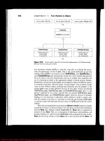
3.3
Decision
Making
Mechanism
in MAS
Figure
1
shows decision making mechanism
based
on
agents'
interaction.
Agents
engaged
in
cooperative
and
cordinative tasks usually have precise
information
about
the
other
agents'
goals
due to the
fact
that direct communication between
the
agents
is
possible.
Therefore
the
predictive model
is
usually deterministic.
In
case
of
competition,
the
agent
must
predict
the
other agents' goals based
on the
signals
from
the
opponents
rather than
direct
communication. Thus
the
predictive model
is
usually non-deterministic.
Figure
1.
Decision making mechanism
B.
Homayoun
Far /
Software
Agents
for
Uncertain
and
Complex Environments
33
4.
Uncertainty
in MAS
In
this section,
we
consider multi-agent interaction under competitive
and
uncertain
environments.
Information gained through
agents'
behaviour, i.e., signals
may be
incomplete.
Agents
in
competitive environments, must make decisions under uncertainty,
predict environment's parameters, predict other agents'
future
moves,
and
successfully
explain
self
and the
other agents' actions.
The
crucial factors
are
both
the
amount
and
specification
of the
information.
Any
lack
of
information
and/or noise
affects
the
quality
of
decisions,
the
moves
to be
performed
and
conclusion
to be
devised.
4.1
Overview
of
multi-agent competitive environment
Fig.
2
shows
the
outline
of
agent competition.
The
process
for
deciding competitive
strategy includes following steps. First, each agent tries
to
predict
opponents'
strategy.
Second,
the
agent
chooses
the
best
response
strategy based
on
previous predictions.
And
finally,
each
agent will
get a
payoff
by
using
a
utility
function.
Figure
2.
Overview
of
agents'
competition
From
the
decision making viewpoint, since
the
amount
of
payoff
in
extended games
is
influenced
by the
opponent's
moves, exact predictions
of the
other
agent's strategies
is
crucial
to
guarantee
a
stable
payoff.
Information about
opponents'
moves
is
uncertain
because they
may try to
hide their strategies
and the
knowledge behind
it as
much
as
possible.
The
work presented here suggests modeling
an
incomplete game theoretical based
decision
making method
for
competitive agents.
4.2
Modeling competitive environment
One
cannot exactly predict some agent's strategy because
of
lack
of
knowledge
on
opponent's preference since strategies
are
selected
based
upon each
agent's
preference
relations.
In
order
to
model such situation,
we
divide (opponent) agents into following
two
kinds:
•
Agents whose preference relations
are
exactly known.
•
Agents whose preference relations
are not
known.
34
B.
Homayoun
Far /
Software
Agents
for
Uncertain
and
Complex Environments
As
for first, we
treat them based
on
normal game theoretic approach.
As for
second,
we
regard these agents
as
natural objects
and
their strategies
as
state
of
nature
and
treat them
by
lumping
up all of the
natural objects
as
uncertainty. Following this principle,
we
define
a
multi-agent competitive environment
as:
Where
A is the set of
agents,
N is the set of
states
of
nature;
X is the
outcome
of
competition
and it is
defines
as: S
1
x
x
S
n
x N -> X ;
where,.
Si is the set of
strategies
of
agent
/; x is
the
preference relation
of
agent
i; and Pi, is the
information partition over
the
state
of
nature
of
agent
;. It is
represented
by
extensive
form
of a
game
as
shown
in
Fig.
3.
This
is a
simple
but
illustrative example
of
agents'
competition
model
(agent
I
versus
agent
2).
In
this example,
we
consider that agent
I
doesn't
know
the
preference relation
of
agent
2
and
thus, agent
I is
uncertain about which strategy agent
2
might
adopt.
Here,
PI is an
information
partition
of
agent
I and it is not
sure which
nodes
he
stays
in
(left,
right or
center)
within
P
1
.
Under
this
uncertain environment, agent
1
must
decide
which strategy
to
adopt
so as to
optimize
its
utility.
In
this case, agent
1
assigns
its
belief over
the
state
of
nature
and
adopts
the
strategy which maximizes
the
expected
utility.
If all the
agents decide
upon
strategy
in
this
way, there
is a
possibility
that
it
leads
to
social Bayesian perfect Nash
Equilibria
[10].
Figure
3.
Example
of
competition model
A
question which naturally arises here
is how
each agent
assigns
his
belief
autonomously.
The
answer
can be
achieved
by
dividing uncertainty into levels. Generally,
certainty
is
divided into three levels according
to the
amount
of
information about
the
state
of
nature
or
given signal
observed
before
choosing
among
several
strategies
[7].
•
Level-1: Decision making under certainty
The
agent knows exactly what
the
state
of
nature will
be. In
this
case,
decision
making
is
straightforward.
The
agent selects
the
strategy which maximizes
its
utility
using
traditional game theorey.
•
Level-2: Decision making under
risk
It
is
assumed that
the
agent
is not
sure what state
of
nature will
be, but it has a
probability
distribution over
the
state
of
nature.
In
this
case,
the
agent assigns
known probability distribution
as its
belief
and
selects
the
strategy which maximizes
expected
utility.
Below
we
propose
a
risk management method
in
order
to
reflect
each
agent's
attitude toward risk.
•
Level-3'. Decision making under uncertainty
In
this level,
we
assume
that
the
agent doesn't know anything about
the
state
of
nature
except
for
that
it is in
some set,
N =
iw.w, at\-
In
this case, agent
has to
B.
Homayoun
Far /
Software
Agents
for
Uncertain
and
Complex Environments
35
assign
his
belief without using probability distribution. Below
we
propose
a new
decision
making
and
belief assignment which reflects agent's degree
of
optimism.
*
It
should
be
noted that decision making under certainty (Level-1)
is a
special case
of
decision
making under risk (Level-2).
4.3
Decision making under risk
In
case
of
decision making under risk,
the
agent naturally
selects
a
strategy which
maximizes
its
expected utility. Generally, utility
function
is
decided
by
calculating
expected value
of
cost and/or benefit.
If
expected values
of two
strategies
are the
same,
these
two
strategies always become non-discriminateable. However,
one
cannot
say
that
this decision rule
is
rational. This
is
because, even
if the
expected values
are the
same,
when variance
is
large, risk
of
failure
increases.
Therefore,
it is
natural
to
consider that risk
of
failure
influences decision making. Therefore
in
order
to
make decisions under
the
risk,
we
must reflect each agent's attitude towards risk. Generally, attitude towards risk
is
categorized into
the
following three types [7].
•
Risk prone:
In
this
case,
agents
prefer
high risk-high return strategy rather than
low
risk-low return strategy.
•
Risk aversion:
In
this case, agents
prefer
low
risk
low
return strategy rather than
high
risk-high return strategy.
•
Risk neutral:
If
expected value
is the
same, these strategies always become non-
discriminateable.
In
the field of
economics, attitude toward risk
is
reflected
by
defining subjective probability
strictly.
But
this
is too
complicated
and
computationally expensive
to be
implemented
on
artificial
agents. Therefore,
we use
heuristic
function
that reflects
the
agent's attitude
towards
risk. The
utility
function
is
defined
by:
Where
* is a
pure
benefit
when agent adopt some strategy, E(x)
is a
expected value when
agent adopts some strategy, V(x)
is a
variance
and n. is a
coefficient
of
degree
of
risk
aversion taking values between
-1 and +1. If // is
plus,
the
function
u(x) becomes risk
aversion because,
the
larger variance
is
(means
the
larger risk
of
failure
is),
the
smaller
utility
becomes. Conversely,
if r\ is
minus,
function
u(x) represents risk prone because,
the
larger variance
is, the
larger
the
utility
becomes.
And if n is
zero, u(x) represents risk
neutral
because, u(x)
is
equal
to the
expected value when
the
agents
adopt
some strategy.
Using
this method, agents
are
allowed
to
select
a
strategy reflecting attitude toward risk
and
this simple representation
can be
easily implemented.
4.4
Decision making under uncertainty
In
case that
the
agent
has to
decide upon
the
strategy under uncertainty,
it has to
assign
its
belief without using
a
probability distribution. According
to
psychologists, when human
doesn't
know probability distribution over uncertainty (such
as
state
of
nature),
he/she
decides upon action
or
strategy based
on
degree
of
optimism. Here
we
quantify
each
agent's degree
of
optimism.
36 B.
Homayoun
Far /
Software
Agents
for
Uncertain
and
Complex Environments
In
order
to
quantify
degree
of
optimism,
we use
Ordered Weighted Averaging (OWA)
operator [13].
OWA
operator
of
dimension
n is
defined
as the
function
Fthat
has
associated
with
a
weighting vector
W.
such
that,
and and for any set of
some value
where
bj is the
largest element
in the
collection
Various semantics
can be
associated
with
the OWA
aggregation
procedure
in
this
framework
of
decision making under uncertainty, such
as
viewing
the OWA
weights
as a
pseudo-probability distribution [14].
In
particular
we can
view
as a
kind
of
probability
that
of the
best
thing happening.
In
this
case,
weights
(pseudo-probability)
are
assigned
not
to a
particular state
of
nature,
but to a
preference order
of the
utility. Thus,
is the
weight assigned
to the
best
utility
and w
n
is
assigned
to a
worst utility. Here,
a
question that
naturally
arises
is how the
agent
assigns
the
weights
it is
going
to use in
solving
some
problem.
At the
fundamental level,
the
answer
is
that
a
human expert interacting with
the
agent subjectively assigns
it. But
this
may be a
hard
job in
autonomous environments.
Thus,
we
propose
a
method
to
assign
the
weight
vector
automatically reflecting degree
of
optimism
of
agents. Using
OWA
operator,
the
degree
of
optimism
is
defined below [13].
Using this definition,
we
propose
the
method
to
assign
weight
vector
automatically.
Users
of
agents subjectively decide upon their degree
of
optimism
Opt(W).
They
then
input
this
value
into
a
following
linear programming
equation
max
-
Subject
to:
This approach
is
closely related
to the
maximum entropy method
used
in
probability
theory, which
is a
commonly used rationale
for
selecting
a
canonical probability
distribution
from
among
a set of
relevant ones.
Advantage
of
this method
is
that
for
various cardinalities
of
OWA,
we can
consistently
provide weights corresponding
to
given
Opt(W).
Using this method,
we can
treat decision
making
under uncertainty (problem
of
Level-3)
within
the
previously mentioned
framework
of
decision making under risk (problem
of
Level-2) since
we can
view
OWA
operator
as
pseudo-probability
distribution.
B.
Homayoun
Far /
Software
Agents
for
Uncertain
and
Complex
Environments
37
4.5
Analyzing opponents' moves
Using
decision making method mentioned above,
the
agent
can
decide upon optimal
strategy even under uncertainty. However,
in
order
to get a
stable
utility,
the
agent should
reduce uncertainty
by
analyzing opponents' moves
and
updating
its
belief.
A
method
for
belief update using dynamic
belief
network (DBN)
is
presented
in
[6].
5.
Conclusion
In
this paper,
we
addressed
the
complexity, knowledgeability
and
uncertainty issues
of
multi-
agent systems (MAS)
and
defined metrics
to
measure
the
complexity
of
MAS.
We
also
defined
knowledgeability
of MAS in
terms
of
problem
solving
and
cognitive
capabilities
and
the
ability
to
cope with agents' interactions. Finally,
we
devised models
and
techniques
to
cope with uncertainty
in
competitive situations.
References
[I]
Albrecht, A.J.
and
Gaffney,
J.F., Software Function, Source Lines
of
Code
and
Development
Effort
Prediction:
A
Software Science Validation, IEEE Trans. Software Engineering, vol.
9, no. 6, pp.
639-
648, 1983.
[2]
Boehm,
B.,
Software Risk Management, IEEE Computer Society Press,
CA,
1989.
[3]
Crosby, P.B., Quality
is
Free:
The Art of
Making Quality Certain, McGraw-Hill,
New
York, 1988.
[4]
Far, B.H.
et al, An
Integrated Reasoning
and
Learning Environment
for WWW
Based Software Agents
for
Electronic Commerce, Transactions
of
IEICE, vol. E81-D
no. 12, pp.
1374-1386, 1998.
[5]
Far, B.H., Agent-SE:
A
Methodology
for
Agent Oriented Software Engineering, Enabling Society with
Information
Technology,
Q. Jin et al.
eds.,
pp.
357–366, Springer, 2001.
[6]
Onjo,
H., and
Far, B.H.,
A
Unified
View
of
Heterogeneous Agents' Interaction, Transactions
of the
IEICE, vol. E84-D,
no. 8, pp.
945–956,
2001.
[7]
Ichikawa,
A.,
Decision Making Theory, Kouritsu Pub., 1983.
(in
Japanese).
[8]
Juran, J.M., Gryna, P.M. Jr., Bingham, P.M. (eds.), Quality Control Handbook (3
rd
edition), McGraw
Hill,
New
York, 1979.
[9]
Kan, S.H., Metrics
and
Models
in
Software Quality Engineering, Addison-Wesley, 1995.
[10]
Kajii,
A. and
Matsui,
A.,
Micro Economics:
A
Strategic Approach, Nihon-Hyouron Pub., 2000.
(in
Japanese).
[II]
McCabe, T.J.,
A
Complexity Measure, IEEE Transactions
on
Software Engineering, vol.
2, no. 4, pp.
308-320, 1976.
[12]
McCall, J.A., Richards, P.K., Walters, G.F., Factors
in
Software Quality, RADC TR-77-369, 1977. Vols
I,II,III,
US
Rome
Air
Development Center Reports NTIS AD/A-049 014, 015, 055, 1977.
[13] Yager, R.R.,
On
Ordered
Weighted Averaging Aggregation
Operators
in
Multi-Criteria
Decision
Making,
IEEE Trans. SMC,
no. 18, pp.
183-190, 1988.
[14]
Yager, R.R., Decision Making Under Dempster-Shafer Uncertainties, International Journals
of
General
Systems,
vol.
20, pp.
233-255, 1990.
38
Knowledge-based
Software
Engineering
T.
Welzeretal.
(Eds.)
1OS
Press,
2002
The
consistency management
of
scenarios
from
different
viewpoints
Atsushi Ohnishi, Zhang Hong Hui, Hiroshi Fujimoto
Department
of
Computer
Science,
Ritsumeikan
University
Shiga
525–8577, JAPAN
Abstract. Scenarios
that
describe concrete situations
of
software
operation
play
an
important role
in
software
development,
and in
particular
in
require-
ments
engineering. Scenario details should
vary
in
content
and
detail when
described
from
different
viewpoints
(e.g.
types
of
user
or
external
interface),
but
this presents
a
difficulty,
because
informal
scenarios cannot
easily
be
translated
from
one
viewpoint
to
another
with
consistency
and
assurance.
This
paper describes
(I) a
language
for
describing scenarios
in
which simple
action
traces
are
embellished
to
include
typed
frames
based
on a
simple case
grammar
of
actions
and for
describing
the
sequence among events,
and (2) a
transformation
method
of
scenarios
described
from
different
viewpoints
with
the
scenario
description
language.
I
Introduction
Scenarios
have important
uses
in
software specification
and
design
synthesis,
particularly
when used
to
gain insight into
the
implications
of
design
decisions
and for
customer
validation
and
acceptance.
However, scenarios
are
vague
and
imprecise tools
and are
therefore
difficult
to
integrate into more formal development
processes.
For
example, without defining what
it
means
for
actions
to be
included
in a
scenario,
it
is
impossible
to
compute differences among
scenarios
reliably.
(Is a
difference
because
of
an
unimportant omission,
or a
change
in
names,
or a
differently
instantiated variable,
or is
it
a
genuine inconsistency.)
Nor is it
possible
for the
scenarios
to
guide
the
refinement
of a
specification
other than
by
providing insight
to the
specifier. Detailed, instantiated
scenarios
of
the
kind used
for
customer validation
of
requirements
or the
generation
of
system test
cases
can't
be
generated
mechanically from
scenarios
described
just
in
text.
Most
importantly
vulnerabilities
of the
spec/scenario
system
are not
easily flagged. (E.g. what kinds
of
things
might
go
wrong
in the
performance
of
this action? What previously executed actions
does
this
scenario
or
scenario fragment
depend
on?)
We
claim that
scenarios
should
be
represented
in a
form that
is
closer
to the
application-
specific
concepts relevant
to
customer validation
and
system testing than
general-purpose
concepts such
as
"actor", "step", "event", "episode", "obstacle",
and
etc.
But
going
to the
extreme
of
application-specific representations relies
on
domain-specialists investing work
in
the
development
of
application-specific
(or
still
worse, system-specific) languages
and
tools.
An
intermediate, semantically rich,
but
application-neutral
set of
concepts
is
what's needed.
Extensions
to
scenario
and
action representations have been
proposed
before. Ohnishi's
requirements frame
model[7]
provides
a
vocabulary
of
general-purpose
action
and
information
types using structures
similar
to
those
of
case
grammar[3].
The
requirements frame model defines
the
case
structure
of a
concept.
For
example,
the
data
flow
(DFLOW) concept
has
agent, source, goal,
and
instrument
cases.
The
agent
case
A.
Ohnishi
et al. / The
Consistency
Management
of
Scenarios
39
corresponds
to
data that
are
transferred
from
the
source
case
object
to the
goal case object.
So, an
object assigned
to the
agent case should
be a
data type object.
An
object
in the
source
or
goal cases should
be
either
a
human
or a
function
type object.
If and
only
if a
human type
object
is
assigned
to
source
or
goal cases, some instrument should
be
specified
as a
device
case.
The
requirements
frame
enables
to
detect illegal usages
of
data
and
lack
of
cases[7].
Similarly, Potts
and
Anton
[2]
suggest that achievement-oriented goals
and
their occur-
rences
in
scenarios should
be
categorized into
a
number
of
basic types, (MAKE, KNOW,
etc.
) The
KAOS language formalizes some
of
these
differences
and
others
in
terms
of
action
pre-conditions
and
temporal-logic post-conditions.
In
other
areas
of
research,
there
are
numerous
proposals
for
specializing
action
types.
Case
grammar[3] suggests that
a
verb organizes
the
propositions conveyed
by
natural language,
the
concepts denoted
by
other parts
of
speech occupying well-defined cases.
Research
in AI has
sought
to
reduce action descriptions (for planning
and
understanding
applications) into semantic primitives [11]
and
their assembly into knowledge-rich memory
structures
and
cases.
Speech-act theory[12] proposes
a
number
of
basic communicative actions that have dif-
ferent
assumptions
and
consequences
in
human communication. Speech-act theory
is an
area
of
continuing interest
in
linguistic pragmatics. Speech-act theory
was first
proposed
as a
framework
for IS
analysis
by
Lyttinen [5],
and has
also been applied
in
CSCW[6]. Thus,
rather than sending each other generic messages, users
of a
speech act-based CSCW system
promise,
request,
refuse, etc.
In the
ESPRIT CREW project, goal modeling
and
scenario
authoring
approach
is
proposed[10].
In
this paper,
we
outline
a
frame-based approach
for
structuring
the
actions
in a
scenario.
We
use
ideas
from
previous work[7]
and
Jackson's problem frames
[4] for
structuring
the
content
of
scenarios
and
action descriptions
in
specifications. Thus, there
are
different
case
frames
for
different
problem
frames,
but far
fewer
case
frames
than there
are
systems
or
problem domains.
2
Scenario Description Language
Scenarios
can be
regarded
as a
sequence
of
events. Each
of
events
has a
certain action.
We
have developed
a
scenario description language based
on
this concept.
2.
/
Event description
Each
of
events
has
just
one
verb,
and
each
of
verbs
has its own
case
structure. Verbs
and
their
own
case
structures
are
depend
on
problem
domains,
but
roles
of
cases
are
independent
of
problem domains. There exist several roles, such
as
agent, object, recipient, instrument,
source,
and so on.
An
entity doesn't have
one of
these
as a
type,
but
plays these
as
roles. (Thus
a
person
may
be a
user
with
respect
to
requesting services
of the
system,
but a
consumer
of its
outputs.
)
There
are
some constraints. Thus,
we
expect entities either
to be
users
or
phenomena,
but not
both with respect
to
different
actions.
We
provide action
frames
as
shown
in
Table
1.
Just
like Ohnishi's Case Frame[7], each
of
actions
has its
case structure.
For
example,
action
"move"
has
four
cases, such that
"agent,
"
"source,
"
"goal,
" and
"instrument.
" A
sentence "Mr.
X
moves
from
Tokyo
to
Slovenia
by
airplane"
can be
transformed
into
an
internal
representation
as
shown
in
Table
2.
We
assume that
a
scenario
represents
a
sequence
of
events,
and
each
of
events
can be
trans-
formed
into
internal
representation based
on the
above action
frame.
Just
like
Requirements
A.
Ohnishi
et al. / The
Consistency
Management
of
Scenarios
Table
1:
Action
frames
cases
TransTorm/derive/compute
Collate/compare
Report
on/
monitor/sense
Query/ask/recruit/appoint
Command/control
Suggest/request
Create/make/edit/arrange/decide
Feedback
Notify/send/receive/distribute/move
Allocate/
schedule/seize/assign
Cancel/
relinquish
Exist/locate
React
agent,
source, goal, object
agent,
source, object
agent,
source, operation, instrument
agent, object, goal
agent,
recipient, operation,
instrument
agent,
object, goal
agent,
source, goal
agent,
recipient,
operation, instrument
agent,
object, source, goal,
instrument
agent, object, goal
agent,
recipient, operation,
instrument
agent,
status
agent,
operation,
instrument
Table
2:
Internal
representation example
;
Action
move
agent
Mr.
X
source
Tokyo
goal
Slovenia
instrument
i
airplane
Frame,
we can
detect both lack
of
cases
and
illegal usages
of
noun type[7].
2.
2
Sequence
description
As
previously
described,
scenarios
define
a
sequence
of
events.
We
assume
seven
kinds
of
time
sequences,
such
as 1)
sequence,
2)
selection,
3)
iteration.
4)
AND-fork,
5)
OR-fork,
6)
exclusive
OR-fork,
7)
AND/OR/XOR-join.
Since most events occur sequentially,
the
sequence
of
sequential events
need
not be
apparently
described.
In
other words,
ordered
events
can be
regarded
as
sequential events.
For
example,
the
following
ordered
three events occur sequentially.
1.
A PC
chair decides
a
schedule.
2.
He
sends
the
schedule
to a
publishing company.
3.
He
arranges keynote speakers.
To
specify
selective
events,
we
provide
"if
then else
"
syntax
just
like
most
of
program
languages.
For
example,
if
an
author
has his own
addresses, then
he
sends
a
notification letter
to
the
author
via
else
he
sends
a
notification letter
to the
author
via
postal
mail.
To
specify iterative events,
we
provide "Do until
"
syntax just like most
of
program
languages.
For
example,
in
case
of
late reviewing,
Do he
urges
a
review report
to a
reviewer until
the
reviewer
sends
a
report.
To
specify parallel
events,
we
provide
"AND-fork
AND-join, OR-fork OR-join,
" and
"XOR-fork
XOR-join.
" An
example
is
shown below.
40
A.
Ohnishi
et al. / The
Consistency Management
of
Scenarios
41
AND-fork
a)
he
distributes
CFP to
related societies
and
organizations.
b)
he
sends e-mails
to
members
of
the
related societies
AND-join
Since
our
scenario description language enables
to
define both
the
syntax
and the
semantics
of
scenarios,
we can
analyze
and
validate
scenarios
written with this
language.
3
Scenario Example: Program chair's
job
We
consider
a
scenario
of
program chair's
job at an
international conference. This scenario
is
based
on a
problem provided
by
Requirements Engineering Working Group
(RE
WG),
Information
Processing Society, Japan. Similar
job
description
is
provided
by
ACM[1].
3.
1
Scenario from
PC
chair's viewpoint
The
followings
are
program chair's jobs written
with
our
scenario description language.
1.
A PC
chair decides
a
schedule
(of
the
paper submission deadline,
program
committee
s
meeting, acceptance/rejection
notification,
camera
ready
paper due).
2. He
sends
the
schedule
to a
publishing company.
3.
He
arranges keynote speakers.
4.
He
makes
Call
for
Paper.
5.
AND-fork
a)
He
distributes
it to
related societies
and
organizations.
b)
he
sends e-mails
to
members
of
the
societies.
AND-join
6.
He
recruits program committee members.
7.
He
makes
a
list
of
members (including member's name, address,
affiliation,
phone
number,
FAX
number, e-mail address,
and
research area).
8. He
assigns paper
IDs to
submitted papers.
9.
Each
of
submitted papers
has
title, author name, address,
affiliation,
phone
number,
e-mail address,
FAX
number, abstract,
and key
words.
10.
if
an
author
has his own
e-mail addresses, then
PC
chair sends
an
acceptance mail
to
the
author
via
else
he
sends
an
acceptance mail
to the
author
via
postal
mail.
11.
He
sends
a
list
of
papers
to all the PC
members.
12.
PC
members select their candidates
of
papers.
13.
PC
members send their candidates
of
papers
for
reviews
to the PC
chair.
14.
PC
chair makes
a final
assignment
of
reviewers.
15.
He
sends reviewer's sheets
and
submitted papers
for
review
to PC
members.
16.
He
receives reviewer
s
results
42
A.
Ohnishi
et al. / The
Consistency
Management
of
Scenarios
17
The
events
of the
above scenario
can be
transformed into internal representation below.
In
the
transformation, concrete words
will
be
assigned
into pronouns
and
omitted indispensable
cases. Some
cases
are not
indispensable,
but
optional.
In
case
of
optional
cases,
such
as the
instrument
case
of
action "inform,
" a
concrete word
may not be
assigned.
The 9th
event
of
the
above scenario
is not
transformed, because data structure cannot
be
internally represented.
3.
2
Scenario
from
PC
member's viewpoint
In
this subsection,
we
will
describe
how to
derive
a
scenario
of the
same
job
description
of
PC
member's viewpoint
from
the
scenario
of PC
chair's viewpoint.
First,
we
derive events
including
PC
members
or
reviewers.
1.
He
recruits program committee members.
2.
He
sends
a
list
of
papers
to all the PC
members.
3.
PC
members send their candidates
of
papers
for
reviews.
4.
PC
chair makes
a final
assignment
of
reviewers.
5.
He
sends reviewer's sheets
and
6.
He
receives reviewer's results
Actually,
the
internal
representation
is
independent
of
viewpoints.
For
example,
in
case
of
action
"send,
receive,
inform,
and so on, " the
action frame
can be
represented
as
"source
case
object" sends
"object
case object"
to
"goal
case
object"
with "instrument
case
object.
" The
viewpoint
of
this representation becomes source case object.
The
action frame
can be
also
represented
as
"goal
case object" receive "object
case
object"
from
"source
case
object"
with
"instrument
case
object.
" The
viewpoint
of the
second representation
becomes
the
goal
case object.
The
action frame
can be
also represented
as
"object
case
object"
is
sent
from
"source
case object"
to
"goal
case object"
with
"instrument case object.
" The
viewpoint
of
the
third
representation becomes
the
object case object.
In
case
of the
last event
of the
above example,
this
event
can be
represented
as
• PC
members send reviewer's results
to PC
chair.
• PC
chair receives reviewer's results
from
PC
members.
•
reviewer's results
are
sent
from
PC
members
to PC
chair.
from
the
action
frame,
we can get a
scenario
from
PC
members
as
below.
1.
PC
members
are
recruited
by PC
chair.
2.
All the PC
members receive
a
list
of
papers
from
PC
chair.
3.
PC
members send their candidates
of
papers
for
reviews
to PC
chair.
4.
Reviewers
are
assigned
by PC
chair.
5.
PC
members
receive
reviewer's sheets
and
from
PC
chair.
6.
PC
members send reviewer's results
to PC
chair.
By
checking
the
derived scenario
by PC
members, both lack
of
events
and
wrong sequences
of
events
can be
easily detected.
In
this
case,
the
lack
of an
event that reviewer should receive
reviewers' guideline
from
PC
chair
is
detected.
If
another scenario
of an
exceptional
handling
is
specified
from
PC
chair's viewpoint,
we
can get a
scenario
of the
same
exceptional
handling
from
PC
members'
viewpoint.
A.
Ohnishi
et al. / The
Consistency
Management
of
Scenarios
43
4
Conclusions
We
have developed
an
action frame base scenario description language
and
transformation
rules between scenarios from
different
viewpoints. With
these
rules,
we can get a new
scenario from
PC
members'
viewpoint
by
transforming
a
scenario
from
PC
chair's
viewpoint.
Through
our
example,
we
found
the
scenario transformation with action frame enables
to
improve several quality
of
scenario.
1.
System developer
does
not
need
to
describe scenarios from several different viewpoints.
If
he
specifies
a
scenario from
one
viewpoint, then
he can get a
scenario from another
viewpoint
with transformation rules. This contributes
to
improve
the
productivity
of
scenarios.
2.
If
system developer specifies
two
scenarios
from
different viewpoints,
he can
check
the
lack
of
events
and
check
the
consistency
of
scenarios
by
comparing
a
scenario
with
a
transformed
scenario that
is
created
by
transforming
other
scenario. This contributes
to
improve
the
completeness
and the
consistency
of
scenarios.
We
have been researching
an
integration method
of
scenarios described from different
viewpoints[9]
and
developing
a
prototype system based
on our
methods.
We
have
to
validate
the
ideas
more
thoroughly
by
applying
to
several
different
problem
domains
and
have
to
estimate
our
methods with
the
prototype system.
References
[I]
"ACM Conference Committee
job
description,
"
Conference Manual, Section
6. 1. 1,
http:
//www.
acm.
org/sig-Volunteer.
info/conference.
manual/6-l-lPC. HTM.
[2]
Anton,
A. I. and
Potts,
C.:
"The
use of
goals
to
surface requirements
for
evolving systems,
"
Proc.
20th ICSE,
pp.
157–166, IEEE Comput. Soc, 1998.
[3]
Fillmore,
C. J.:
"The Case
for
Case,
" in
Bach
and
Harms (Eds.
),
"Universals
in
Linguistic
Theory,
"
[4]
Jackson,
M.:
"Problems
and
requirement,
"
Proc.
2nd
ISRE,
pp.
2-8, IEEE Comput. Soc., 1995.
[5]
Lyttinen,
K. J.:
"Implications
of
theories
of
language
for
information systems,
"
Manage. Inf.
Syst.
Q.,
vol.
9, no. 1, pp.
61–74, 1985.
[6]
Medina-Mora,
R.,
Winograd,
T,
Flores,
R.,
Flores,
F.: " The
Action Workflow approach
to
workflow
management technology,
"
Proc. CSCW '92,
pp.
281–288,
1992.
[7]
Ohnishi,
A.:
"Software Requirements Specification Database Based
on
Requirements Frame
Model,
"
Proc.
of the
IEEE second International Conference
on
Requirements Engineering
(ICRE'96),
1996,
pp.
221–228.
[8]
Ohnishi,
A.,
Potts,
C.:
"Grounding Scenarios
in
Frame-Based Action Semantics,
"
Proc. REFSQ
01,
pp.
l77-182, 2001.
[9]
Ohnishi,
A.,
Zhang,
H.
H.,
Fujimoto,
H.: "
Transformation
and
Integration Method
of
Scenarios,
"
Proc.
COMPSAC 2002, 2002.
[10] Rolland,
C.,
Souveyet,
C., and
Achour
C. B.:
"Guiding Goal Modeling Using Scenarios,
"
IEEE
Trans.
Softw,
Engnr.,
Vol.
24, No. 12, pp.
1055–1071, 1998.
[11] Schank,
R.:
"Representation
and
Understanding
of
Text,
"
Machine Intelligence
8,
Ellis Hor-
wood Ltd., Cambridge,
pp.
575-607, 1977.
[12]
Searle,
J. R.: "An
Essay
in the
Philosophy
of
Language,
"
Cambridge Univ,
Press,
1969.
44
Knowledge-based
Software
Engineering
T.
Welzerelal.
iEds.
)
IOS
Press,
2002
A
Controlling
System
of
Progress
for
Users
by
Using
Use
Cases
Kyoko
YOSHIDA
Faculty
of
Law,
Heisei International University
2000
Mizufukaohtateno
Kazo, Saitama, 347-8504. Japan
e-mail:
yoshida-shirao@,
eva.
hi-ho.
ne.
jp
MorioNAGATA
Dept.
of
Administration Engineering,
Faculty
of
Science
and
Technology
Keio University
3–14–1 Hiyoshi, Yokohama, 223-8522, Japan
e-mail:
nagata@ae. keio.
ac.
jp
Abstract. Controlling
the
progress
for
software development project
has
been
man-
aged
from
only developers' point
of
view. Especially
in
implementation
phase,
the
progress
reports
of
coding
and
testing have been explained
by
using modules
or
classes. However,
it is not
easy
for
users
to
understand those specified notions.
In
object-oriented methods,
it is
advocated
to
keep
the
consistency
of the
process
by-
using
use
cases,
which
are
understandable
for
users
and
developers.
Nevertheless,
in
the
present
stage,
use
cases
have
not
been
used
enough
to
improve
the
communica-
tion
between
developers
and
users.
We
propose
a new
controlling system
of
progress
by
using
use
cases
in
implementation
phase,
which
doesn't
increase
developers'
bur-
dens.
This system
was
accomplished
by
linking
classes
and
methods
in
both
of im-
plementation
phase
and
analysis phase.
Introduction
Project management
of
software development
is
known
by its
failure
rather than
success.
Few
projects
in
Japan
can
keep
the
conditions
on
their
cost,
schedule,
or aim of the
projects
that
are
planed
at the
start
of
development. Even
in U. S. A., it is
said that
one
third
or two
third
of
software projects overrun
the
schedule
and the
cost,
too
[1].
When
the
project
falls
behind
the
schedule
on the way of
development,
its
cost
and
schedule
are
re-estimated,
but
they don't work
as
expectedly
in
many
cases.
A lot of
projects
spend
more money
and
manpower
than
expected.
In
many
cases,
these
developments
have
a
tight
schedule
from
the
beginning.
The
schedule
is
determined
by
customers, users
or
software companies.
But,
there
are
several
different
understandings
on the
term
for
software development
between
stakeholders
and
developers. Usually such misunderstandings
are not
clear
at the
starting point
of
develop-
ment.
Many schedules
are
determined shorter
than
developers' expectation,
but
they don't
K.
Yoshida
and M.
Nagata/
A
Controlling
System
of
Progress
for
Users
45
think
it
seriously.
After
the
start
of
software
development, developers have
to
concentrate
on
problems should
be
solved
at
each step.
On the
other hand,
the
customers
who
order
software
development (users
are
considered
as
customers here) cannot know exactly
how
the
development
is
going. Therefore,
it
becomes more
difficult
to
understand
and to
com-
municate
on the
present condition
of the
software development each other,
and it
exerts
a
bad
influence
upon
the
development.
1.
Problems
on
software developments
and our
proposal
On
software development, there
is a
problem that users cannot catch
the
situation
of de-
velopment.
Usually,
process
management
has
been
done
from
developers'
point
of
view
and
users'
viewpoint
is
neglected.
In
actually, developers have
the
initiative
of
process con-
trol, especially
after
design phase started. Developers explain
for
users about
a
situation
of
process, using classes
in
object-oriented methods
or
modules
in
structural methods.
Unfor-
tunately,
users know hardly
how the
actual development
is
going. Therefore,
we
need
the
system
that user
can
understand easily
the
situation
of
progress
on the
development.
In
many cases, where software development
falls
behind
the
schedule, developers
and
users
are not
able
to
communicate each other well. Then,
the
project managers increase
numbers
and
working hours
of
engineers
who
engage
in the
development.
But the
manager
doesn't have enough time
to
explain
the
situation
to
users,
and it is
usually
left
on the
back
burner.
In
this case,
it
happens
often
to
change
the
order
of
programming,
and
developers
and
users should communicate each other
at
this step. Thus,
we
need
the
system that helps
the
smooth negotiation.
Meanwhile,
in the
Unified
Software Development Process
by
UML, iterative
and in-
cremental
developments
are
advocated [2]. These developments
are
more complex
on
progress
control than development
of
waterfall
methods. Especially
in the way of
iterative develop-
ment,
once
software
development delayed,
it is
difficult
to
measure
the
influences
of the
delay
for
subsequent works. Then
a
high priority tasks
or a
hidden
risk
might
be
forgotten.
The
dangers
of
these misses
are
bigger
in
iterative
and
incremental developments than
the
cases
of
waterfall
methods
and the
controlling progress becomes more important
in the
former
one [3, 4].
With
paying attentions such points,
this
paper proposes
a
controlling system
of
progress that both users
and
developers
can use
easily. This system,
we
tried
to use use
cases
for
controlling progress
of
software
development
from
analysis
to
test phase.
Usually,
users
and
developers
specify
the
function
of
system
by
using
use
cases (scenario).
After
design phase
started,
developers
use the
unit
of
classes
or
methods, which
are not
usually understandable
by
users.
But
users
can
understand
use
cases.
Therefore,
to
bridge
the gap
between users
and
developers,
we
have
to first
connect
use
cases with classes
and
methods
in
design phase,
and
then translate
classes
and
methods into
use
cases
in
implemental phase,
and
indicate them
to
users. This
system
also helps
the
communications between users
and
developers without increasing
developers'
burdens.
46 K.
Yoshida
and M.
Nagata
/ A
Controlling
System
of
Progress
for
Users
2.
Our
system
2.
/
Assumption
Let
us
consider
a
software
development
of
object-oriented methods.
We
apply
the
system which
will
be
obtained
in
2.
2 to
implementation phase
and
testing phase. These phases cause
the
delay
of
devel-
opment
and
cost
up of the
development
often.
This
time, we
treat only
the
process
of
implementation
and
test phase
in its first
cycle,
and
don't consider
the
influence
on the
iterative
and
incremental
de-
velopment.
As the
scale
of
software
development
we
take
one
which will
be
made
within
a few
months
by
several people.
In
this system
we use the
form
of use
cases
proposed
by
Craig Larman (Figure
1). The top
part
of
this
use
case
is
summary information.
The
main part
is
'Typical
Course
of
Events" which
de-
scribes events methodically.
The first
sentence
of
description states
the
preconditions
of
this
use
case.
Next,
"actor action"
and
"system
response"
is
explained
with
numbering.
It
describes
in
detail
the
conversation
of
interaction
between actors
and a
system,
and it is the
most common
or
typical story
of
events.
In
"Ahemative Course
of
Events",
the
alternatives
or
exceptions
of
events
are
described
And
then,
actors
are
defined
in the
part
of
actor
in the use
case [5].
Use
case:
Actors:
Purpose:
Overview-
Type:
Cross
References:
Name
of
use
case
List
of
actors (external agents), indicating
who
initiates
(he use
case
Intention
of
the
use
case.
Repetition
of
the
high-level
use
case,
or
some similar summary
primary,
secondary
or
optional
essential
or real
Related
use
cases
and
system functions.
Ty
Actor Action
Numbered
actions
of
the
actors.
Alternative
Course
of
Events
line
number Description
of
exception
System Response
Numbered
descriptions
of
the
system
responses
Figure
1. The use
case
form
by
Craig Larman
2. 2
Flow
of
the
system
The
system goes
as
follows.
(1)
Users
and
developers make
use
cases
(2)
System generates automatically
the
sequence diagrams
from
the use
cases.
(3)
By
using
the
sequence diagrams, users
and
developers
can
change
the
names
or the
places
of
classes
and
messages made
of
sentences
in the use
cases.
(4)
System generates
classes
and
methods
for
analysis process.
(5)
Developers convert classes
or
methods into implementation process.
(6)
Developers
input
an
estimated manpower
for
each method
K.
Yoshida
and M.
Nagata/
A
Controlling
System
of
Progress
for
Users
47
(7)
Developers
input
the
degree
of
progress
for
each method
(8)
System presents
the
progress reports
for
users
by
using
use
cases
and one
for
developers
by
using
classes
or
methods
Use
cases
in (1)
should
be
described
by
simple sentence according
to
their abstraction levels.
(2)
will
be
stated
in
Section
2. 3. On the
basis
of the
sequence diagram
in
(2), developers
and
users
analyze
the use
cases,
and
connect
the two
objects
and the
message. These objects will
be
classes,
which
we
call
the
object here
to
avoid confusion.
The
corresponding message between them
is
con-
nected into
one
sentence
of the use
cases.
In
(4),
classes
and
methods
for
analysis process
are
auto-
matically generated.
In (5)
developers convert these objects
for
implementation
process,
considering
the
computer architecture
and
coding.
(4) and (5)
will
be
shown
in
Section
2.
4.
After
designing
of im-
plementation
classes,
developers
can
input
an
estimated manpower
for
each method
in
(6).
In
(7), they
input
also
the
degree
of
progress
of
coding
and
testing
for
each method
at
every
fixed
period.
As the
degree
of
progress, they
use
usually rough percentages (for example, 30%, 70%, 90%, 100%). Some-
times only
two
data
0% or
100%
are
used
to
make clear
the
finished
or not of a
task. This
time, we use
2
data
0% or
100%.
In
(8),
the
system completes
the
progress reports
for
users
and
developers.
2. 3
Analysis
of
use
cases
We
use the
Japanese morphological system called Chasen[6]
as a
preprocessor
of our
system. Using
the
output
of
Chasen,
we
arrange
the
analyzed sentences
of
"actor action"
and
"system
response"
ac-
cording
to the
order
of the
events.
The
sentences have
a
certain
form.
In
"Actor Action",
the
subject
is
always
actor,
and
"action
to
system"
and
"action
to
another actor"
are
described
In
"System
Re-
sponse",
the
subject
is
always system,
and
"action
to
another system
process"
and
"action
to
actor"
are
also described. Thus,
it is
possible
by
using particles
the
sentences
in
'Typical
Orders
of
the
Events"
to
classify
into
the
patterns
of
Figure
2,
which
is
stated
in
Japanese.
Sequence
diagram
Figure
2.
Patterns
of
sentence
in
'Typical Course
of
Events"
For
the
sentences which
are not
classified above,
we
avoid them
from our
system
as
mean-
ingless sentences. When these sentences
are
needed
later,
then
we can add
them
to the
sequence dia-
gram.
Thus each sentence corresponds
to
objects
and a
message each other. Then users
and
develop-
ers
check these objects
and
message
in the
sequence diagram
and
change them
if
they
are not
suitable.