PROGRAMMING AND CUSTOMIZING THE PIC MICROCONTROLLER 3rd phần 2 potx
Bạn đang xem bản rút gọn của tài liệu. Xem và tải ngay bản đầy đủ của tài liệu tại đây (2.74 MB, 130 trang )
MICROCHIP MPLAB IDE 103
probably make every day with respect to selecting which source code files are to be used
in a new version of your application—or trying to go back to a previous version of the
code, only to find that it was overwritten—will become a thing of the past. MPLAB helps
facilitate version control through its use of projects. Later in this chapter I will spend
some time explaining how to set up projects in MPLAB and how they can simplify your
application development as well as ensure that you are only working with the code spe-
cific to the current version of the application.
Microchip MPLAB IDE
Although there are a number of companies that have created IDEs and development tools
for the PIC microcontroller, I believe that Microchip’s MPLAB IDE is the best, both
for beginners as well as experienced developers. MPLAB IDE offers the basic devel-
opment functions, including an editor, assembler/linker/builder interface, and a simu-
lator, but it also includes more advanced features such as programmer, emulator and
debugger interfaces that eliminate the need for learning new tools. MPLAB IDE also
provides the facilities for cross-referencing machine code and hard addresses back to
the source files to allow the editor to indicate the current line or update the data watch
windows. The software is professionally written and you will probably not experience
any problems with it, which will make the process of learning the tool and how to
develop applications for the PIC microcontroller more efficient. MPLAB is fairly unique
because Microchip provides this tool free of charge to download off the web. Not having
this type of development tool would make learning the PIC microcontroller much more
difficult.
MPLAB IDE is a very complete integrated development environment for all the PIC
microcontroller families and runs under Microsoft’s Windows operating system. The tool
is regularly updated, so you should check Microchip’s web site periodically to see if
new versions of the tool are available for download and if there are new chip support,
features, or bug fixes that you will require. Along with this tool, Microchip provides a
set of forums where you can post questions or help others learn about PIC MCU appli-
cations or MPLAB IDE operation. Microchip, like many other vendors, has embraced
the Internet and provides software and datasheets on their web site, which you can
access to help you develop your PIC microcontroller applications.
INSTALLING MPLAB IDE
In the previous editions of this book, I included a diskette or CD-ROM with copies of
the Microchip development tools (the first edition included MS-DOS command-line tools
while the second edition included a copy of the Windows version). The problem with
doing this is how quickly the copies became out of date; Microchip continually updates
MPLAB IDE with new features and new chip support, which is why I recommend that
you download the code from the web and install it directly on your PC. In this section,
I will guide you through the process of installing MPLAB IDE, followed by showing
Simpo PDF Merge and Split Unregistered Version -
104 SOFTWARE DEVELOPMENT TOOLS
you the process of creating a project and installing an introductory C compiler that will
give you quite a bit of flexibility in creating your own applications.
Before starting the installation process, there are a few things for you to do to ensure
a trouble-free installation. First, you must be prepared to spend an hour for the
installation—the process is definitely not “fire and forget,” and you will have to be
present throughout the download and installation. The installation requires a lot of your
PC’s resources, so all other applications, except for folder windows and an Internet
browser, should be closed before you start downloading and definitely must be closed
when you start the installation process. Finally, some antivirus tools may attempt to block
the download; if necessary you should temporarily enable this capability if it is disabled.
Downloading and installing MPLAB IDE is a significant operation and one that you
should be prepared for to ensure that it goes smoothly.
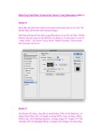
The first step is to go to the Microchip web site (Fig. 3.10) and click on MPLAB®
IDE in the Design box. This will bring you to a new page devoted to the MPLAB IDE
from which you can review the features of the software and download the application
Figure 3.10 Microchip’s web site can be found at www.microchip.com.
Simpo PDF Merge and Split Unregistered Version -
MICROCHIP MPLAB IDE 105
or datasheets. Scroll down to the bottom of the page (shown in Fig. 3.11) and click
on the appropriate Download option. I usually select the Full Zipped Installation
rather than the Interim Release to ensure that the software and its features are fully
tested.
When you are given the option of where to put the .zip file, select a temporary folder
such as C:\temp. Once the program has downloaded (depending on your Internet con-
nection, this can range from five minutes to over an hour; at the time this was written,
the full MPLAB IDE package is greater than 30 megabytes), run an unzip program, and
store (extract) the contents into the C:\temp folder. Figure 3.12 shows the .zip file with
the extracted contents; the application installation files ready to load MPLAB IDE onto
your PC.
With the full .zip program downloaded and the MPLAB IDE setup files extracted from
it, double-click on MPLAB IDE v#.## Install (where “#.##” is the version number of
Figure 3.11 Click on Download Full Zipped Installation to get the most recent fully tested
release of MPLAB IDE.
Simpo PDF Merge and Split Unregistered Version -
106 SOFTWARE DEVELOPMENT TOOLS
MPLAB IDE) and follow the instructions to install the program onto your PC (Fig. 3.13).
Before the installation completes, you should have the opportunity to display the readme
files for the different functions. I recommend that you do so, to help familiarize your-
self with the program and its capabilities.
When the installation is complete, you can delete the contents of the C:\temp folder.
MPLAB IDE is constantly updated and improved. As I noted at the start of this section,
I didn’t feel that it would be helpful to provide you with a copy of the tool on a CD-
ROM and I do not believe there is a reason for you to save a copy either—if you have
a disk crash or want to migrate to a new PC, you should download a new copy of
MPLAB IDE and install it (using the procedures outlined in this section). Similarly, every
couple of months or so, you may want to check to see if there is a new version of the
program available for download. If there is, you will want to install it to take advantage
of the latest changes. You do not have to remove the current copy of MPLAB IDE, the
installation program will do that for you. There really is no reason to save the installa-
tion file that you have downloaded and unzipped.
Figure 3.12 Extract the MPLAB IDE installation files from the downloaded .zip file and
store in a temporary folder.
Simpo PDF Merge and Split Unregistered Version -
MICROCHIP MPLAB IDE 107
Now you should have a desktop icon which you can click to start up MPLAB IDE.
The first time you click on the icon, don’t be surprised if it takes up to five minutes
for the program to configure itself and do final setups before you can use it. Later
program invocations will be much faster. Once the MPLAB IDE desktop is up and
running (Fig. 3.14) you are able to create your first application.
MPLAB IDE FILE TYPES
While MPLAB IDE does a lot to shield you from the various files that are required and
produced when you are creating an application, you should be aware of the different
files involved in the creation of an application. When you are creating an application,
along with the source code you should be aware of the need for include files as well as
linker control files. When assembly or compilation is complete, the process will pro-
duce a number of files which, along with the .hex file (which is programmed into a PIC
microcontroller) are resources for the linker and the debugger or emulator tools. You
Figure 3.13 After unzipping the MPLAB File, click on MPLAB IDE v#.## Install and follow
the instructions to install MPLAB IDE for a complete installation.
Simpo PDF Merge and Split Unregistered Version -
108 SOFTWARE DEVELOPMENT TOOLS
do not need to concern yourself with the various MPLAB IDE project management files
(such as the files that end in .mcp, .mcs, .mcw, etc.) because these files will change with
different versions of MPLAB IDE as well as the project and the tools used to build the
application. I realize that when you are starting out with a new device, the number of
things to learn is overwhelming; the purpose of reviewing the file types is to help you
understand the process and choose the path that will allow you to most efficiently learn
how to program the PIC microcontroller.
In Fig. 3.15, I have drawn the build process as a large box encompassing the assembler/
compiler and the linker process step as well as showing the files required and produced for
the two process steps. For your first application, you should be aware of the process and
the purpose of the ten file types shown here. As you become more familiar with the PIC
microcontroller, MPLAB IDE and the development tools, you will be able to customize
these files to make your application development more sophisticated.
The need for the source files should be self-explanatory—the .asm, .bas, and .c files
that are created as the program is run through the assembler/compiler are entered into
Figure 3.14 Finished installing MPLAB IDE—the desktop is up and running.
Simpo PDF Merge and Split Unregistered Version -
the MPLAB IDE editor and then passed through the build process. Later in the book, I
will comment on how these files should be written and give basic templates for your
use, but for now, I want to identify them as files that are the basis of the application.
Often, one of the first things I see when new PIC microcontroller programmers have
problems with their initial applications is that they have defined the hardware regis-
ters they are going to use in their applications. The programmer is mystified why the
code doesn’t work or, in some cases, assemble correctly. Almost invariably, the prob-
lems with the application are a result of a typo or transposition of a register address
or label. To fix the problems, I will tell them to delete the hardware register declara-
tions in their source code and use the include directive to load the Microchip or
compiler vendor written .inc register definition files into their applications. These
files were written to provide the application developer with the addresses of the PIC
microcontroller hardware registers, along with some other parameters, in the same
format as the documentation. Usually, when the programmer-defined hardware reg-
ister declarations are deleted and the .inc file added to the source, the application prob-
lems disappear.
When working with the MPASM assembler, there is an .inc file for every PIC micro-
controller part number in the format:
p<I>PIC_MCU_P/N</I>.inc
where <I>PIC_MCU_P/N</I> is the PIC microcontroller part number. For example,
the include file for the PIC16F84A is p16f84a.inc and the include file for the PIC12C508
is p12c508.inc. This is true for all the PIC microcontroller devices except for the origi-
nal, low-end (PIC16C5x) parts. For these devices, the include file is p16c5x.inc.
The file below is p12c508.inc, which is relatively small, but has all the elements that
you should look for in the include files.
MICROCHIP MPLAB IDE 109
Assembler/
Compiler
Linker
.asm/.c (Source) Files .inc (Include) Files
.lib (Library) Files
.hex File .cod/.cof Files
.o (Object) Files
.o (Object) Files
.lkr (Linker) Files
.lst (Listing) Files
.map File
.err (Error) Files
Figure 3.15 The application build process requires
and produces the various files shown here.
Simpo PDF Merge and Split Unregistered Version -
110 SOFTWARE DEVELOPMENT TOOLS
LIST
; P12C508.INC Standard Header File, Version 1.02 Microchip
Technology, Inc.
NOLIST
; This header file defines configurations, registers, and other useful bits
of
; information for the PIC12C508 microcontroller. These names are taken
to match
; the data sheets as closely as possible.
; Note that the processor must be selected before this file is
; included. The processor may be selected the following ways:
; 1. Command line switch:
; C:\ MPASM MYFILE.ASM /P12C508
; 2. LIST directive in the source file
; LIST P=12C508
; 3. Processor Type entry in the MPASM full-screen interface
;===============================================================
;
; Revision History
;
;==============================================================
;Rev: Date: Reason:
;1.02 05/12/97 Correct STATUS and OPTION register bits
;1.01 08/21/96 Removed VCLMP fuse, corrected oscillators
;1.00 04/10/96 Initial Release
;==============================================================
;
; Verify Processor
;
;==============================================================
IFNDEF __12C508
MESSG “Processor-header file mismatch. Verify selected
processor.”
ENDIF
;===============================================================
;
; Register Definitions
;
;===============================================================
Simpo PDF Merge and Split Unregistered Version -
MICROCHIP MPLAB IDE 111
W EQU H’0000’
F EQU H’0001’
; Register Files –––––––––––––––––––––––––––––––––––––––––––
INDF EQU H’0000’
TMR0 EQU H’0001’
PCL EQU H’0002’
STATUS EQU H’0003’
FSR EQU H’0004’
OSCCAL EQU H’0005’
GPIO EQU H’0006’
; STATUS Bits ––––––––––––––––––––––––––––––––––––––––––––––
GPWUF EQU H’0007’
PA0 EQU H’0005’
NOT_TO EQU H’0004’
NOT_PD EQU H’0003’
Z EQU H’0002’
DC EQU H’0001’
C EQU H’0000’
; OPTION Bits ––––––––––––––––––––––––––––––––––––––––––––––
NOT_GPWU EQU H’0007’
NOT_GPPU EQU H’0006’
T0CS EQU H’0005’
T0SE EQU H’0004’
PSA EQU H’0003’
PS2 EQU H’0002’
PS1 EQU H’0001’
PS0 EQU H’0000’
;===============================================================
;
; RAM Definition
;
;===============================================================
__MAXRAM H’1F’
;===============================================================
;
; Configuration Bits
;
;===============================================================
Simpo PDF Merge and Split Unregistered Version -
112 SOFTWARE DEVELOPMENT TOOLS
_MCLRE_ON EQU H’0FFF’
_MCLRE_OFF EQU H’0FEF’
_CP_ON EQU H’0FF7’
_CP_OFF EQU H’0FFF’
_WDT_ON EQU H’0FFF’
_WDT_OFF EQU H’0FFB’
_LP_OSC EQU H’0FFC’
_XT_OSC EQU H’0FFD’
_IntRC_OSC EQU H’0FFE’
_ExtRC_OSC EQU H’0FFF’
LIST
At the start of the file, the PIC microcontroller specified within MPLAB is checked
against the file to make sure they match. When MPLAB has a PIC microcontroller
selected, the part number label with two underscore characters (__) is defined when the
assembler is invoked. For the PIC12C508, this label is __12C508, for the PIC16F84,
it is __16F84, and so on. This label can be used in conditionally assembled code to
access hardware appropriately instead of having to define multiple source files for dif-
ferent devices. Once the PIC microcontroller type is verified, then the hardware regis-
ter addresses (under Register Files) are defined. The registers are given the same labels
as the Microchip documentation and have their addresses specified with them. Following
the hardware register address definitions, the bit definitions for hardware registers that
have unique, accessible bits are defined.
After the hardware register files are defined, then the file registers are defined. The
__MAXRAM and __BADRAM directives are used to indicate the valid addresses for vari-
ables. One thing lacking with these directives is that the addresses are not given labels
(a label indicating the start of the file registers would be useful) and the registers “shad-
owed” across banks are not defined. This information could make application develop-
ment somewhat easier and avoid the necessity of looking up the file register address
ranges from the data books.
Lastly, the configuration fuse bits are defined. When I start working with a new PIC
microcontroller, one of the first things I always do is to open up the .inc file and look
at the configuration fuses. As I will discuss in other areas of the book, a very common
mistake is to forget one of the configuration fuse options, which causes your PIC micro-
controller application to not work as expected. I want to make sure I access each con-
figuration fuse option, either enabling or disabling it to make sure I don’t have any
unexpected problems.
The .inc values are defined with the NOLIST parameter specified. This means the
actual definitions will not be seen in the listing file, but will show up in the symbol table
at the end of the listing file.
Compiler include files can provide the same register and address information for an
application as the assembly language .inc files and they can also be used to define lan-
guage functions and features. When you are working with C, to properly access spe-
cific library subroutines and functions there are include files that provide function
prototypes, constants, and structures required for proper operation of the language.
Simpo PDF Merge and Split Unregistered Version -
MICROCHIP MPLAB IDE 113
In early versions of MPLAB IDE, when the tool is invoked and a project is loaded
with a source file in the editor, a .$$$ file is created. This file contains the source code
before any changes by the MPLAB editor. Typically this file is not required unless the
source is corrupted in some way (which often means that you have done something you
didn’t mean to). This is the same for the .bkx file, which is a backup of the hex file cre-
ated by MPLAB for the project when it was invoked previously. This file is no longer
produced, so it is up to you to ensure that the source file is created correctly.
One of the outputs of the assembler or compiler is the object (.o) file, which is a con-
version of the source code statements into assembly code but without the full address infor-
mation. When the application is linked together, the various object files are attached using
the .lkr file, which is produced manually or by the Project Wizard in MPLAB IDE. The object
file contains reference information for other object files if label addresses and data objects
are local to it or null pointers to addresses and objects if they are external to the object file.
The only time the object file will have all the correct references is if the application is writ-
ten in assembler and there are no references to other object files or libraries.
The listing (.lst) file is another output of the assembler or compiler. Its purpose is to
provide error messages where they are encountered in the text, show expanded defines as
well as macros, and, if possible, show instruction and list label addresses. Addresses are
generally only possible with single assembly source code projects. The following listing
file was taken from one of the experiments from the second edition and shows the ele-
ments of the listing file. I will go through them to explain what is being displayed. To make
the file easier to read, I have truncated the lines to the end of the page and deleted any-
thing that would be wrapped around to the next line. As well, I have taken away the page
breaks (except for the one at the start of the application) in order to save space in the book.
MPASM 02.30 Released ADC.ASM 12-27-1999 14:26:06
PAGE 1
LOC OBJECT CODE LINE SOURCE TEXT
VALUE
00001 title “ADC - Reading a Resistor Value with
00002 ;
00003 ; This Program Uses the ADC built into a
00004 ; Reads an ADC Value and displays it on
00005 ;
00006 ; Hardware Notes:
00007 ; PIC16C711 running at 4 MHz
00008 ; Reset is tied directly to Vcc and PWRT is
00009 ; A 10K Pot Wired as a Voltage Divider on
00010 ; A 220 Ohm Resistor and LED is attached to
00011 ;
00012 ; Myke Predko
00013 ; 99.12.27
00014 ;
00015 LIST P=16C711, R=DEC
Simpo PDF Merge and Split Unregistered Version -
114 SOFTWARE DEVELOPMENT TOOLS
00016 INCLUDE “p16c711.inc”
00001 LIST
00002 ; P16C711.INC Standard Header File, Version
00151 LIST
00017
00018 ; Registers
00019
2007 3FF1 00020 __CONFIG _CP_OFF&_WDT_OFF&_XT_OSC&_PWRTE_ON
00021
00022 PAGE
00023 ; Mainline of ADC
00024
0000 00025 org 0
00026
0000 30FF 00027 movlw 0x0FF
0001 0086 00028 movwf PORTB ; Turn off
0002 0185 00029 clrf PORTA ; Use PORTA
00030
0003 1683 00031 bsf STATUS, RP0 ; Have to go
0004 0186 00032 clrf TRISB & 0x07F ; Set all
0005 0188 00033 clrf ADCON1 ^ 0x080 ; Make RA0
0006 1283 00034 bcf STATUS, RP0 ; Go back to
00035
0007 3081 00036 movlw 0x081 ; Setup
0008 0088 00037 movwf ADCON0 ;
00038 ;
00039 ; CHS1:CHS0
00040 ; Go/_Done
00041 ; ADIF - 0
00042 ; ADON - 1
00043
0009 00044 Loop
00045
0009 3003 00046 movlw 3 ; Wait 12
000A 3EFF 00047 addlw 0x0FF ; Take One
000B 1D03 00048 btfss STATUS, Z
000C 280A 00049 goto $ - 2
00050
000D 1508 00051 bsf ADCON0, GO ; Turn on
000E 1908 00052 btfsc ADCON0, GO ; Wait for
000F 280E 00053 goto $ - 1
00054
0010 1683 00055 bsf STATUS, RP0
0011 0909 00056 comf ADRES, w ; Get the
0012 1283 00057 bcf STATUS, RP0
0013 0086 00058 movwf PORTB
00059
0014 2809 00060 goto Loop ; Get
Simpo PDF Merge and Split Unregistered Version -
MICROCHIP MPLAB IDE 115
00061
00062
00063 end
SYMBOL TABLE
LABEL VALUE
ADCON0 00000008
ADCON1 00000088
ADCS0 00000006
ADCS1 00000007
ADIE 00000006
ADIF 00000001
ADON 00000000
ADRES 00000009
C 00000000
CHS0 00000003
CHS1 00000004
DC 00000001
F 00000001
FSR 00000004
GIE 00000007
GO 00000002
GO_DONE 00000002
INDF 00000000
INTCON 0000000B
INTE 00000004
INTEDG 00000006
INTF 00000001
IRP 00000007
Loop 00000009
NOT_BO 00000000
NOT_BOR 00000000
NOT_DONE 00000002
NOT_PD 00000003
NOT_POR 00000001
NOT_RBPU 00000007
NOT_TO 00000004
OPTION_REG 00000081
PCFG0 00000000
PCFG1 00000001
PCL 00000002
PCLATH 0000000A
PCON 00000087
PORTA 00000005
PORTB 00000006
PS0 00000000
PS1 00000001
Simpo PDF Merge and Split Unregistered Version -
116 SOFTWARE DEVELOPMENT TOOLS
PS2 00000002
PSA 00000003
RBIE 00000003
RBIF 00000000
RP0 00000005
RP1 00000006
STATUS 00000003
T0CS 00000005
T0IE 00000005
T0IF 00000002
T0SE 00000004
TMR0 00000001
TRISA 00000085
TRISB 00000086
W 00000000
Z 00000002
_BODEN_OFF 00003FBF
_BODEN_ON 00003FFF
_CP_OFF 00003FFF
_CP_ON 0000004F
_HS_OSC 00003FFE
_LP_OSC 00003FFC
_PWRTE_OFF 00003FFF
_PWRTE_ON 00003FF7
_RC_OSC 00003FFF
_WDT_OFF 00003FFB
_WDT_ON 00003FFF
_XT_OSC 00003FFD
__16C711 00000001
MEMORY USAGE MAP (‘X’ = Used, ‘-’ = Unused)
0000 : XXXXXXXXXXXXXXXX XXXXX==================================
2000 : ====X===================================================
All other memory blocks unused.
Program Memory Words Used: 21
Program Memory Words Free: 1003
Errors : 0
Warnings : 0 reported, 0 suppressed
Messages : 0 reported, 0 suppressed
There are three separate areas in the listing file that you should be aware of. The first
is the source code area in which the object code (the hex instruction value) is given to
the left of the source file line along with the address where it is located. Each line is
repeated with its line number in the source file listed. With this information, instructions
Simpo PDF Merge and Split Unregistered Version -
MICROCHIP MPLAB IDE 117
can be found either by their address within the PIC microcontroller’s program memory
space or by the line they are found on in the source code.
The next section in the listing file is a list of all the labels in the application and what
their values are. Note that along with hardware register addresses, bit numbers, labels,
and variable file register addresses are all included in this section, listed in alphabeti-
cal order. If you are familiar with other assemblers, you may expect that the label types
and references to them are also included. In MPLAB just the label and its value at the
end of the application are listed.
The last section is a summary of the addresses used by the application along with a
total of any errors, warnings, or messages. The program memory address summary can
be very useful when you are using a large portion of the address space in the PIC micro-
controller and you want to get an idea of what is available.
The last output file you should be concerned with is the .err or error file. This file con-
sists of a list of source files and line numbers of the errors encountered in the assembly/
compile step. The information is identical to what is in the .lst file, but it can be easier to
see the messages because only the errors are listed in this file. When a source file has been
converted successfully into an object file, the .err file length should be zero. This is a bit
of a philosophical point because some people will release an application with warnings
and messages, which will not prevent the object file from being created (whereas an error
will), but I like to make sure that there are no messages of any kind in my applications
before going forward. Warnings and messages are usually an indicator of semantic errors
in the logic of the program and not syntactic errors, which tend to be typos. This is the
reason I do not suppress any warnings or messages and insist that the .err file is zero bytes
long before proceeding and programming the code into the PIC microcontroller.
There are a couple of things I don’t like about how errors are reported in MPLAB.
The first is that the error descriptions can be somewhat terse and vague and may not be
fully understood by new PIC microcontroller application developers. If you get an error
and don’t understand what it means, don’t feel bad about it. Instead, jump to the line
that is referenced (by double-clicking on the line in the error window displayed in
MPLAB) and see if you can figure out what the problem is. The second thing I don’t
like is how errors with macros are reported. Macro errors are referenced back to the
invoking line, not the line in the macro. This can make debugging macros a challenge,
especially if they are very complex. The safest way to ensure that there aren’t any prob-
lems is to only attempt to program a PIC microcontroller if the .err file is zero bytes long.
This ensures that there are no misunderstood errors (in the form of messages and warn-
ings) that could cause problems with your application later.
Once all the source files have been assembled or compiled into object files, the linker
combines them all together into a single .hex file, which is specified by the linker (.lkr)
file. I tend to think of the linker file as a make file for PIC applications. It specifies which
files are included in the application and when it comes time to “Build All,” it pulls together
all the files to be included, and assembles/compiles them, and links their object files.
An important file for the linker is any library (.lib) file that is included in an appli-
cation. The libraries are collections of functions and subroutines used to provide basic
functions for compiled code. An example of a library subroutine is C’s printf, which
formats and passes data to a console. The user simply specifies the include file that has
Simpo PDF Merge and Split Unregistered Version -
118 SOFTWARE DEVELOPMENT TOOLS
the printf subroutine prototypes, and during linking, the necessary library sub-
routines are added to the final application. The library file differs from an object file
containing all the possibly required subroutines and functions because only the
required subroutines and functions are passed into the linker and included as part of
the final application. This keeps the size of the final application as small as possible
with just the required library subroutines and functions included in the application.
The .cod and/or .cof files are the label reference tables that allow MPLAB to run
the simulator, emulator, or debugger and put pointers in code to the correct line of the
source. These files are not human-readable, and though their data is documented, it is
quite difficult to work through and understand. .cod files differ from .cof files by the lim-
ited size of the source file path they can work with (64 bytes versus 256), which means
you have to keep the paths and file names to the project folders and files as short as pos-
sible. The MPASM compiler can only produce .cod files, whereas some C compilers
can produce and work with .cof files, which allow you to have longer path and file names.
These two files should never be deleted and should always be included with the source,
object, and hex files to ensure that the simulator, debugger, or emulator functions of
MPLAB IDE are always available.
The .map file provides a list of the application addresses of labels and data structures
in the PIC microcontroller and is produced by the linker when multiple object files are
linked together. This file is a good reference to understand how the program is put
together and whether there are potential problems such as a subroutine going over a code
page boundary or an incorrectly defined array overwriting other memory objects.
The hex file, which is explained in more detail in Chap. 4, is the result of the MPLAB
build operation and is the code (ones and zeros) to be programmed into the PIC micro-
controller. This file is in human-readable format, although the first time you look at it,
it will be somewhat confusing. When you understand the organization of PIC micro-
controllers better, you will see how the information produced by the assembler, com-
piler, and linker is stored in the file, ready to be programmed into the chip.
MPLAB IDE DESKTOP
The Microchip MPLAB IDE has continually evolved since its inception in the late 1990s.
The tool has become more powerful, in terms of what it can do, as well as becoming easier
and more intuitive to work with. When it first became available, it was a good single user
tool with limited capabilities for multiple objects being linked together from a limited
number of compilers and assemblers. The capabilities have expanded to allow many devel-
opment applications to be linked in and it easily accommodates linking multiple object files
together. The early versions of the program required a certain amount of customization to
be useable whereas the current versions are very straightforward to use. I have no doubt
that the continued improvements to the tool will make it easier to develop PIC microcon-
troller applications in the future while retaining many of the features that are described here.
The basic desktop of MPLAB IDE is shown in Fig. 3.16 with all the commands
available from the pull-down menu toolbar, specific and commonly used functions
available on the IDE toolbar, with the file window and build status window providing
you with information about the application while providing source file editor windows.
Simpo PDF Merge and Split Unregistered Version -
MICROCHIP MPLAB IDE 119
You can monitor the execution of the application in the register window, register watch
window, and the bottom toolbar. These functions work together to provide you with the
ability to create, build, and test your application all in one program.
The pull-down menu toolbar and IDE toolbar provide you with the basic controls for
the operations available to you in MPLAB IDE. Both these toolbars are dynamically con-
figured and the functions available on them will change according to the project (an appli-
cation including source files and build instructions), the PIC microcontroller it is to be
programmed into, as well as the tools available to debug the application and program the
chip. In earlier versions of MPLAB IDE, the IDE toolbar could be selected from a series
of toolbars with predefined or user selected functions; the more recent IDE toolbars con-
tain the basic functions required to create an application. When you are ready to start test-
ing and debugging an application, you will have the opportunity to select the debugger
tool (simulator, emulator ICD 2, etc.) and the programmer, which will add or change icons
and pull-down options available to you. The constant updating of MPLAB IDE has cre-
ated a control interface and paradigm that is quite efficient and easy to learn.
The file window and build status window will list the files specified in an applica-
tion along with their status as part of the build process. The files that make up a project
can be selected using the Project Wizard and automatically added to the project. The file
Pull
Down
Toolbar
File
Window
Register
Window
Bottom
Toolbar
IDE
Toolbar
Source
File
Editor
Window
Register
“Watch”
Window
Build Status Window
Figure 3.16 All the elements required to create, build, and test an application are avail-
able on the MPLAB IDE desktop.
Simpo PDF Merge and Split Unregistered Version -
120 SOFTWARE DEVELOPMENT TOOLS
locations can also be specified manually or have their paths changed manually. This fea-
ture allows source files from different PCs and servers to be included in the build, cre-
ating an application that is the result of several persons’ efforts.
You can have more than one source file editor window active in a project. Even if
I am only using a single source file in my application, I will often load up the device
.inc and other reference information files to application build so that they can be
easily displayed on the MPLAB IDE desktop. The editor is Microsoft compatible,
which means it works exactly like text editors you are probably familiar with, such
as WordPad, and you can cut, copy, and paste using the PC’s clipboard. When multiple
editor windows are active, you will have to tile them or order them so you can find
the necessary information quickly; unfortunately, there is no tabbing of the windows,
which would make the search for specific information faster. The important thing to
remember when you have multiple editor windows open is to keep track of which
window has which file.
Monitoring the status of the application as it is being simulated or debugged is quite
easy with the various windows and the bottom toolbar available to you. The bottom tool-
bar is the only method discussed here which is not optional. It is always available with
the PIC part number selected, the current program counter, the editor operating mode,
and the WREG and STATUS register contents. The other windows are discussed in more
detail throughout the book and provide you with the ability to monitor the changes in
the registers of the chip as well as change their contents.
In Fig. 3.16, I have arranged the various windows the way that I feel most comfort-
able working with MPLAB IDE. I like to have all the relevant information available to
me at all times and I only use overlapping windows for the source file editor—all others
have their own location on the desktop that does not interfere with any other windows.
The larger and higher pixel count display that you have, the more data you will be able
to add to your MPLAB IDE desktop, providing you with all the information and inter-
faces required to develop your own PIC microcontroller applications.
MPLAB IDE APPLICATION BUILD TOOLS
The build tools (assembler, compilers, and linker) that I discuss in this book are prob-
ably the most popular tools available for the PIC microcontrollers and each of them inte-
grate well with MPLAB IDE. The nuts and bolts of this integration were discussed earlier
in the chapter with the discussion of the files used or produced in the build process. Each
of the tools discussed in the following sections can utilize these files, even though in
the case of source code and include files the formats will be different for the different
tools. There are other tools available for the PIC microcontroller and many of them pro-
vide the same functions as the ones listed here.
Microchip’s MPASM Assembler Microchip’s “MPASM” is a full-featured macro
assembler that can produce object and hex files for any PIC microcontroller processor
architecture. The assembler can work with macros and defines to simplify program-
ming along with having the ability to create data structures. Errors and messages are
passed directly to MPLAB IDE, and when you click on them in the build status window
the cursor will jump directly to the error. The assembler is designed to work on more
Simpo PDF Merge and Split Unregistered Version -
MICROCHIP MPLAB IDE 121
than just assembly language source code, it can also process and format table data and
configuration fuse values. The assembler can produce object code for linking with other
programs or pass its output directly to the linker for creation of a .hex file that can be
programmed directly into a PIC microcontroller.
This is the default tool for developing application code, and when I wrote the second
edition of this book, I considered assembly language to be the basic method of PIC micro-
controller programming. Over time, I have seen the efficiency of high level compilers
improve and I would say that the need for understanding and using the assembler has
lessened considerably. That said, a good basic understanding of the various PIC micro-
controller processor architectures and their configuration fuses and other features is nec-
essary to successfully develop efficient applications.
If you have looked ahead at later chapters in which I have provided application code,
you would probably be surprised to find that only two types of statements are required
for a PIC microcontroller application. This will be hard to reconcile because the appli-
cations in the book seem to be just full of various types of statements, each one seem-
ing to provide a different feature to the PIC microcontroller. Actually, all these statement
types are meaningless to the assembler: instead it just looks through the application code
for instructions and an indication of the end of the code.
The most basic application source I could come up with is called minimum.asm, which
can be found in the code\minimum subdirectory of the PICDownload folder. This code clears
PORTB and then clears the TRISB register, which enables all 8 bits for output. Once this
has completed, the application goes into an endless loop. The code that does this is simply:
clrf 6
bsf 3, 5
clrf 6
bcf 3, 5
goto 4
end
Comparing this source file to what I have produced in Chap. 21, you will feel like some-
thing is missing. I can say that nothing is missing from the perspective of what the
assembler needs to convert the source code to a hex file that can be programmed into the
application. The reason why this source code looks so different is that different statements
have been added to the MPASM assembler to make applications easier for you to write.
In this section, I will go through the various aspects of the source file and explain what
the statements are and why you might like to use them.
The two statement types that are required for an application are the PIC microcontroller
instructions and the directives. The instructions are the application itself, and the end
directive is a command to stop the assembler. The only requirement of these two state-
ments is that they cannot start in the first column of the file. Directives are instructions to
an assembler. In the next section, I will list all the directives that are recognized by the
MPASM assembler and what they do. In later chapters, I will discuss various types of direc-
tives (such as macros) in more detail and how they can be used to simplify application
development. In this section, I will just introduce you to the basic directives needed to
develop a readable PIC microcontroller application.
Simpo PDF Merge and Split Unregistered Version -
122 SOFTWARE DEVELOPMENT TOOLS
Just using these two statements will certainly make your application efficient, but
almost impossible for other people (and probably yourself) to read. By adding differ-
ent types of statements, the readability of the MPASM source is improved considerably
and the ease with which you develop applications will be improved as well.
When you look at minimum.asm, the first problem you will have with it is that you
don’t have any idea what the instructions are pointing to. Labels and defines are
added to applications that allow you to reference addresses and certain constants with
text strings that should make understanding the code somewhat easier. By taking
minimum.asm and adding the register name labels (from the documentation), you can
improve the readability of the application considerably:
clrf PORTB
bsf STATUS, 5
clrf TRISB ^ 0x080
bcf STATUS, 5
goto 4
end
The bit labels given in the documentation can also be used to further enhance the read-
ability of the application source code:
clrf PORTB
bsf STATUS, RP0
clrf TRISB ^ 80
bcf STATUS, RP0
goto 4
end
The XORing TRISB with 80 clears the most significant bit of the address.
When MPASM starts executing, the default numbering system (or radix) is hexadecimal.
This means that the 80 that is XORed with the address of TRISB is actually 128 decimal.
The register and bit labels are not available automatically to the assembler; they must
be loaded in from the Microchip include files (.inc). As will be discussed later in this
chapter, the include files have all the labels in the documentation as well as other infor-
mation required by the application. The include directive is used to copy a text file
(such as the .inc file) into the source file.
include “p16F84.inc”
clrf PORTB
bsf STATUS, RP0
clrf TRISB ^ 80
bcf STATUS, RP0
goto 4
end
For this application, I have assumed that PIC16F84 is the PIC microcontroller used
in the application and loaded its .inc file using the include directive.
Simpo PDF Merge and Split Unregistered Version -
MICROCHIP MPLAB IDE 123
Labels can also be used as addresses within the application and are located in the first
column of the application. This avoids having to keep track of absolute or relative
addresses. In minimum.asm, I can add the forever label to eliminate the need to count
the number of instructions and explicitly put in the address to jump to.
include “p16F84.inc”
clrf PORTB
bsf STATUS, RP0
clrf TRISB ^ 80
bcf STATUS, RP0
forever:
goto forever
end
In the PIC microcontroller assembler, a colon character (:) is not absolutely needed to
identify a label, but it should always be used to avoid any ambiguity for either the human
reader or the assembler. The label should be in the first column to indicate that it is not an
instruction or directive. When a label definition, such as the forever line above, is
encountered, the label (forever in this case) is assigned the value of the current address.
Another way of doing the same thing in this case is to use the $ directive as the desti-
nation of the goto instruction. The $ directive returns the address of the current instruction.
include “p16F84.inc”
clrf PORTB
bsf STATUS, RP0
clrf TRISB ^ 80
bcf STATUS, RP0
goto $
end
In this case, the goto $ instruction statement puts the PIC microcontroller proces-
sor into an endless loop. The $ can be used with arithmetic operations to jump to an
address that is relative to the current one. For example, $ - 1 will place the address
of the previous instruction into the source code.
Labels can be used for variables that are defined as file registers. The recommended
method of doing this is to use the CBLOCK directive, which has the single parameter as
the start of the register block. Following the CBLOCK and starting address statement,
the variables are listed. If more than one byte is required for a variable, a colon (:) fol-
lowed by the number of bytes is specified. Once all the variables have been included,
the ENDC directive is used. The variable declaration looks like:
CBLOCK 0x020
i ; 8 Bit Variable
j:2 ; 16 Bit Variable
k:4 ; 32 Bit Variable
ENDC
Simpo PDF Merge and Split Unregistered Version -
124 SOFTWARE DEVELOPMENT TOOLS
After each variable declaration, a counter initialized to the starting address (the parameter
of the CBLOCK statement) is incremented by the number of bytes of the variables. For the
example above, i is at address 0x020, j is at address 0x021, and k is at address 0x023.
Accessing multibyte variables is accomplished by creating small structures using
the CBLOCK directive and using the offsets of the structure elements to access the dif-
ferent bytes of the variable like this:
CBLOCK 0 ; Structure to Define a 16 Bit Number
LowByte ; Least Significant 8 Bits
HighByte ; Most Significant 8 bits
ENDC
Using the structure, the 16-bit variable j can be accessed like this:
movlw High 1234 ; Load “j” with Decimal 4660
movwf HighByte + j ; High Byte Loaded with 0x012
movlw LOW 1234
movwf LowByte + j ; Low Byte Loaded with 0x034
LOW always returns the least significant byte of the constant, HIGH returns the
second least significant byte of the constant, and UPPER returns the most significant
byte. For variables larger than 16-bit, HIGH and UPPER can be a problem because they
do not limit the returned value to 8 bits. Instead, I use the assembler calculator, as in
the example below, to load the 4 bytes of k (with the offsets specified by byte#) with
a 32-bit constant:
movlw LOW 0x012345678 ; Load “k” with the 32 Bit Constant
movwf k + byte0 ; Load Byte 0 of “k” with 0x078
movlw (0x012345678 >> 8) & 0xFF
movwf k + byte1 ; Load Byte 1 of “k” with 0x056
movlw (0x012345678 >> 16) & 0xFF
movwf k + byte2 ; Load Byte 2 of “k” with 0x034
movlw (0x012345678 >> 24) & 0xFF
movwf k + byte3 ; Load Byte 3 of “k” with 0x012
The second way of defining variables is to define their addresses as constants.
Constants are text labels that have been assigned a numeric value using the EQU direc-
tive and may be referred to as “equates.” For example, the statement:
PORTB_REG EQU 6 ; Define a different value
is used to assign the value 6 to the string PORTB_REG. Each time PORTB_REG is
encountered in the application code, the MPASM assembler substitutes the string for
the constant 6.
Constants can be set to immediate values, as shown above, or they can be set to an
arithmetic value that is calculated when the assembler encounters the statement. The
Simpo PDF Merge and Split Unregistered Version -
MICROCHIP MPLAB IDE 125
reason for this caveat will be explained below. An example of a constant declaration using
an arithmetic statement is shown here:
TRISB_REG EQU PORTB_REG + 0x080
In the second EQU statement, the TRISB register is assigned the offset of the PORTB
register plus 0x080 to indicate that it is in Bank 1.
I do not recommend using equates for variable definitions. The CBLOCK directive is
somewhat simpler (and requires fewer keystrokes) and keeps track of variable addresses
for you if you add or delete variables.
The address of code can be set explicitly with the org directive. This directive sets
the starting location of the assembly programming. Normally, the start of a PIC micro-
controller application is given the org 0 statement to ensure that code is placed at the
beginning of the application:
include “p16F84.inc”
org 0
clrf PORTB
bsf STATUS, RP0
clrf TRISB ^ 80
bcf STATUS, RP0
goto $
end
This is not absolutely required for this application as the assembler is reset to zero before
it starts executing. It is a good idea to do it, however, to make sure someone reading the
code will understand where it begins.
For your initial PIC microcontroller applications the only time you will not use the
org 0 statement is when you are specifying the address of the PIC microcontroller’s
interrupt vector (which is at address 0x0004). A typical application that uses interrupts
will have initial statements like:
org 0
goto Mainline
Int
org 4
: ; Interrupt Handler
Mainline ; Mainline Code
:
One of the biggest differences between the PIC microcontroller and other micro-
controllers is the configuration fuse register. This register is defined differently for each
PIC microcontroller part number and contains operating information, including:
■
Program memory (code) protection
■
Oscillator type
Simpo PDF Merge and Split Unregistered Version -
126 SOFTWARE DEVELOPMENT TOOLS
■
Watchdog timer enable
■
Power-up wait timer enable
■
Emulator mode enable
These fuses are specified in the source file using the __CONFIG directive. This
directive takes the bit value of its single parameter and stores it at the configuration fuse
register address. For the mid-range devices, this is address 0x02007. So the statement:
__CONFIG 0x01234
stores the value 0x01234 at address 0x02007. This statement is equivalent to:
org 0x02007
dw 0x01234
The fuse values and states are defined in the PIC microcontroller include (.inc) file.
As I have indicated elsewhere, when you begin working with a PIC microcontroller
device you should understand what the configuration options are and make sure that you
include all of these options in your __CONFIG statement.
When specifying configuration fuse values from the include file, each parameter
should be ANDed together. This way any reset bits will be combined to produce the value
that is loaded into the configuration fuse register.
In the minimum application, which uses the PIC16F84, there are four configuration
fuses you should be aware of:
■
Oscillator
■
Watchdog timer
■
Power-up timer
■
Program memory code protection
In this application, I want to use some fairly typical settings: the crystal oscillator
(_XT_OSC), no watchdog timer enabled (_WDT_OFF), the power-up timer enabled
(_PWRTE_ON), and no program memory code protection (_CP_OFF). To combine
these settings into a single value for the configuration fuses, I add the statement:
__CONFIG _XT_OSC & _WDT_OFF & _PWRTE_ON & _CP_OFF
to the application code, which changes it to:
include “p16F84.inc”
__CONFIG _XT_OSC & _WDT_OFF & _PWRTE_ON & _CP_OFF
org 0
clrf PORTB
bsf STATUS, RP0
clrf TRISB ^ 80
bcf STATUS, RP0
Simpo PDF Merge and Split Unregistered Version -
MICROCHIP MPLAB IDE 127
goto $
end
When MPASM executes, the default numbering system is hexadecimal (base 16).
Personally, I prefer working in a base 10 (decimal) numbering system, so I change the
radix (which specifies the default numbering system base). This is done using the LIST
directive. The LIST directive is used to enable or disable listing of the source file or
specify operating parameters for the assembler.
In all applications, I add the LIST R=DEC statement, which changes the default
number base to base 10 rather than base 16. After adding it to minimum.asm, all values
have to be checked to be in the correct base. The immediate value XORed with the address
of TRISB will have to be changed to be explicitly specified as hex (using the 0x prefix):
LIST R=DEC
include “p16F84.inc”
__CONFIG _XT_OSC & _WDT_OFF & _PWRTE_ON & _CP_OFF
org 0
clrf PORTB
bsf STATUS, RP0
clrf TRISB ^ 0x080
bcf STATUS, RP0
goto $
end
With all this done in the interests of making the source code easier to read and
understand, when you look over what I’ve done to the source, I sure haven’t made it
that much easier to figure out what it is done by just looking at. Adding comments to
the source will make the application much easier to understand. Comments will explain
what the application does, who is the author, what changes have been made, and what
the code is doing. A semicolon (;) is used to indicate that the text to the right is to be
ignored by the application and is just for the application author’s use.
After adding comments to the application, it looks like this:
; minimum.asm - A simple Application that turns on the LEDs that are
; connected to all the PORTB Pins.
; Author: Myke Predko
; 00.01.06
LIST R=DEC
include “p16F84.inc”
_CONFIG _XT_OSC & _WDT_OFF & _PWRTE_ON & _CP_OFF
org 0
clrf PORTB ; LED is ON when Port Bit is Low
bsf STATUS, RP0
clrf TRISB ^ 0x080 ; Enable all of PORTB for Output
bcf STATUS, RP0
goto $ ; When done, Loop forever
end
Simpo PDF Merge and Split Unregistered Version -