PROGRAMMING AND CUSTOMIZING THE PIC MICROCONTROLLER 3rd phần 9 pot
Bạn đang xem bản rút gọn của tài liệu. Xem và tải ngay bản đầy đủ của tài liệu tại đây (1.12 MB, 130 trang )
PIC MICROCONTROLLER SUMMARY 1013
after an LCALL statement and the PCLATH bits are not set appropriately for the cur-
rent page, execution will jump into the LCALL page.
For low-end PIC microcontrollers, LCALL should be
bcf/bsf STATUS, PA0
bcf/bsf STATUS, PA1
bcf/bsf STATUS, PA2
TABLE B.7 MICROCHIP SPECIAL MNEMONICS
Actual
FUNCTION Equivalent Inserted Function
PROVIDED Instruction Instructions Operation
Add carry to file addcf Reg, d btfsc STATUS, C if (C == 1)
register incf Reg, d if (d == 1)
Reg = Reg + 1;
else
w = Reg + 1
Add digit carry to adddcf Reg, d btfsc STATUS if (DC == 1)
file register incf Reg, d if (d == 1)
Reg = Reg + 1;
else
w = Reg + 1;
Branch to label B Label goto Label PC = ((PCLATH << 8) &
0x01800) + Label;
Branch on BC Label btfsc STATUS, C if (C == 1)
carry set goto Label PC = (PCLATH << 8) &
0x01800) + Label;
Branch on digit BDC Label btfsc STATUS, DC if (DC == 1)
carry set goto Label PC = ((PCLATH << 8) &
0x01800) + Label;
Branch on BNC Label btfss STATUS, C if (C == 0)
carry reset goto Label PC = ((PCLATH << 8) &
0x01800) + Label;
Branch on digit BNDC Label btfss STATUS, DC If (DC == 0)
carry reset goto Label PC = ((PCLATH << 8) &
0x01800) + Label;
Branch on BNZ Label btfss STATUS, Z If (Z == 0)
zero reset goto Label PC = ((PCLATH << 8) &
0x01800) + Label;
Branch on BZ Label btfsc STATUS, Z If (Z == 1)
zero set goto Label PC = ((PCLATH << 8) &
0x01800) + Label;
(
Continued
)
Simpo PDF Merge and Split Unregistered Version -
1014 APPENDIX B
TABLE B.7 MICROCHIP SPECIAL MNEMONICS (CONTINUED)
Actual
FUNCTION Equivalent Inserted Function
PROVIDED Instruction Instructions Operation
Clear carry clrc bcf STATUS, C C = 0;
Clear digit carry clrdc bcf STATUS, DC DC = 0;
Long call— lcall Label Low-End:
do
not
use, as bcf/bsf
described above STATUS, PA0
bcf/bsf
STATUS, PA1
bcf/bsf
STATUS, PA2
call Label
MidRange:
bcf/bsf
PCLATH, 3
bcf/bsf
PCLATH, 4
call Label
Long goto lgoto Label Low-End:
bcf/bsf
STATUS, PA0
bcf/bsf
STATUS, PA1
bcf/bsf
STATUS, PA2
goto Label
Mid-Range:
bcf/bsf
PCLATH, 3
bcf/bsf
PCLATH, 4
goto Label
Load w register movfw Reg movf Reg, w W = Reg
with contents if (Reg == 0)
of Reg Z = 1;
else
Z = 0;
Negate a file negf Reg, d comf Reg, f Reg = Reg ^
register—
only
use if incf Reg, d 0xFF
“d” equals 1 (putting if (d == 0)
result back into the w = Reg + 1;
file register) else
Reg = Reg + 1;
Simpo PDF Merge and Split Unregistered Version -
PIC MICROCONTROLLER SUMMARY 1015
TABLE B.7 MICROCHIP SPECIAL MNEMONICS (CONTINUED)
Actual
FUNCTION Equivalent Inserted Function
PROVIDED Instruction Instructions Operation
Set carry setc bsf STATUS, C C = 1;
Set digit carry setdc bsf STATUS, DC DC = 1;
Set zero setz bsf STATUS, Z Z = 1;
Skip the next skpc btfss STATUS, C if (C == 1)
instruction if the PC = PC + 1;
carry flag is set
Skip the next skpdc btfss STATUS, DC if (DC == 1)
instruction if the digit PC = PC + 1;
carry flag is set
Skip the next skpnc btfsc STATUS, C if (C == 0)
instruction if the PC = PC + 1;
carry flag is reset
Skip the next skpndc btfsc STATUS, DC if (DC == 0)
instruction if the digit PC = PC + 1;
carry flag is reset
Skip the next skpnz btfsc STATUS, Z if (Z == 0)
instruction if the PC = PC + 1;
zero flag is reset
Skip the next skpz btfss STATUS, Z if (Z == 1)
instruction if the PC = PC + 1;
zero flag is set
Negate a file negf Reg, d comf Reg, f Reg = Reg ^
register incf Reg, d 0x0FF;
if (d == 0)
w = Reg + 1;
else
Reg = Reg + 1;
Subtract carry subcf Reg, d btfsc STATUS, C if (C == 1)
from file register decf Reg, d if (d == 1)
Reg = Reg - 1;
else
w = Reg – 1;
Subtract digit adddcf Reg, d btfsc STATUS, DC if (DC == 1)
carry to file register decf Reg, d if (d == 1)
Reg = Reg - 1;
else
w = Reg - 1;
Load Z with1 if movfw Reg movf Reg, f if (Reg == 0)
contents of Reg Z = 1;
equal 0 else
Z = 0;
Simpo PDF Merge and Split Unregistered Version -
1016 APPENDIX B
call (Label & 0x1FF) + ($ & 0xE00)
bsf/bcf STATUS, PA0
bsf/bcf STATUS, PA1
bsf/bcf STATUS, PA2
and for mid-range devices, LCALL should be
bcf/bsf PCLATH, 3
bcf/bsf PCLATH, 4
call (Label & 0x7FF) + ($ & 0x1800)
bsf/bcf PCLATH, 3
bsf/bcf PCLATH, 4
negf never should be used unless the destination is back into the file register
source. If the destination is the w register, note that the contents of the file register
source will be changed with the complement of the value. Because of this added com-
plexity, use of this special instruction is not recommended.
I/O Register Addresses
The different PIC microcontroller architecture families each have a set of registers at
specific addresses. These conventions allow code to be transferred between PIC
MCUs designed with the same processors very easily. Over the past few years, the reg-
ister labels have been made as similar as possible and match the MPASM assembler
codes to ensure that applications can be ported between devices within and without the
current PIC microcontroller architecture family.
While the register addresses are very similar between PIC microcontrollers of the
same architecture family, remember that the bits in the different registers may change
function with different PIC microcontroller part numbers. To be absolutely sure of the
bits and their function inside a register, consult the Microchip part datasheet.
The register addressing information contained in the rest of this appendix is pro-
vided to give you a reference on how the different PIC microcontroller family archi-
tecture’s registers are addressed.
LOW-END PIC MICROCONTROLLERS
The low-end PIC microcontroller devices have five register bank address bits for up to 32
unique file register addresses in each bank. Up to four register banks can be available in
a low-end PIC microcontroller, with the first 16 addresses of each bank being common
throughout the banks and the second 16 addresses being unique to the bank. This is shown
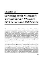
in Fig. B.1. Using this scheme, low-end PIC microcontrollers have anywhere from 25 to
73 unique file registers available to an application (see Table B.8).
There are a few things to note with low-end register addressing:
1 The OPTION and TRIS registers can be written to only by the option and tris
instructions, respectively.
Simpo PDF Merge and Split Unregistered Version -
PIC MICROCONTROLLER SUMMARY 1017
2 If the device has a built-in oscillator, the OSCCAL register is located in address 5,
which is normally the PORTA address.
3 The STATUS and OPTION registers are always the same for low-end devices.
4 The low-end PIC microcontroller FSR register can never equal zero.
MID-RANGE PIC MICROCONTROLLER REGISTERS
If you look at the different mid-range PIC microcontroller devices, you will see that
there is a great diversity in the register sets available to the various part numbers. This
is quite a bit different from the other three PIC MCU families, in which the registers
can be found at specific locations across the family. The diversity in the mid-range PIC
microcontroller family is caused by the myriad of different features that have been
released over the past few years, along with the number of different pin counts of the
various devices.
Despite this diversity, there are some standard addresses (listed in Table B.9) that
you can always count on with mid-range PIC microcontrollers. I always start with the
block of registers in bank 0 and bank 1 listed in the table and then add to them the fea-
tures that are built into the specific PIC microcontroller part number.
From these basic addresses, peripheral I/O registers (discussed below) are added
to the register banks, with file registers starting at either offset 0x0C or 0x20. For
most modern mid-range PIC microcontrollers, the file registers start at address 0x20
of the bank.
The specific part number datasheets will have to be checked to find where the file
registers that are shared across the banks are located.
Addr - Reg
Bank 0 Bank 1 Bank 2 Bank 3
Addr - Reg
Addr - Reg Addr - Reg
00 - INDF
01 - TMR0
02 - PCL
03 - STATUS
04 - FSR
05 - PORTA*
06 - PORTB
07 - PORTC
08-0F Shared
File Regs
10-1F Bank 0
File Regs
20 - INDF
21 - TMR0
22 - PCL
23 - STATUS
24 - FSR
25 - PORTA*
26 - PORTB
27 - PORTC
28-2F Shared
File Regs
30-3F Bank 1
File Regs
40 - INDF
41 - TMR0
42 - PCL
43 - STATUS
44 - FSR
45 - PORTA*
46 - PORTB
47 - PORTC
28-2F Shared
File Regs
50-4F Bank 2
File Regs
60 - INDF
61 - TMR0
62 - PCL
6
3 - STATUS
64 - FSR
65 - PORTA*
66 - PORTB
67 - PORTC
68-8F Shared
File Regs
70-7F Bank 3
File Regs
Shared
Registers
Bank Unique
Registers
* - “OSCCAL” may take place of “PORTA” in PICMicros
with In
ternal Oscillators
OPTION
TRIS#
- Accessed via “option” Instruction
- Accessed via “TRIS PORT#” Instruction
Figure B.1 The Low-End PIC microcontroller processor architecture
is limited to four banks of up to 32-byte-wide registers.
Simpo PDF Merge and Split Unregistered Version -
1018 APPENDIX B
TABLE B.8 LOW-END PIC MICROCONTROLLER REGISTER DEFINITIONS
ADDRESS REGISTER BITS BIT FUNCTION
0x003 STATUS 7 GPWUF—in PIC12C5xx and PIC16C505, when set,
reset from sleep on pin change; when set, power up
or _MCLR reset; in other devices, bit 7 is unused.
6–5 PA1–PA0—select the page to execute out of:
00—page 0 (0x0000–0x01FF)
01—page 1 (0x0200–0x03FF)
10—page 2 (0x0400–0x05FF)
11—page 3 (0x0600–0x07FF)
4 _TO—set after power up and clrwdt and sleep
instructions.
3 _PD—set after power up and clrwdt instruction; reset
after sleep instruction.
2 Z—set if the 8-bit result is equal to zero.
1 DC—set for low-order nybble carry after
addition or subtraction instruction.
0 C—set for carry after addition or subtraction instruction.
N/A OPTION 7 _GPWU—in PIC12C5xx or PIC16C505, reset to
enable wake-up on pin change; in other devices,
bit 7 is unused.
6 _GPPU—in PIC12C5xx or PIC16C505, enable pin
pull-ups; in other devices, bit 6 is unused.
5 T0CS—TMR0 clock source select; when set, T0CKI
pin is source; when reset, instruction clock.
4 T0SE—TMR0 edge select; when reset, increment
TMR0 on rising edge; when set, increment TMR0 on
falling edge.
3 PSA—prescaler assignment bit; when set, the
prescaler is assigned to the watchdog timer, else
TMR0.
2–0 PS2–PS0—prescaler rate select bits
Bit TMR0 rate:
111—256:1
110—128:1
101—64:1
100—32:1
011—16:1
010—8:1
001—4:1
000—2:1
Simpo PDF Merge and Split Unregistered Version -
PIC MICROCONTROLLER SUMMARY 1019
The STATUS register in mid-range PIC microcontroller is defined as listed in
Table B.10.
The OPTION register (which has the label OPTION_REG in the Microchip include
files) is defined in Table B.11.
Many devices have the PCON register (see Table B.12) that enhances the returned
information contained in the _TO and _PD bits of the STATUS register.
The PCLATH register’s contents (see Table B.13) are written to the program counter
each time a goto or call instruction is executed or if the contents of PCL are changed.
Some mid-range devices are now available with built-in RC oscillators. To make the
operation of the oscillators more accurate, the OSCCAL register is written to with a
factory-specified calibration value register as presented in Table B.14.
TABLE B.8 LOW-END PIC MICROCONTROLLER REGISTER DEFINITIONS (CONTINUED)
ADDRESS REGISTER BITS BIT FUNCTION
WDT rate:
64:1
32:1
16:1
8:1
4:1
2:1
1:1
TABLE B.9 MID-RANGE BANK 0/BANK 1 REGISTER DEFINITIONS
OFFSET BANK 0 BANK 1 COMMENTS
0x00 INDF INDF
0x01 TMR0 OPTION
0x02 PCL PCL
0x03 STATUS STATUS
0x04 FSR FSR
0x05 PORTA TRISA
0x06 PORTB TRISB
0x07 PORTC TRISC Available in 28/40-pin parts
0x08 PORTD TRISD Available in 40-pin parts
0x09 PORTE TRISE Available in 40-pin parts
0x0A PCLATH PCLATH
0x0B INTCON INTCON
Simpo PDF Merge and Split Unregistered Version -
1020 APPENDIX B
TABLE B.10 MID-RANGE STATUS REGISTER DEFINITION
BIT FUNCTION
7 IRP—FSR select between the high and low register banks
6–5 RP1–RP0—direct addressing select banks (0–3)
4 _TO—Time-out bit; reset after a watchdog timer reset
3 _PD—Power-down active bit; reset after sleep instruction
2 Z—set when the 8-bit result is equal to zero
1 DC—set when the low nybble of addition/subtraction result carries
to the high nybble
0 C—set when the addition/subtraction result carries to the next byte;
also used with the rotate instructions
TABLE B.11 MID-RANGE OPTION REGISTER DEFINITION
BIT FUNCTION
7 _RBPU—when reset, the PORTB pin pull-up is enabled.
6 INTEDG—when set, interrupt request on rising edge of RB0/INT pin.
5 T0CS—when set, TMR0 is incremented from the T0CKI pin, else by
the internal instruction clock.
4 T0SE—when set, TMR0 is incremented on the high to low (falling
edge) of T0CKI.
3 PSA—prescaler assignment bit; when set, the prescaler is assigned
to the watchdog timer, else to TMR0.
2–0 PS2–PS0—prescaler rate select.
Bit TMR0 Rate WDT Rate
111 256:1 128:1
110 128:1 64:1
101 64:1 32:1
000 32:1 16:1
011 16:1 8:1
010 8:1 4:1
001 4:1 2:1
000 2:1 1:1
Simpo PDF Merge and Split Unregistered Version -
PIC MICROCONTROLLER SUMMARY 1021
Interrupts are controlled from the INTCON register (see Table B.15), which con-
trols the basic mid-range PIC microcontroller interrupts as well as access to enhanced
interrupt features.
Bit 6 of INTCON may be a peripheral device interrupt enable/request bit, or it can
be PEIE, which when set will enable peripheral interrupts set in the PIR and PIE reg-
isters. The PIR register(s) contains the F bits (interrupt request active), whereas PIE
contains the E bits (interrupt request enable). As I work through the different periph-
erals, the E and F bits will be listed, but their actual location is part number–specific,
and the datasheet will have to be consulted.
Data EEPROM is accessed via the EEADR and EEDATA registers, with EECON1
(see Table B.16) and EECON2 providing the access control. EECON2 is a pseudoreg-
ister, and the act of writing to it is used to verify that the operation request is valid.
The data EEPROM write interrupt request bit (EEIE) is either in a PIE register or
INTCON. The parallel slave port (PSP; available only in 40-pin mid-range PIC micro-
controllers and listed in Table B.17) is enabled by setting the PSPMODE bit. Interrupt
request are enabled by the PSPIE flag and requested by the PSPIF flag of the PIE and
PIR registers, respectively. The parallel slave port is controlled from TRISE. Note that
when the parallel slave port is enabled, PORTD and PORTE cannot be used for I/O.
TABLE B.12 MID-RANGE PCON REGISTER DEFINITION
BIT FUNCTION
7 MPEEN—set if there is a memory parity error; this capability is
built into a small number of PIC microcontrollers.
6–3 Unused
2 _PER—reset when there was a program memory parity error; this
capability is built into a small number of PIC microcontrollers.
1 _POR—reset when execution is from a power-on reset.
0 _BOR—reset when execution is from a brown-out reset.
TABLE B.13 MID-RANGE PCLATH REGISTER DEFINITION
BIT FUNCTION
7–5 Unused.
4 Select high and low pages.
3 Select odd or even pages.
2–0 Select the 256-instruction address block within current
page; this data is used when PCL is written to directly.
Simpo PDF Merge and Split Unregistered Version -
1022 APPENDIX B
Along with TMR0, some mid-range PIC microcontrollers have TMR1 and TMR2,
which are used for basic timing operations as well as CCP (compare, capture, and
PWM) I/O. TMR1 is a 16-bit-wide register (accessed via TMR1L and TMR1H) that
will request an interrupt on overflow (TMR1IF) if the TMR1IE bit is set. The T1CON
register (shown in Table B.18) controls the operation of TMR1.
TMR2 is an 8-bit register that is continually compared against a value in the PR2
register. To have TMR2 operate like TMR0 as an 8-bit timer with a range of 0x000 to
0x0FF, then the PR2 (the register TMR2 is compared against) is set to 0x000. The
TMR2 output can be used to drive a PWM signal out. Interrupts (TMR2IF) can be
requested after the TMR2 overflow has passed through a postscaler and TMR2IE is
set. The T2CON register (see Table B.19) controls the operation of TMR2.
TMR1 and TMR2 are used with one of the two CCP (capture/compare/PWM) mod-
ules for advanced I/O. TMR1 is used for capture and compare, and TMR2 is used for
PWM output. The CCPR2x registers are used for storing compare/capture values, and
the CCPx register specifies the pin used for CCP. The CCPxCON register (shown in
Table B.20) is used for controlling CCP operation.
TABLE B.14 MID-RANGE OSCCAL REGISTER DEFINITION
BIT FUNCTION
7–4 CAL3:CAL0—16-bit calibration value.
3 CALFST—increase the speed of the RC oscillator.
2 CALSLW—decrease the speed of the RC oscillator.
1–0 Unused.
TABLE B.15 MID-RANGE INTCON REGISTER DEFINITION
BIT FUNCTION
7 GIE—global interrupt enable; for any interrupt requests
to be acknowledged, this bit must be set.
6 Device-specific interrupt enable (see below).
5 T0IE—TMR0 interrupt overflow request enable.
4 INTE—RB0/INT pin interrupt request enable.
3 RBIE—PORTB change interrupt request enable.
2 T0IF—TMR0 interrupt overflow request.
1 INTF—RB0/INT pin interrupt request.
0 RBIF—PORTB change interrupt request.
Simpo PDF Merge and Split Unregistered Version -
PIC MICROCONTROLLER SUMMARY 1023
TABLE B.16 MID-RANGE EECON1 REGISTER DEFINITION
BIT FUNCTION
7–5 Unused.
4 EEIF—EEPROM write complete interrupt request.
3 WRERR—bit set when EEPROM write was invalid.
2 WREN—set to enabling writing to EEPROM.
1 WR—write control bit.
0 RD—set to allow an EEPROM data read.
TABLE B.17 MID-RANGE PSP REGISTER DEFINITION
BIT FUNCTION
7 IBF—bit set when a word has been written into the PIC
microcontroller and has not been read.
6 OBF—bit set when a byte has been written to the
PORTD output register and has not been read.
5 IBOV—bit set when a word has been written into the PIC
microcontroller before the previous one has been read.
4 PSPMODE—bit set to enable parallel slave port.
3 Unused.
2 TRISE2—TRIS bit for E2.
1 TRISE1—TRIS bit for E1.
0 TRISE0—TRIS bit for E0
TABLE B.18 MID-RANGE T1CON REGISTER DEFINITION
BIT FUNCTION
7–6 Unused.
T1CKPS1–T1CKPS2—TMR1 input prescaler select.
3 T1OSCEN—set to enable external TMR1 oscillator.
2 _T1SYNCif external clock used for TMR1, then synchro-
nize to it when this bit is reset.
1 TMR1CS—when set, TMR1 is driven by external
clock/TMR1 oscillator.
0 TMR1ON—set to enable TMR1.
Simpo PDF Merge and Split Unregistered Version -
1024 APPENDIX B
CCP interrupts are requested via the CCPxIF flag and enabled by the CCPXIE flag,
where x is 1 or 2 depending on the active CCP module. There are three different SSP
modules built into the PIC microcontroller. Each one provides somewhat different
options, and understanding how they work will be critical to your applications and if
I2C is going to be used with them. The basic SSP modules (SSP and BSSP) provide a
full SPI interface and I2C slave mode interface. The SSPBUF register provides simple
TABLE B.19 MID-RANGE T2CON REGISTER DEFINITION
BIT FUNCTION
7 Unused.
6–3 TOUTPS3–TOUTPS0—TMR2 output postscaler select.
Bit Postscaler
1111 16:1
1110 15:1
1101 14:1
1100 13:1
1011 12:1
1010 11:1
1001 10:1
1000 9:1
0111 8:1
0110 7:1
0101 6:1
0100 5:1
0011 4:1
0010 3:1
0001 2:1
0000 1:1
2 TMR2ON—set to enable TMR2.
1–0 T2CKPS1–T2CKPS0—TMR2 input prescaler select.
Bit Prescaler
1x 16:1
01 4:1
00 1:1
Simpo PDF Merge and Split Unregistered Version -
PIC MICROCONTROLLER SUMMARY 1025
buffering, with the SSPADD buffers providing the received address for comparing
against I/O operations. To control the operation of the SSP, the SSPCON register
(defined in Table B.21) is used.
The SSPSTAT register (see Table B.22) is also used to control the SSP.
The master SSP (MSSP) accesses similar registers for the same functions with a
second SSPCON register. The important difference between the MSSP and the other
SSP modules is the enabled I2C master hardware in the MSSP. The MSSP’s SSP-
CON1 register is defined as shown in Table B.23.
SSPCON2 is used for I2C master mode and is defined in Table B.24.
The SSPSTAT register for MSSP is shown in Table B.25.
Interrupts are requested from the SSP via the SSPIF bit and enabled by the SSPIE
bit. Nonreturn to zero (NRZ) asynchronous serial communications are accomplished by
the built-in USART. This circuit also can be used for synchronous serial communica-
tions. The clock speed is determined by SPBRG. The TXREG and RCREG registers
TABLE B.20 MID-RANGE CCPXCON REGISTER DEFINITION
BIT FUNCTION
7–6 Unused.
5–4 DCxB1–DCxB0—PWM duty cycle bit 1 and bit 0; these bits are only
accessed by the PWM for its low-output values.
3–0 CCPxM3–CCPxM0—CCPx mode select.
Bit Function
11xx PWM mode
1011 Compare mode, trigger special event
1010 Compare mode, trigger on compare match
1001 Compare mode, initialize CCP pin high; on compare,
match force CCP low
1000 Compare mode, initialize CCP pin low; on compare,
match force CCP high
0111 Capture on every 16th rising edge
0110 Capture on every 4th rising edge
0101 Capture on every rising edge
0100 Capture on every falling edge
001x Unused
0001 Unused
0000 Capture/compare/PWM off
Simpo PDF Merge and Split Unregistered Version -
1026 APPENDIX B
are used to transfer data. The RCSTA is the primary USART control register and is
defined in Table B.26. TXSTA is defined in Table B.27.
The RCIF interrupt request bit, when set, means that there is a character received in
the USART. RCIF is enabled by RCIE. TXIF is set when the TX holding register is
empty and is enabled by TXIE.
Comparator-equipped PIC microcontrollers have a built-in reference voltage source
that is controlled by the VRCON register (see Table B.28).
The voltage reference output is defined by the formula:
Vref = [1/4 * Vdd * (1 – VRR)] + Vdd * (VR3:VR0/{24 + [8 * (1 – VRR)]})
For Vdd equal to 5.0 V, Table B.29 lists different Vref values.
The voltage reference is normally used with the voltage comparator, which is con-
trolled by the CMCON Register defined in Table B.30.
TABLE B.21 MID-RANGE SSPCON REGISTER DEFINITION
BIT FUNCTION
7 WCOL—set if SSPBUF was written to while transmitting data or not
in correct mode for transmit.
6 SSPOV—set when SSP receive overflow occurs.
5 SSPEN—enables pins for SSP mode.
4 CKP—in SPI, set for idle clock high; in I2C mode, set to enable clock.
3–0 SSPM3–SSPM0—SSP mode select:
1111—I2C slave mode, 10-bit address
1110—I2C slave mode, 7-bit address
110x—Reserved
1011—I2C firmware-controlled master
1010—Reserved
1001—Reserved
1000—Reserved
0111—I2C slave mode, 10-bit address
0110—I2C slave mode, 7-bit address
0101—SSP slave, _SS disabled
0100—SSP slave, _SS enabled
0011—SPI master, clock = TMR2
0010—SPI master, Fosc/64
0001—SPI master, Fosc/16
0000—SPI master, Fosc/4
Simpo PDF Merge and Split Unregistered Version -
PIC MICROCONTROLLER SUMMARY 1027
Interrupts requested by change on comparator outputs are specified by CMIF and
enabled by CMIE. There are also some analog-to-digital converter (ADC) options that
can be used with the PIC microcontroller. Operation of the ADC is controlled by the
ADCON0 register (see Table B.31).
Selecting the PORTA, analog/digital functions, there are a number of different for-
mats of ADCON1 that you should be aware of. For basic 18-pin PIC microcontroller
ADCs, ADCON1 is defined in Table B.32.
TABLE B.22 MID-RANGE SSPSTAT REGISTER DEFINITION
BIT FUNCTION
7 SMP—data sampled at end of data output time if set, else middle.
6 CKE—data transmitted on rising edge of SCK when set.
5 D/_A—ssed by I2C; when set, indicates last byte transferred was data;
when reset, indicates last byte transferred was address.
4 P—set when stop bit detected.
3 S—set when start bit indicated.
2 R/_W—set when command received was a read.
1 UA—set when application must update SSPADD register.
0 BF—set when buffer is full in RX and when TX is in process.
TABLE B.23 MID-RANGE MSSP SSPCON1 REGISTER DEFINITION
BIT FUNCTION
7 WCOL—set if SSPBUF was written to while transmitting data or not in
correct mode for transmit.
6 SSPOV—set when SSP receive overflow occurs.
5 SSPEN—enables pins for SSP mode.
4 CKP—in SPI, set for idle clock high; in I2C mode, set to enable clock.
3–0 SSPM3–SSPM0—SSP mode select.
1xx1—Reserved
1x1x—Reserved
1000—I2C master mode, clock = Fosc/[4 * (SSPADD + 1)]
0111—I2C slave mode, 10-bit address
0110—I2C slave mode, 7-bit address
0101—SSP slave, _SS disabled.
Simpo PDF Merge and Split Unregistered Version -
1028 APPENDIX B
TABLE B.24 MID-RANGE MSSP SSPCON2 REGISTER DEFINITION
BIT FUNCTION
7 GCEN—set to enable interrupt when general call address is received.
6 ACKSTAT—set when acknowledge received from I2C slave device.
5 ACKDT—reset to send acknowledge at the end of a byte receive.
4 ACKEN—acknowledge I2C sequence when set.
3 RCEN—set to enable I2C receive mode.
2 PEN—reset to initiate stop condition on I2C clock and data.
1 RSEN—set to initiate repeated start condition on I2C clock and data.
0 SEN—set to initiate start condition on I2C clock and data.
TABLE B.25 MID-RANGE MSSP SSPSTAT REGISTER DEFINITION
BIT FUNCTION
7 SMP—data sampled at end of data output time if set, else middle.
6 CKE—data transmitted on rising edge of SCK when set.
5 D/_A—used by I2C; when set, indicates last byte transferred was data;
when reset, indicates last byte transferred was address.
4 P—set when stop bit detected.
3 S—set when start bit indicated.
2 R/_W—set when command received was a read.
1 UA—set when application must update SSPADD register.
0 BF—set when buffer is full in RX and when TX is in pr.
TABLE B.26 MID-RANGE RCSTA REGISTER DEFINITION
BIT FUNCTION
7 SPEN—set to enable the USART.
6 RX9—set to enable 9-bit serial reception.
5 SREN—set to enable single receive for synchronous mode.
4 CREN—set to enable continuous receive mode.
3 ADDEN—enables address detection in asynchronous mode.
2 FERR—framing error bit.
1 OERR—set after overrun error.
0 RX9D—ninth bit of data received.
Simpo PDF Merge and Split Unregistered Version -
PIC MICROCONTROLLER SUMMARY 1029
For more advanced 18-pin PIC microcontrollers, ADCON1 is defined as shown
in Table B.33.
Both 28- and 40-pin PIC microcontrollers have the ADCON1 register, as defined
in Table B.34.
The result of the ADC operation is stored in ADRES, and ADIF is set on comple-
tion of the ADC operation to request an interrupt if ADIE is set. Moreover, 10-bit
ADCs are also available in the PIC microcontroller, with a different ADCON1 regis-
ter (see Table B.35).
In the case of 10-bit ADCs, the result is stored in ADRESL and ADRESH. This
mid-range register list does not include the PIC16C92x’s LED control registers. This,
as well as any other I/O hardware registers that were not available when this appendix
was written, can be found in the Microchip datasheets.
TABLE B.27 MID-RANGE TXSTA REGISTER DEFINITION
BIT FUNCTION
7 CSRC—set for synchronous clock generated internally.
6 TX9—set to enable 9-bit data transmission
5 TXEN—set to enable transmit.
4 SYNC—set to select synchronous mode.
3 Unused.
2 BRGH––Set to Select the High Baud Rate
1 TRMT—set when transmit shift register is empty.
0 TX9D—Ninth bit of transmit data.
TABLE B.28 MID-RANGE VRCON REGISTER DEFINITION
BIT FUNCTION
7 VREN—set to turn on voltage reference circuit
6 VROE—set to output voltage reference externally.
5 VRR—set for low-voltage reference range; reset for
high-voltage reference range.
4 Unused.
3–0 VR3–VR0—Select the reference voltage output
Simpo PDF Merge and Split Unregistered Version -
1030 APPENDIX B
PIC18
The unique hardware registers built into the PIC18 are defined in Table B.36. Note
that these registers are accessed either via the access bank or by using the BSR set to
0x0F. If the registers are to be accessed using the FSR register, then the high nybble
is set to 0x0F. For this reason, I have set the first nybble of the 12-bit address as # in
Table B.36. If the access bank is used, then there is no high nybble to the address. If
the BSR or FSR registers are used for addressing, then # is F.
The PIC18 microcontroller chips are designed with many of the same macros as the
mid-range devices. This means that the peripheral functions generally are constructed
and accessed in exactly the same way as in the mid-range chips. In the interests of
brevity, I have not listed the specific I/O registers in the PIC18 register list because the
register/function definitions can be found in the preceding section.
Device Pinouts
In the following sections of this appendix I have tried to generalize the pinouts for var-
ious PIC microcontroller part numbers. These graphics are meant to represent how the
pins are specified for the different part numbers and do not reflect the actual dimen-
sions of the parts.
TABLE B.29 VRCON VALUES TO VOLTAGE OUTPUT
VR3:VR0 VRR = 1 VRR = 0
1111 3.13 V 3.59 V
1110 2.92 V 3.44 V
1101 2.71 V 3.28 V
1100 2.50 V 3.13 V
1011 2.29 V 2.97 V
1010 2.08 V 2.81 V
1001 1.88 V 2.66 V
1000 1.67 V 2.50 V
0111 1.46 V 2.34 V
0110 1.25 V 3.19 V
0101 1.04 V 2.03 V
0100 0.83 V 1.88 V
0011 0.63 V 1.72 V
0010 0.42 V 1.56 V
0001 0.21 V 1.41 V
0000 0.00 V 1.25 V
Simpo PDF Merge and Split Unregistered Version -
PIC MICROCONTROLLER SUMMARY 1031
As a rule of thumb, pin-through-hole (PTH) parts (P and JW) are standard 0.300-
and 0.600-in widths with pins 0.100 in apart in dual in-line packages. The height of
the device depends on the package used. I use PTH parts for all the applications pre-
sented in this book because of the ease with which they can be handled, programmed,
and assembled into circuits.
Surface-mount-technology (SMT) parts are either in dual in-line packages (SO) or
in quad plastic chip carriers (PT, PQ, and L).
For actual device dimensions, check the datasheets (on the Microchip web site)
for the PIC microcontroller that you are planning on using. Different packages for
different PIC microcontrollers have different via, pad, and clearance specifications.
LOW-END
When describing low-end PIC microcontrollers, I also include the PIC12C50x and the
PIC16C505, which do use the low-end PIC microcontroller processor architecture but
are programmed using the mid-range’s ICSP protocol. There are no PLCC or QFP
packages used for low-end devices, and the pinouts remain the same whether or not
the PIC microcontroller is in an SMT or PTH package.
TABLE B.30 MID-RANGE CMCON REGISTER DEFINITION
BIT FUNCTION
7 C2OUT—set when C2Vin+ is greater than C2Vin–.
6 C1OUT—set when C1Vin+ is greater than C1Vin–.
5–4 Unused.
3 CIS—comparator input switch; see CM2–CM0.
2–0 CM2–CM0—comparator mode select bits:
CIS C1Vin+ C1Vin– C2Vin+ C2Vin– Comments
111 x Gnd Gnd Gnd Gnd Comparators off
110 x AN2 AN0 AN2 AN1 AN3 = C1OUT,
RA4 = C2OUT
101 x Gnd Gnd AN2 AN1
100 x AN3 AN0 AN2 AN1
011 x AN2 AN0 AN2 AN1
010 1 Vref AN3 Vref AN2
010 0 Vref AN0 Vref AN1
001 1 AN2 AN3 AN2 AN1
001 0 AN2 AN0 AN2 AN1
000 x AN3 AN0 AN2 AN1 Comparators off
Simpo PDF Merge and Split Unregistered Version -
1032 APPENDIX B
MID-RANGE
The mid-range devices have the widest range of pinouts of any of the PIC microcon-
troller families. In the following figures, I have given the 8-, 14-, 18-, 28-, and 40-pin
packages for the most popular devices, as well as the SMT packaging for the 40-pin
devices.
TABLE B.31 MID-RANGE ADCON0 REGISTER DEFINITION
BIT FUNCTION
7–6 ADCS1–ADCS0—ADC conversion clock select:
11—internal RC oscillator
10—divide PIC microcontroller clock by 32
01—divide PIC microcontroller clock by 8
00—divide PIC microcontroller clock by 2
5–3 CHS2–CHS0—ADC conversion channel select bits:
111—AN7
110—AN6
101—AN5
100—AN4
011—AN3
010—AN2
001—AN1
000—AN0
2 GO/_DONE—set to start A/D conversion; reset by
hardware when conversion before.
1 Unused.
0 ADON—set to turn on the ADC function unused.
TABLE B.32 MID-RANGE BASIC ADCON1 REGISTER DEFINITION
BIT FUNCTION
Unused.
1–0 PCFG1–PCFG0—A/D select:
Bit AN3 AN2 AN1 AN0
11 D D D D
10 D D A A
01 Vref+ A A A
00 A A A A
Simpo PDF Merge and Split Unregistered Version -
PIC MICROCONTROLLER SUMMARY 1033
For many of the devices, the pinout is similar, but the pin functions may be differ-
ent. In these cases I have marked the pins with an asterisk to show that these pins have
optional other purposes. If you are not sure of what a PIC microcontroller pin is for,
check the datasheets included on the CD-ROM that came with this book or the
datasheets at the Microchip web site.
TABLE B.33 MID-RANGE ADVANCED ADCON1
REGISTER DEFINITION
BIT FUNCTION
7–3 Unused.
2–0 PCFG2–PCFG0—A/D select:
Bit AN3 AN2 AN1 AN0
111 D D D D
110 D D D A
101 D D Vref+ A
100 D D A A
011 D A Vref+ A
010 D A A A
001 A A Vref+ A
000 A A A A
TABLE B.34 MID-RANGE TWENTY-EIGHT/FORTY PIN PIC
MICROCONTROLLER ADCON1 REGISTER DEFINITION
BIT FUNCTION
7–3 Unused.
2–0 PCFG2–PCFG0—A/D select:
Bit AN7 AN6 AN5 AN4 AN3 AN2 AN1 AN0
11x D D D D D D D D
101 D D D D Vref+ D A A
100 D D D D A D A A
011 D D A A Vref+ A A A
010 D D D A A A A A
001 A A A A Vref+ A A A
000 A A A A A A A A
Simpo PDF Merge and Split Unregistered Version -
1034 APPENDIX B
The PIC14000, which is designed for “mixed signals,” uses the 28-pin packaging of
the standard devices, but the pinouts are different, as shown in Fig. B.13.
The PIC16C92x LCD driver microcontrollers are fairly high pin count devices.
Figure B.14 shows the 64-pin dual in-line package (DIP) part. There is also a PLCC
and TQFP package for the parts as well.
PIC18
There is a lot of similarity between the mid-range PIC microcontroller’s pinouts and
the PIC18 parts, as will be seen in the following figures.
TABLE B.35 MID-RANGE 10-BIT ADC ADCON1 REGISTER DEFINITION
BIT FUNCTION
7–6 Unused.
5 ADFM—when set, the result is right-justified, else left-justified.
4 Unused.
3–0 PCFG3–PCFG0—A/D select;
Bits AN7 AN6 AN5 AN4 AN3 AN2 AN1 AN0 VR+ VR–
1111 D D D D VR+ VR– D A AN3 AN2
1110 D D D D D D D A Vdd Vss
1101 D D D D VR+ VR– A A AN3 AN2
1100 D D D A VR+ VR– A A AN3 AN2
1011 D D A A VR+ VR– A A AN3 AN2
1010 D D A A VR+ A A A AN3 Vss
1001 D D A A A A A A Vdd Vss
1000 A A A A VR+ VR– A A AN3 AN2
011x D D D D D D D D N/A N/A
0101 D D D D VR+ D A A AN3 Vss
0100 D D D D A D A A Vdd Vss
0011 D D D D VR+ A A A AN3 Vss
0010 D D D A A A A A Vdd Vss
0001 A A A A VR+ A A A AN3 Vss
0000 A A A A A A A A Vdd Vss
Simpo PDF Merge and Split Unregistered Version -
TABLE B.36 PIC18 REGISTER DEFINITION
ADDRESS REGISTER FUNCTION/BIT DEFINITION
0x0#80 PORTA PORTA read/write register; pin options are as follows:
Bit Function
7 Unused
6 OSC2
5 Slave select/optional AN4
4 Open-drain output/Schmidt-trigger input
3–0 Optional AN3–AN0
0x0#81 PORTB PORTB read/write register; I/O pins can be pulled by software; pin options
are defined as follows:
Bit Function
7–6 ICSP programming pins/interrupt on pin change
5 Interrupt on pin change
4 Interrupt on pin change
3 CCP2 I/O and PWM output
2 Interrupt source 3
1 Interrupt source 2
0 Interrupt source 1
0x0#82 PORTC PORTC read/write registers; I/O pins have Schmidt-trigger inputs;
pin options are as follows:
Bit Function
7 UART receive pin
6 UART transmit pin
5 Synchronous serial port data
4 SPI data or I2C data
3 SPI clock or I2C clock
2 CCP1 I/O and PWM output/TMR1 clock output
0 TMR1 clock input
(
Continued
)
1035
Simpo PDF Merge and Split Unregistered Version -
1036
TABLE B.36 PIC18 REGISTER DEFINITION (CONTINUED)
ADDRESS REGISTER FUNCTION/BIT DEFINITION
0x0#83 PORTD PORTD only available on 40-pin PIC18 devices; Schmidt-trigger inputs;
used for data slave port.
0x0#84 PORTE PORTE only available on 40-pin PIC18; Schmidt-trigger inputs for I/O
mode; used for data slave port as follows:
Bit Function
7–3 Unused
2 Negative active chip select
1 Negative active write enable to PIC18Cxx
0 Negative active output enable (_RD) from PIC18Cxx
0x0#89 LATA Data output latch/bypassing PORTA
0x0#8A LATB Data output latch/bypassing PORTB
0x0#8B LATC Data output latch/bypassing PORTC
0x0#8C LATD Data output latch/bypassing PORTD; only available on 40-pin PIC18
0x0#8D LATE Data output latch/bypassing PORTE; only available on 40-pin PIC18
0x0#92 TRISA I/O pin tristate control register; set bit to 0 for output mode.
0x0#93 TRISB I/O pin tristate control register; set bit to 0 for output mode.
0x0#94 TRISC I/O pin tristate control register; set bit to 0 for output mode.
0x0#95 TRISD I/O pin tristate control register; only available on 40-pin PIC18; set bit to
0 for output mode.
0x0#96 TRISE I/O pin tristate control register; only available on 40-pin PIC18; set bit to
0 for output mode; special function bits specified as follows;
Bit Function
7 IBF—set when PSP is enabled and a byte has been written to
the PIC microcontroller
6 OBF—set when PSP is enabled and a byte output has not been
read from the chip
Simpo PDF Merge and Split Unregistered Version -
1037
5 IBOV—set when PSP is enabled and the byte written has been
overwritten by a subsequent byte
4 PSPMODE—set to enable PIC microcontroller’s PSP I/O port
3 Unused
2 TRISE2—TRIS bit for RE2
1 TRISE1—TRIS bit for RE1
0 TRISE0—TRIS bit for RE0
0x0#9D PIE1 Peripheral interrupt enable register:
Bit Function
7 PSPIE—set to enable PSP interrupt request on read/write
6 ADIE—set to enable interrupt request on completion of A/D
operation
5 RCIE—set to enable interrupt request on USART data receive
4 TXIE—set to enable interrupt request on USART transmit holding
register empty
3 SSPIE—master synchronous serial port interrupt enable bit
2 CCP1IE—set to enable CCP1 interrupt request enable
1 TMR2IE—TMR2 to PR2 match interrupt request enable
0 TMR1IE—TMR1 overflow interrupt request enable
0x0#9E PIR1 Peripheral interrupt request register:
Bit Function
7 PSPIF—set on PSP read/write
6 ADIF—set when A/D complete
5 RCIF—set on USART data receive
4 TXIF—set on USART transmit holding register empty
3 SSPIF—set on synchronous serial port data transmission/
reception complete
2 CCP1IF—set on TMR1 capture or compare match
1 TMR2IF—set on TMR2 to PR2 match
0 TMR1IF—set on TMR1 overflow
(
Continued
)
Simpo PDF Merge and Split Unregistered Version -