Electromagnetic Waves and Antennas combined - Chapter 4 pdf
Bạn đang xem bản rút gọn của tài liệu. Xem và tải ngay bản đầy đủ của tài liệu tại đây (229.54 KB, 11 trang )
4
Propagation in Birefringent Media
4.1 Linear and Circular Birefringence
In this chapter, we discuss wave propagation in anisotropic media that are linearly or cir-
cularly birefringent. In such media, uniform plane waves can be decomposed in two or-
thogonal polarization states (linear or circular) that propagate with two different speeds.
The two states develop a phase difference as they propagate, which alters the total po-
larization of the wave. Such media are used in the construction of devices for generating
different polarizations.
Linearly birefringent materials can be used to change one polarization into another,
such as changing linear into circular. Examples are the so-called uniaxial crystals, such
as calcite, quartz, ice, tourmaline, and sapphire.
Optically active or chiral media are circularly birefringent. Examples are sugar solu-
tions, proteins, lipids, nucleic acids, amino acids, DNA, vitamins, hormones, and virtually
most other natural substances. In such media, circularly polarized waves go through
unchanged, with left- and right-circular polarizations propagating at different speeds.
This difference causes linearly polarized waves to have their polarization plane rotate
as they propagate—an effect known as natural optical rotation.
A similar but not identical effect—the Faraday rotation—takes place in gyroelec-
tric media, which are ordinary isotropic materials (glass, water, conductors, plasmas)
subjected to constant external magnetic fields that break their isotropy. Gyromagnetic
media, such as ferrites subjected to magnetic fields, also become circularly birefringent.
We discuss all four birefringent cases (linear, chiral, gyroelectric, and gyromagnetic)
and the type of constitutive relationships that lead to the corresponding birefringent
behavior. We begin by casting Maxwell’s equations in different polarization bases.
An arbitrary polarization can be expressed uniquely as a linear combination of two
polarizations along two orthogonal directions.
†
For waves propagating in the z-direction,
we may use the two linear directions
{
ˆ
x,
ˆ
y}, or the two circular ones for right and left
polarizations
{
ˆ
e
+
,
ˆ
e
−
}, where
ˆ
e
+
=
ˆ
x − j
ˆ
y and
ˆ
e
−
=
ˆ
x + j
ˆ
y.
‡
Indeed, we have the
following identity relating the linear and circular bases:
†
For complex-valued vectors e
1
, e
2
, orthogonality is defined with conjugation: e
∗
1
·e
2
= 0.
‡
Note that
ˆ
e
±
satisfy:
ˆ
e
∗
±
·
ˆ
e
±
= 2,
ˆ
e
∗
+
·
ˆ
e
−
= 0,
ˆ
e
+
×
ˆ
e
−
= 2j
ˆ
z, and
ˆ
z
×
ˆ
e
±
=±j
ˆ
e
±
.
132 4. Propagation in Birefringent Media
E =
ˆ
x E
x
+
ˆ
y E
y
=
ˆ
e
+
E
+
+
ˆ
e
−
E
−
, where E
±
=
1
2
(E
x
±jE
y
) (4.1.1)
The circular components
E
+
and E
−
represent right and left polarizations (in the
IEEE convention) if the wave is moving in the positive
z-direction, but left and right if it
is moving in the negative
z-direction.
Because the propagation medium is not isotropic, we need to start with the source-
free Maxwell’s equations before we assume any particular constitutive relationships:
∇
∇
∇×E =−jωB , ∇
∇
∇×H = jωD , ∇
∇
∇·D = 0 , ∇
∇
∇·B = 0 (4.1.2)
For a uniform plane wave propagating in the
z-direction, we may replace the gradient
by
∇
∇
∇=
ˆ
z ∂
z
. It follows that the curls ∇
∇
∇×E =
ˆ
z ×∂
z
E and ∇
∇
∇×H =
ˆ
z ×∂
z
H will be
transverse to the
z-direction. Then, Faraday’s and Amp
`
ere’s laws imply that D
z
= 0
and
B
z
= 0, and hence both of Gauss’ laws are satisfied. Thus, we are left only with:
ˆ
z
×∂
z
E =−jωB
ˆ
z
×∂
z
H = jωD
(4.1.3)
These equations do not “see” the components
E
z
,H
z
. However, in all the cases that
we consider here, the conditions
D
z
= B
z
= 0 will imply also that E
z
= H
z
= 0. Thus,
all fields are transverse, for example, E
=
ˆ
x E
x
+
ˆ
y E
y
=
ˆ
e
+
E
+
+
ˆ
e
−
E
−
. Equating x, y
components in the two sides of Eq. (4.1.3), we find in the linear basis:
∂
z
E
x
=−jωB
y
,∂
z
E
y
= jωB
x
∂
z
H
y
=−jωD
x
,∂
z
H
x
= jωD
y
(linear basis) (4.1.4)
Using the vector property
ˆ
z
×
ˆ
e
±
=±j
ˆ
e
±
and equating circular components, we
obtain the circular-basis version of Eq. (4.1.3) (after canceling some factors of
j):
∂
z
E
±
=∓ωB
±
∂
z
H
±
=±ωD
±
(circular basis) (4.1.5)
4.2 Uniaxial and Biaxial Media
In uniaxial and biaxial homogeneous anisotropic dielectrics, the D−E constitutive rela-
tionships are given by the following diagonal forms, where in the biaxial case all diagonal
elements of the permittivity matrix are distinct:
⎡
⎢
⎣
D
x
D
y
D
z
⎤
⎥
⎦
=
⎡
⎢
⎣
e
00
0
o
0
00
o
⎤
⎥
⎦
⎡
⎢
⎣
E
x
E
y
E
z
⎤
⎥
⎦
and
⎡
⎢
⎣
D
x
D
y
D
z
⎤
⎥
⎦
=
⎡
⎢
⎣
1
00
0
2
0
00
3
⎤
⎥
⎦
⎡
⎢
⎣
E
x
E
y
E
z
⎤
⎥
⎦
(4.2.1)
For the uniaxial case, the
x-axis is taken to be the extraordinary axis with
1
=
e
,
whereas the
y and z axes are ordinary axes with permittivities
2
=
3
=
o
.
The ordinary
z-axis was chosen to be the propagation direction in order for the
transverse
x, y axes to correspond to two different permittivities. In this respect, the
4.2. Uniaxial and Biaxial Media 133
uniaxial and biaxial cases are similar, and therefore, we will work with the biaxial case.
Setting
D
x
=
1
E
x
and D
y
=
2
E
y
in Eq. (4.1.4) and assuming B = μ
0
H, we have:
∂
z
E
x
=−jωμ
0
H
y
,∂
z
E
y
= jωμ
0
H
x
∂
z
H
y
=−jω
1
E
x
,∂
z
H
x
= jω
2
E
y
(4.2.2)
Differentiating these once more with respect to
z, we obtain the decoupled Helmholtz
equations for the
x-polarized and y-polarized components:
∂
2
z
E
x
=−ω
2
μ
0
1
E
x
∂
2
z
E
y
=−ω
2
μ
0
2
E
y
(4.2.3)
The forward-moving solutions are:
E
x
(z)= Ae
−jk
1
z
,k
1
= ω
√
μ
0
1
= k
0
n
1
E
y
(z)= Be
−jk
2
z
,k
2
= ω
√
μ
0
2
= k
0
n
2
(4.2.4)
where
k
0
= ω
√
μ
0
0
= ω/c
0
is the free-space wavenumber and we defined the refractive
indices
n
1
=
1
/
0
and n
2
=
2
/
0
. Therefore, the total transverse field at z = 0 and
at distance
z = l inside the medium will be:
E
(0) =
ˆ
x A +
ˆ
y B
E(l) =
ˆ
x Ae
−jk
1
l
+
ˆ
y Be
−jk
2
l
=
ˆ
x A +
ˆ
y Be
j(k
1
−k
2
)l
e
−jk
1
l
(4.2.5)
The relative phase
φ = (k
1
−k
2
)l between the x- and y-components introduced by
the propagation is called retardance:
φ = (k
1
−k
2
)l = (n
1
−n
2
)k
0
l = (n
1
−n
2
)
2πl
λ
(4.2.6)
where
λ is the free-space wavelength. Thus, the polarization nature of the field keeps
changing as it propagates.
In order to change linear into circular polarization, the wave may be launched into
the birefringent medium with a linear polarization having equal
x- and y-components.
After it propagates a distance
l such that φ = (n
1
− n
2
)k
0
l = π/2, the wave will have
changed into left-handed circular polarization:
E
(0) = A
ˆ
x +
ˆ
y
E
(l) = A
ˆ
x +
ˆ
y e
jφ
e
−jk
1
l
= A
ˆ
x + j
ˆ
y
e
−jk
1
l
(4.2.7)
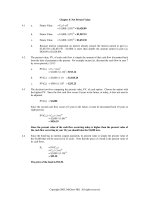
Polarization-changing devices that employ this property are called retarders and are
shown in Fig. 4.2.1. The above example is referred to as a quarter-wave retarder because
the condition
φ = π/2 may be written as (n
1
−n
2
)l = λ/4.
134 4. Propagation in Birefringent Media
Fig. 4.2.1 Linearly and circularly birefringent retarders.
4.3 Chiral Media
Ever since the first experimental observations of optical activity by Arago and Biot in
the early 1800s and Fresnel’s explanation that optical rotation is due to circular bire-
fringence, there have been many attempts to explain it at the molecular level. Pasteur
was the first to postulate that optical activity is caused by the chirality of molecules.
There exist several versions of constitutive relationships that lead to circular bire-
fringence [703–719]. For single-frequency waves, they are all equivalent to each other.
For our purposes, the following so-called Tellegen form is the most convenient [33]:
D = E
−jχH
B
= μH + jχE
(chiral media) (4.3.1)
where
χ is a parameter describing the chirality properties of the medium.
It can be shown that the reality (for a lossless medium) and positivity of the energy
density function
(E
∗
·D + H
∗
·B)/2 requires that the constitutive matrix
−jχ
jχ μ
be hermitian and positive definite. This implies that , μ, χ are real, and furthermore,
that
|χ| <
√
μ. Using Eqs. (4.3.1) in Maxwell’s equations (4.1.5), we obtain:
∂
z
E
±
=∓ωB
±
=∓ω(μH
±
+jχE
±
)
∂
z
H
±
=±ωD
±
=±ω(E
±
−jχH
±
)
(4.3.2)
Defining
c = 1/
√
μ, η =
μ/, k = ω/c = ω
√
μ, and the following real-valued
dimensionless parameter
a = cχ = χ/
√
μ
(so that |a| < 1), we may rewrite Eqs. (4.3.2)
4.3. Chiral Media 135
in the following matrix forms:
∂
∂z
E
±
ηH
±
=∓
jka k
−kjka
E
±
ηH
±
(4.3.3)
These matrix equations may be diagonalized by appropriate linear combinations. For
example, we define the right-polarized (forward-moving) and left-polarized (backward-
moving) waves for the
{E
+
,H
+
} case:
E
R+
=
1
2
E
+
−jηH
+
E
L+
=
1
2
E
+
+jηH
+
E
+
= E
R+
+E
L+
H
+
=−
1
jη
E
R+
−E
L+
(4.3.4)
It then follows from Eq. (4.3.3) that
{E
R+
,E
L+
} will satisfy the decoupled equations:
∂
∂z
E
R+
E
L+
=
−jk
+
0
0
jk
−
E
R+
E
L+
⇒
E
R+
(z)= A
+
e
−jk
+
z
E
L+
(z)= B
+
e
jk
−
z
(4.3.5)
where
k
+
,k
−
are defined as follows:
k
±
= k(1 ± a)= ω
√
μ ± χ
(4.3.6)
We may also define circular refractive indices by
n
±
= k
±
/k
0
, where k
0
is the free-
space wavenumber,
k
0
= ω
√
μ
0
0
. Setting also n = k/k
0
=
√
μ/
√
μ
0
0
, we have:
k
±
= n
±
k
0
,n
±
= n(1 ± a)
(4.3.7)
For the
{E
−
,H
−
}circular components, we define the left-polarized (forward-moving)
and right-polarized (backward-moving) fields by:
E
L−
=
1
2
E
−
+jηH
−
E
R−
=
1
2
E
−
−jηH
−
E
−
= E
L−
+E
R−
H
−
=
1
jη
E
L−
−E
R−
(4.3.8)
Then, {E
L−
,E
R−
} will satisfy:
∂
∂z
E
L−
E
R−
=
−jk
−
0
0
jk
+
E
L−
E
R−
⇒
E
L−
(z)= A
−
e
−jk
−
z
E
R−
(z)= B
−
e
jk
+
z
(4.3.9)
In summary, we obtain the complete circular-basis fields
E
±
(z):
E
+
(z) = E
R+
(z)+E
L+
(z)= A
+
e
−jk
+
z
+B
+
e
jk
−
z
E
−
(z) = E
L−
(z)+E
R−
(z)= A
−
e
−jk
−
z
+B
−
e
jk
+
z
(4.3.10)
Thus, the
E
+
(z) circular component propagates forward with wavenumber k
+
and
backward with
k
−
, and the reverse is true of the E
−
(z) component. The forward-moving
component of
E
+
and the backward-moving component of E
−
, that is, E
R+
and E
R−
, are
136 4. Propagation in Birefringent Media
both right-polarized and both propagate with the same wavenumber
k
+
. Similarly, the
left-polarized waves
E
L+
and E
L−
both propagate with k
−
.
Thus, a wave of given circular polarization (left or right) propagates with the same
wavenumber regardless of its direction of propagation. This is a characteristic difference
of chiral versus gyrotropic media in external magnetic fields.
Consider, next, the effect of natural rotation. We start with a linearly polarized field
at
z = 0 and decompose it into its circular components:
E
(0)=
ˆ
x A
x
+
ˆ
y A
y
=
ˆ
e
+
A
+
+
ˆ
e
−
A
−
, with A
±
=
1
2
(A
x
±jA
y
)
where A
x
,A
y
must be real for linear polarization. Propagating the circular components
forward by a distance
l according to Eq. (4.3.10), we find:
E
(l) =
ˆ
e
+
A
+
e
−jk
+
l
+
ˆ
e
−
A
−
e
−jk
−
l
=
ˆ
e
+
A
+
e
−j(k
+
−k
−
)l/2
+
ˆ
e
−
A
−
e
j(k
+
−k
−
)l/2
e
−j(k
+
+k
−
)l/2
=
ˆ
e
+
A
+
e
−jφ
+
ˆ
e
−
A
−
e
jφ
e
−j(k
+
+k
−
)l/2
(4.3.11)
where we defined the angle of rotation:
φ =
1
2
(k
+
−k
−
)l = akl (natural rotation) (4.3.12)
Going back to the linear basis, we find:
ˆ
e
+
A
+
e
−jφ
+
ˆ
e
−
A
−
e
jφ
= (
ˆ
x − j
ˆ
y)
1
2
(A
x
+jA
y
)e
−jφ
+(
ˆ
x + j
ˆ
y)
1
2
(A
x
−jA
y
)e
jφ
=
ˆ
x cos φ −
ˆ
y sin φ
A
x
+
ˆ
y cos φ +
ˆ
x sin φ
A
y
=
ˆ
x
A
x
+
ˆ
y
A
y
Therefore, at z = 0 and z = l, we have:
E
(0)=
ˆ
x A
x
+
ˆ
y A
y
E(l) =
ˆ
x
A
x
+
ˆ
y
A
y
e
−j(k
+
+k
−
)l/2
(4.3.13)
The new unit vectors
ˆ
x
=
ˆ
x cos
φ−
ˆ
y sin
φ and
ˆ
y
=
ˆ
y cos
φ+
ˆ
x sin
φ are recognized
as the unit vectors
ˆ
x
,
ˆ
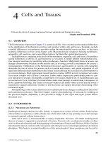
y rotated clockwise (if φ>0) by the angle φ, as shown in Fig. 4.2.1
(for the case
A
x
= 0, A
y
= 0.) Thus, the wave remains linearly polarized, but its
polarization plane rotates as it propagates.
If the propagation is in the negative
z-direction, then as follows from Eq. (4.3.10), the
roles of
k
+
and k
−
are interchanged so that the rotation angle becomes φ = (k
−
−k
+
)l/2,
which is the negative of that of Eq. (4.3.12).
If a linearly polarized wave travels forward by a distance
l, gets reflected, and travels
back to the starting point, the total angle of rotation will be zero. By contrast, in the
Faraday rotation case, the angle keeps increasing so that it doubles after a round trip
(see Problem 4.10.)
4.4. Gyrotropic Media 137
4.4 Gyrotropic Media
Gyrotropic
†
media are isotropic media in the presence of constant external magnetic
fields. A gyroelectric medium (at frequency
ω) has constitutive relationships:
⎡
⎢
⎣
D
x
D
y
D
z
⎤
⎥
⎦
=
⎡
⎢
⎣
1
j
2
0
−j
2
1
0
00
3
⎤
⎥
⎦
⎡
⎢
⎣
E
x
E
y
E
z
⎤
⎥
⎦
,
B = μH (4.4.1)
For a lossless medium, the positivity of the energy density function requires that the
permittivity matrix be hermitian and positive-definite, which implies that
1
,
2
,
3
are
real, and moreover,
1
> 0, |
2
|≤
1
, and
3
> 0. The quantity
2
is proportional to the
external magnetic field and reverses sign with the direction of that field.
A gyromagnetic medium, such as a ferrite in the presence of a magnetic field, has
similar constitutive relationships, but with the roles of D and H interchanged:
⎡
⎢
⎣
B
x
B
y
B
z
⎤
⎥
⎦
=
⎡
⎢
⎣
μ
1
jμ
2
0
−jμ
2
μ
1
0
00
μ
3
⎤
⎥
⎦
⎡
⎢
⎣
H
x
H
y
H
z
⎤
⎥
⎦
,
D = E (4.4.2)
where again
μ
1
> 0, |μ
2
|≤μ
1
, and μ
3
> 0 for a lossless medium.
In the circular basis of Eq. (4.1.1), the above gyrotropic constitutive relationships
take the simplified forms:
D
±
= (
1
±
2
)E
±
,B
±
= μH
±
,
(gyroelectric)
B
±
= (μ
1
±μ
2
)H
±
,D
±
= E
±
, (gyromagnetic)
(4.4.3)
where we ignored the
z-components, which are zero for a uniform plane wave propa-
gating in the
z-direction. For example,
D
x
±jD
y
= (
1
E
x
+j
2
E
y
)±j(
1
E
y
−j
2
E
x
)= (
1
±
2
)(E
x
±jE
y
)
Next, we solve Eqs. (4.1.5) for the forward and backward circular-basis waves. Con-
sidering the gyroelectric case first, we define the following quantities:
±
=
1
±
2
,k
±
= ω
√
μ
±
,η
±
=
μ
±
(4.4.4)
Using these definitions and the constitutive relations
D
±
=
±
E
±
, Eqs. (4.1.5) may
be rearranged into the following matrix forms:
∂
∂z
E
±
η
±
H
±
=
0
∓k
±
±k
±
0
E
±
η
±
H
±
(4.4.5)
These may be decoupled by defining forward- and backward-moving fields as in
Eqs. (4.3.4) and (4.3.8), but using the corresponding circular impedances
η
±
:
E
R+
=
1
2
E
+
−jη
+
H
+
E
L+
=
1
2
E
+
+jη
+
H
+
E
L−
=
1
2
E
−
+jη
−
H
−
E
R−
=
1
2
E
−
−jη
−
H
−
(4.4.6)
†
The term “gyrotropic” is sometimes also used to mean “optically active.”
138 4. Propagation in Birefringent Media
These satisfy the decoupled equations:
∂
∂z
E
R+
E
L+
=
−jk
+
0
0
jk
+
E
R+
E
L+
⇒
E
R+
(z)= A
+
e
−jk
+
z
E
L+
(z)= B
+
e
jk
+
z
∂
∂z
E
L−
E
R−
=
−jk
−
0
0
jk
−
E
L−
E
R−
⇒
E
L−
(z)= A
−
e
−jk
−
z
E
R−
(z)= B
−
e
jk
−
z
(4.4.7)
Thus, the complete circular-basis fields
E
±
(z) are:
E
+
(z) = E
R+
(z)+E
L+
(z)= A
+
e
−jk
+
z
+B
+
e
jk
+
z
E
−
(z) = E
L−
(z)+E
R−
(z)= A
−
e
−jk
−
z
+B
−
e
jk
−
z
(4.4.8)
Now, the
E
+
(z) circular component propagates forward and backward with the same
wavenumber
k
+
, while E
−
(z) propagates with k
−
. Eq. (4.3.13) and the steps leading to
it remain valid here. The rotation of the polarization plane is referred to as the Faraday
rotation. If the propagation is in the negative
z-direction, then the roles of k
+
and k
−
remain unchanged so that the rotation angle is still the same as that of Eq. (4.3.12).
If a linearly polarized wave travels forward by a distance
l, gets reflected, and travels
back to the starting point, the total angle of rotation will be double that of the single
trip, that is, 2
φ = (k
+
−k
−
)l.
Problems 1.10 and 4.12 discuss simple models of gyroelectric behavior for conduc-
tors and plasmas in the presence of an external magnetic field. Problem 4.14 develops
the Appleton-Hartree formulas for plane waves propagating in plasmas, such as the
ionosphere [720–724].
The gyromagnetic case is essentially identical to the gyroelectric one. Eqs. (4.4.5) to
(4.4.8) remain the same, but with circular wavenumbers and impedances defined by:
μ
±
= μ
1
±μ
2
,k
±
= ω
√
μ
±
,η
±
=
μ
±
(4.4.9)
Problem 4.13 discusses a model for magnetic resonance exhibiting gyromagnetic
behavior. Magnetic resonance has many applications—from NMR imaging to ferrite mi-
crowave devices [725–736]. Historical overviews may be found in [734,736].
4.5 Linear and Circular Dichroism
Dichroic polarizers, such as polaroids, are linearly birefringent materials that have widely
different attenuation coefficients along the two polarization directions. For a lossy ma-
terial, the field solutions given in Eq. (4.2.4) are modified as follows:
E
x
(z)= Ae
−jk
1
z
= Ae
−α
1
z
e
−jβ
1
z
,k
1
= ω
√
μ
1
= β
1
−jα
1
E
y
(z)= Be
−jk
2
z
= Be
−α
2
z
e
−jβ
1
2
,k
2
= ω
√
μ
2
= β
2
−jα
2
(4.5.1)
where
α
1
,α
2
are the attenuation coefficients. Passing through a length l of such a
material, the initial and output polarizations will be as follows:
4.6. Oblique Propagation in Birefringent Media 139
E
(0)=
ˆ
x A +
ˆ
y B
E(l) =
ˆ
x Ae
−jk
1
l
+
ˆ
y Be
−jk
2
l
=
ˆ
x Ae
−α
1
l
+
ˆ
y Be
−α
2
l
e
jφ
e
−jβ
1
l
(4.5.2)
In addition to the phase change
φ = (β
1
−β
2
)l, the field amplitudes have attenuated
by the unequal factors
a
1
= e
−α
1
l
and a
2
= e
−α
2
l
. The resulting polarization will be
elliptic with unequal semi-axes. If
α
2
α
1
, then a
2
a
1
and the y-component can be
ignored in favor of the
x-component.
This is the basic principle by which a polaroid material lets through only a preferred
linear polarization. An ideal linear polarizer would have
a
1
= 1 and a
2
= 0, correspond-
ing to
α
1
= 0 and α
2
=∞. Typical values of the attenuations for commercially available
polaroids are of the order of
a
1
= 0.9 and a
2
= 10
−2
,or0.9 dB and 40 dB, respectively.
Chiral media may exhibit circular dichroism [705,718], in which the circular wavenum-
bers become complex,
k
±
= β
±
−jα
±
. Eq. (4.3.11) reads now:
E
(l) =
ˆ
e
+
A
+
e
−jk
+
l
+
ˆ
e
−
A
−
e
−jk
−
l
=
ˆ
e
+
A
+
e
−j(k
+
−k
−
)l/2
+
ˆ
e
−
A
−
e
j(k
+
−k
−
)l/2
e
−j(k
+
+k
−
)l/2
=
ˆ
e
+
A
+
e
−ψ−jφ
+
ˆ
e
−
A
−
e
ψ+jφ
e
−j(k
+
+k
−
)l/2
(4.5.3)
where we defined the complex rotation angle:
φ − jψ =
1
2
(k
+
−k
−
)l =
1
2
(β
+
−β
−
)l − j
1
2
(α
+
−α
−
)l (4.5.4)
Going back to the linear basis as in Eq. (4.3.13), we obtain:
E
(0)=
ˆ
x A
x
+
ˆ
y A
y
E(l) =
ˆ
x
A
x
+
ˆ
y
A
y
e
−j(k
+
+k
−
)l/2
(4.5.5)
where
{
ˆ
x
,
ˆ
y
} are the same rotated (by φ) unit vectors of Eq. (4.3.13), and
A
x
= A
x
cosh ψ −jA
y
sinh ψ
A
y
= A
y
cosh ψ +jA
x
sinh ψ
(4.5.6)
Because the amplitudes
A
x
,A
y
are now complex-valued, the resulting polarization
will be elliptical.
4.6 Oblique Propagation in Birefringent Media
Here, we discuss TE and TM waves propagating in oblique directions in linearly birefrin-
gent media. We will use these results in Chap. 8 to discuss reflection and refraction in
such media, and to characterize the properties of birefringent multilayer structures.
Applications include the recently manufactured (by 3M, Inc.) multilayer birefrin-
gent polymer mirrors that have remarkable and unusual optical properties, collectively
referred to as giant birefringent optics (GBO) [681].
Oblique propagation in chiral and gyrotropic media is discussed in the problems.
Further discussions of wave propagation in anisotropic media may be found in [30–32].
140 4. Propagation in Birefringent Media
We recall from Sec. 2.9 that a uniform plane wave propagating in a lossless isotropic
dielectric in the direction of a wave vector k is given by:
E
(r)= E e
−j k·r
, H(r)= H e
−j k·r
, with
ˆ
k · E = 0 , H =
n
η
0
ˆ
k
×E (4.6.1)
where n is the refractive index of the medium n =
/
0
, η
0
the free-space impedance,
and
ˆ
k the unit-vector in the direction of k, so that,
k
= k
ˆ
k
,k=|k|=ω
√
μ
0
= nk
0
,k
0
=
ω
c
0
= ω
√
μ
0
0
(4.6.2)
and
k
0
is the free-space wavenumber. Thus, E, H,
ˆ
k form a right-handed system.
In particular, following the notation of Fig. 2.9.1, if k is chosen to lie in the
xz plane
at an angle
θ from the z-axis, that is,
ˆ
k =
ˆ
x sin θ +
ˆ
z cos θ, then there will be two inde-
pendent polarization solutions: TM, parallel, or p-polarization, and TE, perpendicular,
or s-polarization, with fields given by
(TM, p-polarization): E
= E
0
(
ˆ
x cos
θ −
ˆ
z sin
θ) , H =
n
η
0
E
0
ˆ
y
(TE, s-polarization): E
= E
0
ˆ
y
, H =
n
η
0
E
0
(−
ˆ
x cos
θ +
ˆ
z sin
θ)
(4.6.3)
where, in both the TE and TM cases, the propagation phase factor
e
−j k
·r
is:
e
−j k·r
= e
−j(k
z
z+k
x
x)
= e
−jk
0
n(z cos θ+x sin θ)
(4.6.4)
The designation as parallel or perpendicular is completely arbitrary here and is taken
with respect to the
xz plane. In the reflection and refraction problems discussed in
Chap. 7, the dielectric interface is taken to be the
xy plane and the xz plane becomes
the plane of incidence.
In a birefringent medium, the propagation of a uniform plane wave with arbitrary
wave vector k is much more difficult to describe. For example, the direction of the
Poynting vector is not towards k, the electric field E is not orthogonal to k, the simple
dispersion relationship
k = nω/c
0
is not valid, and so on.
In the previous section, we considered the special case of propagation along an ordi-
nary optic axis in a birefringent medium. Here, we discuss the somewhat more general
case in which the
xyz coordinate axes coincide with the principal dielectric axes (so that
the permittivity tensor is diagonal,) and we take the wave vector k to lie in the
xz plane
at an angle
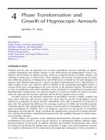
θ from the z-axis. The geometry is depicted in Fig. 4.6.1.
Although this case is still not the most general one with a completely arbitrary direc-
tion for k, it does contain most of the essential features of propagation in birefringent
media. The 3M multilayer films mentioned above have similar orientations for their
optic axes [681].
The constitutive relations are assumed to be B
= μ
0
H and a diagonal permittivity
tensor for D. Let
1
,
2
,
3
be the permittivity values along the three principal axes and
define the corresponding refractive indices
n
i
=
i
/
0
, i = 1, 2, 3. Then, the D -E
relationship becomes:
⎡
⎢
⎣
D
x
D
y
D
z
⎤
⎥
⎦
=
⎡
⎢
⎣
1
00
0
2
0
00
3
⎤
⎥
⎦
⎡
⎢
⎣
E
x
E
y
E
z
⎤
⎥
⎦
=
0
⎡
⎢
⎣
n
2
1
00
0
n
2
2
0
00
n
2
3
⎤
⎥
⎦
⎡
⎢
⎣
E
x
E
y
E
z
⎤
⎥
⎦
(4.6.5)
4.6. Oblique Propagation in Birefringent Media 141
Fig. 4.6.1 Uniform plane waves in a birefringent medium.
For a biaxial medium, the three n
i
are all different. For a uniaxial medium, we take
the
xy-axes to be ordinary, with n
1
= n
2
= n
o
, and the z-axis to be extraordinary, with
n
3
= n
e
.
†
The wave vector k can be resolved along the z and x directions as follows:
k
= k
ˆ
k
= k(
ˆ
x sin θ +
ˆ
z cos θ)=
ˆ
xk
x
+
ˆ
zk
z
(4.6.6)
The
ω-k relationship is determined from the solution of Maxwell’s equations. By
analogy with the isotropic case that has
k = nk
0
= nω/c
0
, we may define an effective
refractive index
N such that:
k = Nk
0
= N
ω
c
0
(effective refractive index) (4.6.7)
We will see in Eq. (4.6.22) by solving Maxwell’s equations that
N depends on the
chosen polarization (according to Fig. 4.6.1) and on the wave vector direction
θ:
N =
⎧
⎪
⎪
⎨
⎪
⎪
⎩
n
1
n
3
n
2
1
sin
2
θ + n
2
3
cos
2
θ
,
(TM, p-polarization)
n
2
, (TE, s-polarization)
(4.6.8)
For the TM case, we may rewrite the
N-θ relationship in the form:
1
N
2
=
cos
2
θ
n
2
1
+
sin
2
θ
n
2
3
(effective TM index) (4.6.9)
Multiplying by
k
2
and using k
0
= k/N, and k
x
= k sin θ, k
z
= k cos θ, we obtain the
ω-k relationship for the TM case:
ω
2
c
2
0
=
k
2
z
n
2
1
+
k
2
x
n
2
3
(TM, p-polarization) (4.6.10)
Similarly, we have for the TE case:
ω
2
c
2
0
=
k
2
n
2
2
(TE, s-polarization) (4.6.11)
†
In Sec. 4.2, the extraordinary axis was the x-axis.
142 4. Propagation in Birefringent Media
Thus, the TE mode propagates as if the medium were isotropic with index
n = n
2
,
whereas the TM mode propagates in a more complicated fashion. If the wave vector k
is along the ordinary
x-axis (θ = 90
o
), then k = k
x
= n
3
ω/c
0
(this was the result of
the previous section), and if k is along the extraordinary
z-axis (θ = 0
o
), then we have
k = k
z
= n
1
ω/c
0
.
For TM modes, the group velocity is not along k. In general, the group velocity
depends on the
ω-k relationship and is computed as v = ∂ω/∂k. From Eq. (4.6.10), we
find the
x- and z-components:
v
x
=
∂ω
∂k
x
=
k
x
c
2
0
ωn
2
3
= c
0
N
n
2
3
sin θ
v
z
=
∂ω
∂k
z
=
k
z
c
2
0
ωn
2
1
= c
0
N
n
2
1
cos θ
(4.6.12)
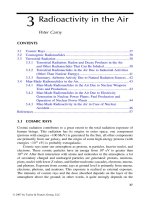
The velocity vector v is not parallel to k. The angle
¯
θ that v forms with the z-axis is
given by tan
¯
θ = v
x
/v
z
. It follows from (4.6.12) that:
tan
¯
θ =
n
2
1
n
2
3
tan θ
(group velocity direction) (4.6.13)
Clearly,
¯
θ = θ if n
1
= n
3
. The relative directions of k and v are shown in Fig. 4.6.2.
The group velocity is also equal to the energy transport velocity defined in terms of the
Poynting vector
P
P
P
and energy density w as v =P
P
P/w. Thus, v and
P
P
P have the same
direction. Moreover, with the electric field being orthogonal to the Poynting vector, the
angle
¯
θ
is also equal to the angle the E-field forms with the x-axis.
Fig. 4.6.2 Directions of group velocity, Poynting vector, wave vector, and electric field.
Next, we derive Eqs. (4.6.8) for N and solve for the field components in the TM
and TE cases. We look for propagating solutions of Maxwell’s equations of the type
E
(r)= E
e
−j k·r
and H(r)= H e
−j k·r
. Replacing the gradient operator by ∇
∇
∇→−jk and
canceling some factors of
j, Maxwell’s equations take the form:
4.6. Oblique Propagation in Birefringent Media 143
∇
∇
∇×
E =−jωμ
0
H
∇
∇
∇×
H = jωD
∇
∇
∇·D = 0
∇
∇
∇·H = 0
⇒
k
×E = ωμ
0
H
k
×H =−ωD
k
·D = 0
k
·H = 0
(4.6.14)
The last two equations are implied by the first two, as can be seen by dotting both
sides of the first two with k. Replacing k
= k
ˆ
k
= Nk
0
ˆ
k, where
N is still to be determined,
we may solve Faraday’s law for H in terms of E :
N
ω
c
0
ˆ
k
×E = ωμ
0
H ⇒ H =
N
η
0
ˆ
k
×E
(4.6.15)
where we used
η
0
= c
0
μ
0
. Then, Amp
`
ere’s law gives:
D
=−
1
ω
k
×H =−
1
ω
N
ω
c
0
ˆ
k
×H =
N
2
η
0
c
0
ˆ
k
×(E ×
ˆ
k
) ⇒
ˆ
k
×(E ×
ˆ
k
)=
1
0
N
2
D
where we used c
0
η
0
= 1/
0
. The quantity
ˆ
k×(E ×
ˆ
k
) is recognized as the component of
E that is transverse to the propagation unit vector
ˆ
k. Using the BAC-CAB vector identity,
we have
ˆ
k
×(E ×
ˆ
k
)= E −
ˆ
k
(
ˆ
k
·E). Rearranging terms, we obtain:
E −
1
0
N
2
D =
ˆ
k
(
ˆ
k
·E) (4.6.16)
Because D is linear in E, this is a homogeneous linear equation. Therefore, in order
to have a nonzero solution, its determinant must be zero. This provides a condition
from which
N can be determined.
To obtain both the TE and TM solutions, we assume initially that E has all its three
components and rewrite Eq. (4.6.16) component-wise. Using Eq. (4.6.5) and noting that
ˆ
k
·E = E
x
sin θ +E
z
cos θ, we obtain the homogeneous linear system:
1 −
n
2
1
N
2
E
x
= (E
x
sin θ +E
z
cos θ)sin θ
1 −
n
2
2
N
2
E
y
= 0
1 −
n
2
3
N
2
E
z
= (E
x
sin θ +E
z
cos θ)cos θ
(4.6.17)
The TE case has
E
y
= 0 and E
x
= E
z
= 0, whereas the TM case has E
x
= 0, E
z
= 0,
and
E
y
= 0. Thus, the two cases decouple.
In the TE case, the second of Eqs. (4.6.17) immediately implies that
N = n
2
. Setting
E
= E
0
ˆ
y and using
ˆ
k ×
ˆ
y =−
ˆ
x cos θ +
ˆ
z sin θ, we obtain the TE solution:
144 4. Propagation in Birefringent Media
E(r) = E
0
ˆ
y
e
−j k·r
H(r) =
n
2
η
0
E
0
(−
ˆ
x cos θ +
ˆ
z sin θ)e
−j k·r
(TE) (4.6.18)
where the TE propagation phase factor is:
e
−j k·r
= e
−jk
0
n
2
(z cos θ+x sin θ)
(TE propagation factor) (4.6.19)
The TM case requires a little more work. The linear system (4.6.17) becomes now:
1 −
n
2
1
N
2
E
x
= (E
x
sin θ +E
z
cos θ)sin θ
1 −
n
2
3
N
2
E
z
= (E
x
sin θ +E
z
cos θ)cos θ
(4.6.20)
Using the identity sin
2
θ + cos
2
θ = 1, we may rewrite Eq. (4.6.20) in the matrix form:
⎡
⎢
⎢
⎣
cos
2
θ −
n
2
1
N
2
−sin θ cos θ
−
sin
θ cos θ sin
2
θ −
n
2
3
N
2
⎤
⎥
⎥
⎦
E
x
E
z
=
0 (4.6.21)
Setting the determinant of the coefficient matrix to zero, we obtain the desired con-
dition on
N in order that a non-zero solution E
x
,E
z
exist:
cos
2
θ −
n
2
1
N
2
sin
2
θ −
n
2
3
N
2
−
sin
2
θ cos
2
θ = 0 (4.6.22)
This can be solved for
N
2
to give Eq. (4.6.9). From it, we may also derive the following
relationship, which will prove useful in applying Snel’s law in birefringent media:
N cos θ =
n
1
n
3
n
2
3
−N
2
sin
2
θ = n
1
1 −
N
2
sin
2
θ
n
2
3
(4.6.23)
With the help of the relationships given in Problem 4.16, the solution of the homo-
geneous system (4.6.20) is found to be, up to a proportionality constant:
E
x
= A
n
3
n
1
cos θ, E
z
=−A
n
1
n
3
sin θ (4.6.24)
The constant
A can be expressed in terms of the total magnitude of the field E
0
=
|
E
|=
|E
x
|
2
+|E
z
|
2
. Using the relationship (4.7.11), we find (assuming A>0):
A = E
0
N
n
2
1
+n
2
3
−N
2
(4.6.25)
The magnetic field H can also be expressed in terms of the constant
A. We have:
4.6. Oblique Propagation in Birefringent Media 145
H
=
N
η
0
ˆ
k
×E =
N
η
0
(
ˆ
x sin θ +
ˆ
z cos θ)×(
ˆ
xE
x
+
ˆ
zE
z
)
=
N
η
0
ˆ
y(E
x
cos θ −E
z
sin θ)=
N
η
0
ˆ
y A
n
3
n
1
cos
2
θ +
n
1
n
3
sin
2
θ
=
N
η
0
ˆ
y
A
n
1
n
3
N
2
=
A
η
0
ˆ
y
n
1
n
3
N
(4.6.26)
where we used Eq. (4.7.10). In summary, the complete TM solution is:
E(r) = E
0
N
n
2
1
+n
2
3
−N
2
ˆ
x
n
3
n
1
cos θ −
ˆ
z
n
1
n
3
sin θ
e
−j k·r
H
(r) =
E
0
η
0
n
1
n
3
n
2
1
+n
2
3
−N
2
ˆ
y e
−j k·r
(TM) (4.6.27)
where the TM propagation phase factor is:
e
−j k·r
= e
−jk
0
N(zcos θ+x sin θ)
(TM propagation factor) (4.6.28)
The solution has been put in a form that exhibits the proper limits at
θ = 0
o
and
90
o
. It agrees with Eq. (4.6.3) in the isotropic case. The angle that E forms with the x-axis
in Fig. 4.6.2 is given by tan
¯
θ =−E
z
/E
x
and agrees with Eq. (4.6.13).
Next, we derive expressions for the Poynting vector and energy densities. It turns
out—as is common in propagation and waveguide problems—that the magnetic energy
density is equal to the electric one. Using Eq. (4.6.27), we find:
P
P
P=
1
2
Re
(E × H
∗
)=
E
2
0
2η
0
n
1
n
3
N
n
2
1
+n
2
3
−N
2
ˆ
x
n
1
n
3
sin θ +
ˆ
z
n
3
n
1
cos θ
(4.6.29)
and for the electric, magnetic, and total energy densities:
w
e
=
1
2
Re
(D · E
∗
)=
1
4
0
n
2
1
|E
x
|
2
+n
2
3
|E
z
|
2
=
1
4
0
E
2
0
n
2
1
n
2
3
n
2
1
+n
2
3
−N
2
w
m
=
1
2
Re
(B · H
∗
)=
1
4
μ
0
|H
y
|
2
=
1
4
0
E
2
0
n
2
1
n
2
3
n
2
1
+n
2
3
−N
2
= w
e
w = w
e
+w
m
= 2w
e
=
1
2
0
E
2
0
n
2
1
n
2
3
n
2
1
+n
2
3
−N
2
(4.6.30)
The vector
P
P
P is orthogonal to E and its direction is
¯
θ given by Eq. (4.6.13), as can be
verified by taking the ratio tan
¯
θ =P
x
/P
z
. The energy transport velocity is the ratio of
the energy flux to the energy density—it agrees with the group velocity (4.6.12):
v
=
P
P
P
w
= c
0
ˆ
x
N
n
2
3
sin θ +
ˆ
z
N
n
2
1
cos θ
(4.6.31)
To summarize, the TE and TM uniform plane wave solutions are given by Eqs. (4.6.18)
and (4.6.27). We will use these results in Sects. 8.10 and 8.12 to discuss reflection and re-
fraction in birefringent media and multilayer birefringent dielectric structures. Further
discussion of propagation in birefringent media can be found in [621,57] and [681–702].
146 4. Propagation in Birefringent Media
4.7 Problems
4.1 For the circular-polarization basis of Eq. (4.1.1), show
E
=
ˆ
e
+
E
+
+
ˆ
e
−
E
−
⇒
ˆ
z
×E = j
ˆ
e
+
E
+
−j
ˆ
e
−
E
−
⇒
ˆ
z
×E
±
=±jE
±
4.2 Show the component-wise Maxwell equations, Eqs. (4.1.4) and (4.1.5), with respect to the
linear and circular polarization bases.
4.3 Suppose that the two unit vectors
{
ˆ
x
,
ˆ
y
} are rotated about the z-axis by an angle φ resulting
in
ˆ
x
=
ˆ
x cos
φ +
ˆ
y sin
φ and
ˆ
y
=
ˆ
y cos
φ −
ˆ
x sin
φ. Show that the corresponding circular
basis vectors
ˆ
e
±
=
ˆ
x
∓j
ˆ
y and
ˆ
e
±
=
ˆ
x
∓j
ˆ
y
change by the phase factors:
ˆ
e
±
= e
±jφ
ˆ
e
±
.
4.4 Consider a linearly birefringent 90
o
quarter-wave retarder. Show that the following input
polarizations change into the indicated output ones:
ˆ
x
±
ˆ
y
→
ˆ
x
±j
ˆ
y
ˆ
x
±j
ˆ
y
→
ˆ
x
±
ˆ
y
What are the output polarizations if the same input polarizations go through a 180
o
half-
wave retarder?
4.5 A polarizer lets through linearly polarized light in the direction of the unit vector
ˆ
e
p
=
ˆ
x cos
θ
p
+
ˆ
y sin
θ
p
, as shown in Fig. 4.7.1. The output of the polarizer propagates in the
z-direction through a linearly birefringent retarder of length l, with birefringent refractive
indices
n
1
,n
2
, and retardance φ = (n
1
−n
2
)k
0
l.
Fig. 4.7.1 Polarizer-analyzer measurement of birefringence.
The output E
(l) of the birefringent sample goes through an analyzing linear polarizer that
lets through polarizations along the unit vector
ˆ
e
a
=
ˆ
x cos
θ
a
+
ˆ
y sin
θ
a
. Show that the light
intensity at the output of the analyzer is given by:
I
a
=
ˆ
e
a
·E(l)
2
=
cos θ
a
cos θ
p
+e
jφ
sin θ
a
sin θ
p
2
For a circularly birefringent sample that introduces a natural or Faraday rotation of φ =
(k
+
−k
−
)l/2, show that the output light intensity will be:
I
a
=
ˆ
e
a
·E(l)
2
= cos
2
(θ
p
−θ
a
−φ)
For both the linear and circular cases, what are some convenient choices for θ
a
and θ
p
?
4.6 A linearly polarized wave with polarization direction at an angle
θ with the x-axis goes
through a circularly birefringent retarder that introduces an optical rotation by the angle
φ = (k
+
−k
−
)l/2. Show that the input and output polarization directions will be:
ˆ
x cos
θ +
ˆ
y sin
θ →
ˆ
x cos
(θ −φ)+
ˆ
y sin
(θ −φ)
4.7. Problems 147
4.7 Show that an arbitrary polarization vector can be expressed as follows with respect to a
linear basis
{
ˆ
x
,
ˆ
y
} and its rotated version {
ˆ
x
,
ˆ
y
}:
E
= A
ˆ
x
+B
ˆ
y
= A
ˆ
x
+B
ˆ
y
where the new coefficients and the new basis vectors are related to the old ones by a rotation
by an angle
φ:
A
B
=
cos φ sin φ
−
sin φ cos φ
A
B
,
ˆ
x
ˆ
y
=
cos φ sin φ
−
sin φ cos φ
ˆ
x
ˆ
y
4.8 Show that the source-free Maxwell’s equations (4.1.2) for a chiral medium characterized by
(4.3.1), may be cast in the matrix form, where
k = ω
√
μ, η =
μ/, and a = χ/
√
μ:
∇
∇
∇×
E
ηH
=
ka −jk
jk ka
E
ηH
Show that these may be decoupled by forming the “right” and “left” polarized fields:
∇
∇
∇×
E
R
E
L
=
k
+
0
0
−k
−
E
R
E
L
,
where E
R
=
1
2
(E −jηH), E
L
=
1
2
(E +jηH)
where k
±
= k(1 ± a). Using these results, show that the possible plane-wave solutions
propagating in the direction of a unit-vector
ˆ
k are given by:
E
(r)= E
0
(
ˆ
p
−j
ˆ
s
)e
−j k
+
·r
and E(r)= E
0
(
ˆ
p
+j
ˆ
s
)e
−j k
−
·r
where k
±
= k
±
ˆ
k and
{
ˆ
p
,
ˆ
s
,
ˆ
k
} form a right-handed system of unit vectors, such as {
ˆ
x
,
ˆ
y
,
ˆ
z
}
of Fig. 2.9.1. Determine expressions for the corresponding magnetic fields. What freedom
do we have in selecting
{
ˆ
p
,
ˆ
s
} for a given direction
ˆ
k ?
4.9 Using Maxwell’s equations (4.1.2), show the following Poynting-vector relationships for an
arbitrary source-free medium:
∇
∇
∇·
E ×H
∗
= jω
D
∗
·E −B · H
∗
∇
∇
∇·
Re
E ×H
∗
=−ω Im
D
∗
·E +B
∗
·H
Explain why a lossless medium must satisfy the condition ∇
∇
∇·Re
E × H
∗
=
0. Show that
this condition requires that the energy function
w = (D
∗
·E +B
∗
·H)/2 be real-valued.
For a lossless chiral medium characterized by (4.3.1), show that the parameters , μ, χ are
required to be real. Moreover, show that the positivity of the energy function
w>0 requires
that
|χ| <
√
μ, as well as >0 and μ>0.
4.10 In a chiral medium, at
z = 0 we lauch the fields E
R+
(0) and E
L−
(0), which propagate by a
distance
l, get reflected, and come back to the starting point. Assume that at the point of
reversal the fields remain unchanged, that is,
E
R+
(l)= E
L+
(l) and E
L−
(l)= E
R−
(l). Using
the propagation results (4.3.5) and (4.3.9), show that fields returned back at
z = 0 will be:
E
L+
(0)= E
L+
(l)e
−jk
−
l
= E
R+
(l)e
−jk
−
l
= E
R+
(0)e
−j(k
+
+k
−
)l
E
R−
(0)= E
R−
(l)e
−jk
+
l
= E
L−
(l)e
−jk
+
l
= E
L−
(0)e
−j(k
+
+k
−
)l
Show that the overall natural rotation angle will be zero. For a gyrotropic medium, show
that the corresponding rountrip fields will be:
148 4. Propagation in Birefringent Media
E
L+
(0)= E
L+
(l)e
−jk
−
l
= E
R+
(l)e
−jk
−
l
= E
R+
(0)e
−2jk
+
l
E
R−
(0)= E
R−
(l)e
−jk
+
l
= E
L−
(l)e
−jk
+
l
= E
L−
(0)e
−2jk
−
l
Show that the total Faraday rotation angle will be 2φ = (k
+
−k
−
)l.
4.11 Show that the
x, y components of the gyroelectric and gyromagnetic constitutive relation-
ships (4.4.1) and (4.4.2) may be written in the compact forms:
D
T
=
1
E
T
−j
2
ˆ
z
×E
T
(gyroelectric)
B
T
= μ
1
H
T
−jμ
2
ˆ
z
×H
T
(gyromagnetic)
where the subscript
T indicates the transverse (with respect to z) part of a vector, for exam-
ple, D
T
=
ˆ
x
D
x
+
ˆ
y
D
y
.
4.12 Conductors and plasmas exhibit gyroelectric behavior when they are in the presence of an
external magnetic field. The equation of motion of conduction electrons in a constant mag-
netic field is
m
˙
v
= e(E + v × B)−mαv, with the collisional damping term included. The
magnetic field is in the
z-direction, B =
ˆ
z
B
0
.
Assuming
e
jωt
time dependence and decomposing all vectors in the circular basis (4.1.1),
for example, v
=
ˆ
e
+
v
+
+
ˆ
e
−
v
−
+
ˆ
z
v
z
, show that the solution of the equation of motion is:
v
±
=
e
m
E
±
α +j(ω ±ω
B
)
,v
z
=
e
m
E
z
α +jω
where ω
B
= eB
0
/m is the cyclotron frequency. Then, show that the D−E constitutive
relationship takes the form of Eq. (4.4.1) with:
±
=
1
±
2
=
0
1 −
jω
2
p
ω
α +j(ω ±ω
B
)
,
3
=
0
1 −
jω
2
p
ω(α +jω)
where ω
2
p
= Ne
2
/m
0
is the plasma frequency and N, the number of conduction electrons
per unit volume. (See Problem 1.10 for some helpful hints.)
4.13 If the magnetic field H
tot
=
ˆ
z
H
0
+ He
jωt
is applied to a magnetizable sample, the in-
duced magnetic moment per unit volume (the magnetization) will have the form M
tot
=
ˆ
z
M
0
+ Me
jωt
, where
ˆ
z M
0
is the saturation magnetization due to
ˆ
z H
0
acting alone. The
phenomenological equations governing M
tot
, including a so-called Landau-Lifshitz damping
term, are given by [733]:
dM
tot
dt
= γ(M
tot
×H
tot
)−
α
M
0
H
0
M
tot
×(M
tot
×H
tot
)
where γ is the gyromagnetic ratio and τ = 1/α, a relaxation time constant. Assuming that
|H|H
0
and |M|M
0
, show that the linearized version of this equation obtained by
keeping only first order terms in H and M is:
jωM = ω
M
(
ˆ
z
×H)−ω
H
(
ˆ
z
×M)−α
ˆ
z
×
(M −χ
0
H)×
ˆ
z
where ω
M
= γM
0
, ω
H
= γH
0
, and χ
0
= M
0
/H
0
. Working in the circular basis (4.1.1), show
that the solution of this equation is:
4.7. Problems 149
M
±
= χ
0
α ±jω
H
α +j(ω ±ω
H
)
H
±
≡ χ
±
H
±
and M
z
= 0
Writing B
= μ
0
(H + M), show that the permeability matrix has the gyromagnetic form of
Eq. (4.4.2) with
μ
1
± μ
2
= μ
±
= μ
0
(1 +χ
±
) and μ
3
= μ
0
. Show that the real and imaginary
parts of
μ
1
are given by [733]:
Re
(μ
1
) = μ
0
+
μ
0
χ
0
2
α
2
+ω
H
(ω +ω
H
)
α
2
+(ω +ω
H
)
2
+
α
2
−ω
H
(ω −ω
H
)
α
2
+(ω −ω
H
)
2
Im(μ
1
) =−
μ
0
χ
0
2
αω
α
2
+(ω +ω
H
)
2
+
αω
α
2
+(ω −ω
H
)
2
Derive similar expressions for Re
(μ
2
) and Im(μ
2
).
4.14 A uniform plane wave, E
e
−j k·r
and He
−j k·r
, is propagating in the direction of the unit vector
ˆ
k
=
ˆ
z
=
ˆ
z cos
θ +
ˆ
z sin
θ shown in Fig. 2.9.1 in a gyroelectric medium with constitutive
relationships (4.4.1).
Show that Eqs. (4.6.14)–(4.6.16) remain valid provided we define the effective refractive index
N through the wavevector k = k
ˆ
k, where
k = Nk
0
, k
0
= ω
√
μ
0
.
Working in the circular-polarization basis (4.1.1), that is, E
=
ˆ
e
+
E
+
+
ˆ
e
−
E
−
+
ˆ
z
E
z
, where
E
±
= (E
x
±jE
y
)/2, show that Eq. (4.6.16) leads to the homogeneous system:
⎡
⎢
⎢
⎢
⎢
⎢
⎢
⎣
1 −
1
2
sin
2
θ −
+
0
N
2
−
1
2
sin
2
θ −
1
2
sin
θ cos θ
−
1
2
sin
2
θ 1 −
1
2
sin
2
θ −
−
0
N
2
−
1
2
sin
θ cos θ
−
sin θ cos
θ −
sin
θ cos θ
sin
2
θ −
3
0
N
2
⎤
⎥
⎥
⎥
⎥
⎥
⎥
⎦
⎡
⎢
⎣
E
+
E
−
E
z
⎤
⎥
⎦
=
0 (4.7.1)
where
±
=
1
±
2
. Alternatively, show that in the linear-polarization basis:
⎡
⎢
⎣
1
−
0
N
2
cos
2
θj
2
0
N
2
sin θ cos θ
−j
2
1
−
0
N
2
0
0
N
2
sin θ cos θ 0
3
−
0
N
2
sin
2
θ
⎤
⎥
⎦
⎡
⎢
⎣
E
x
E
y
E
z
⎤
⎥
⎦
=
0 (4.7.2)
For either basis, setting the determinant of the coefficient matrix to zero, show that a non-
zero E solution exists provided that
N
2
is one of the two solutions of:
tan
2
θ =−
3
1
(
0
N
2
−
+
)(
0
N
2
−
−
)
(
0
N
2
−
3
)(
0
N
2
−
e
)
,
where
e
=
2
+
−
+
+
−
=
2
1
−
2
2
1
(4.7.3)
Show that the two solutions for
N
2
are:
N
2
=
(
2
1
−
2
2
−
1
3
)sin
2
θ +2
1
3
±
(
2
1
−
2
2
−
1
3
)
2
sin
4
θ +4
2
2
2
3
cos
2
θ
2
0
(
1
sin
2
θ +
3
cos
2
θ)
(4.7.4)
For the special case
ˆ
k
=
ˆ
z (
θ = 0
o
), show that the two possible solutions of Eq. (4.7.1) are:
0
N
2
=
+
,k= k
+
= ω
√
μ
+
,E
+
= 0,E
−
= 0,E
z
= 0
0
N
2
=
−
,k= k
−
= ω
√
μ
−
,E
+
= 0,E
−
= 0,E
z
= 0
150 4. Propagation in Birefringent Media
For the case
ˆ
k =
ˆ
x (
θ = 90
o
), show that:
0
N
2
=
3
,k= k
3
= ω
√
μ
3
,E
+
= 0,E
−
= 0,E
z
= 0
0
N
2
=
e
,k= k
e
= ω
√
μ
e
,E
+
= 0,E
−
=−
+
−
E
+
,E
z
= 0
For each of the above four special solutions, derive the corresponding magnetic fields H .
Justify the four values of
N
2
on the basis of Eq. (4.7.3). Discuss the polarization properties of
the four cases. For the “extraordinary” wave
k = k
e
, show that D
x
= 0 and E
x
/E
y
=−j
2
/
1
.
Eq. (4.7.4) and the results of Problem 4.14 lead to the so-called Appleton-Hartree equations
for describing plasma waves in a magnetic field [720–724].
4.15 A uniform plane wave, E
e
−j k·r
and He
−j k·r
, is propagating in the direction of the unit vector
ˆ
k
=
ˆ
z
=
ˆ
z cos
θ +
ˆ
z sin
θ shown in Fig. 2.9.1 in a gyromagnetic medium with constitutive
relationships (4.4.2). Using Maxwell’s equations, show that:
k
×E = ωB , k ·B = 0
k
×H =−ωE , k ·E = 0
⇒ H −
1
μ
0
N
2
B =
ˆ
k
(
ˆ
k
·H) (4.7.5)
where the effective refractive index
N is defined through the wavevector k
= k
ˆ
k, where
k = Nk
0
, k
0
= ω
√
μ
0
. Working in the circular polarization basis H =
ˆ
e
+
H
+
+
ˆ
e
−
H
−
+
ˆ
z
H
z
,
where
H
±
= (H
x
±jH
y
)/2, show that Eq. (4.7.5) leads to the homogeneous system:
⎡
⎢
⎢
⎢
⎢
⎢
⎢
⎣
1 −
1
2
sin
2
θ −
μ
+
μ
0
N
2
−
1
2
sin
2
θ −
1
2
sin
θ cos θ
−
1
2
sin
2
θ 1 −
1
2
sin
2
θ −
μ
−
μ
0
N
2
−
1
2
sin
θ cos θ
−
sin θ cos
θ −
sin
θ cos θ
sin
2
θ −
μ
3
μ
0
N
2
⎤
⎥
⎥
⎥
⎥
⎥
⎥
⎦
⎡
⎢
⎣
H
+
H
−
H
z
⎤
⎥
⎦
=
0 (4.7.6)
where
μ
±
= μ
1
±μ
2
. Alternatively, show that in the linear-polarization basis:
⎡
⎢
⎣
μ
1
−μ
0
N
2
cos
2
θjμ
2
μ
0
N
2
sin θ cos θ
−jμ
2
μ
1
−μ
0
N
2
0
μ
0
N
2
sin θ cos θ
0 μ
3
−μ
0
N
2
sin
2
θ
⎤
⎥
⎦
⎡
⎢
⎣
H
x
H
y
H
z
⎤
⎥
⎦
=
0 (4.7.7)
For either basis, setting the determinant of the coefficient matrix to zero, show that a non-
zero E solution exists provided that
N
2
is one of the two solutions of:
tan
2
θ =−
μ
3
μ
1
(μ
0
N
2
−μ
+
)(μ
0
N
2
−μ
−
)
(μ
0
N
2
−μ
3
)(μ
0
N
2
−μ
e
)
, where μ
e
=
2μ
+
μ
−
μ
+
+μ
−
=
μ
2
1
−μ
2
2
μ
1
(4.7.8)
Show that the two solutions for
N
2
are:
N
2
=
(μ
2
1
−μ
2
2
−μ
1
μ
3
)sin
2
θ +2μ
1
μ
3
±
(μ
2
1
−μ
2
2
−μ
1
μ
3
)
2
sin
4
θ +4μ
2
2
μ
2
3
cos
2
θ
2μ
0
(μ
1
sin
2
θ +μ
3
cos
2
θ)
For the special case θ = 0
o
, show that the two possible solutions of Eq. (4.7.6) are:
μ
0
N
2
= μ
+
,k= k
+
= ω
√
μ
+
,H
+
= 0,H
−
= 0,H
z
= 0
μ
0
N
2
= μ
−
,k= k
+
= ω
√
μ
−
,H
+
= 0,H
−
= 0,H
z
= 0
For the special case
θ = 90
o
, show that:
μ
0
N
2
= μ
3
,k= k
3
= ω
√
μ
3
,H
+
= 0,H
−
= 0,H
z
= 0
μ
0
N
2
= μ
e
,k= k
e
= ω
√
μ
e
,H
+
= 0,H
−
=−
μ
+
μ
−
H
+
,H
z
= 0
4.7. Problems 151
For each of the above four special solutions, derive the corresponding electric fields E . Justify
the four values of
N
2
on the basis of Eq. (4.7.8). Discuss the polarization properties of the
four cases. This problem is the dual of Problem 4.14.
4.16 Using Eq. (4.6.9) for the effective TM refractive index in a birefringent medium, show the
following additional relationships:
sin
2
θ
1 −
n
2
1
N
2
+
cos
2
θ
1 −
n
2
3
N
2
= 1 (4.7.9)
n
3
n
1
cos
2
θ +
n
1
n
3
sin
2
θ =
n
1
n
3
N
2
(4.7.10)
n
2
1
n
2
3
sin
2
θ +
n
2
3
n
2
1
cos
2
θ =
n
2
1
+n
2
3
−N
2
N
2
(4.7.11)
sin
2
θ =
1 −
n
2
1
N
2
1 −
n
2
1
n
2
3
, cos
2
θ =
1 −
n
2
3
N
2
1 −
n
2
3
n
2
1
(4.7.12)
cos
2
θ −
n
2
1
N
2
=−
n
2
1
n
2
3
sin
2
θ, sin
2
θ −
n
2
3
N
2
=−
n
2
3
n
2
1
cos
2
θ (4.7.13)
Using these relationships, show that the homogeneous linear system (4.6.20) can be simpli-
fied into the form:
E
x
n
1
n
3
sin θ =−E
z
n
3
n
1
cos θ, E
z
n
3
n
1
cos θ =−E
x
n
1
n
3
sin θ