User’s Manual LG Programmable Logic Controller - Chapter 6 pps
Bạn đang xem bản rút gọn của tài liệu. Xem và tải ngay bản đầy đủ của tài liệu tại đây (692.87 KB, 15 trang )
Chapter 6 Input and Output Modules
Chapter 6 Input and Output ModulesChapter 6 Input and Output Modules
Chapter 6 Input and Output Modules
6
-
1
Chapter 6 Input and Output Modules
6.1 Input / Output Specifications
Digital input that offers to MASTER-K80S series are made to use both of electric current sink and electric current source.
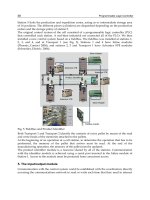
To keep use coil load as an output module, maximum opening and shutting frequency is 1 second on and 1 second off.
The following diagram shows maximum life relay for relay output.
Frequency ( 100,000)
100
50
30
20
10
100
10 5
3 2 1
0.5
Opening/shutting of electric current
AC 250V
r/load
DC 30V r/load
AC 125V r/load
Chapter 6 Input and Output Modules
Chapter 6 Input and Output ModulesChapter 6 Input and Output Modules
Chapter 6 Input and Output Modules
6
-
2
6.2 Digital Input Specification
6.2.1 Base unit
1) Specification
Base unit
K7M-DR10S
K7M-DR20S
K7M-DR30S K7M-DR40S K7M-DR60S
K7M-DR10S/DC K7M-DR20S/DC K7M-DR30S/DC K7M-DR40S/DC K7M-DR60S/DC
Model
Specification
K7M-DT10S
K7M-DT20S
K7M-DT30S K7M-DT40S K7M-DT60S
Number of input points 6 points 12 points 18 points 24 points 36 points
Insulation method Photo coupler
Rated input voltage DC12 / 24V
Rated input current 4.5 / 9 mA (P000 ~ P002 : 8 / 16mA)
Operating voltage range DC10.2 ~ 28.8V (ripple: less than 5%)
Max. simultaneous input points 100% simultaneously On
On voltage / On current DC9.5V or higher/ 3.5 mA or higher (P000 ~ P002 : 6.3mA or higher)
Off voltage / Off current DC5V or lower / 1.8 mA or lower (P000 ~ P002 : 3.3mA or lower)
Input impedance
Approx. 2.7 k
Ω
(I00~I02: approx. 1.5 k
Ω
)
Off
→
On
15ms or less *
¹
Response time
On
→
Off
15ms or less *
¹
Common terminal 6 points / COM 12 points / COM 18 points / COM 12 points / COM 18 points / COM
Operating indicator LED turns on at ON state of input
*
¹
:
It is possible to select from 1ms to 15ms by 1ms at KGLWIN.
2) Circuit diagram
Input no. P000 ~ P002
Input no. P003 ~P03F
R
R
Internal
circuit
COM
R
R
Internal
circuit
COM
C
Chapter 6 Input and Output Modules
Chapter 6 Input and Output ModulesChapter 6 Input and Output Modules
Chapter 6 Input and Output Modules
6
-
3
3) Input wiring
Base unit’s wiring method is as follows. DC input specifications offered by K80S is to be used for both electric
current sink and electric current source.
(1) 10-points base unit
(2) 20-points base unit
DC24V
DC24V
Chapter 6 Input and Output Modules
Chapter 6 Input and Output ModulesChapter 6 Input and Output Modules
Chapter 6 Input and Output Modules
6
-
4
(3) 30-point base unit
(4) 40-point base unit
DC24V
D
C
2
4V
D
C
2
4V
Chapter 6 Input and Output Modules
Chapter 6 Input and Output ModulesChapter 6 Input and Output Modules
Chapter 6 Input and Output Modules
6
-
5
(5) 60-point base unit
DC24V DC24V
Chapter 6 Input and Output Modules
Chapter 6 Input and Output ModulesChapter 6 Input and Output Modules
Chapter 6 Input and Output Modules
6
-
6
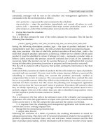
4) Example of external devices.
To connect with external device of DC output type into DC input module, wire depending on the type of the external
device as shown.
External device
Input module
Contact points
NPN open collector output type
NPN current output type
PNP current output type
Relay
IN
COM
Sensor
IN
COM +
Power for
sensor
Output
0V
+
IN
COM
-
Power for
sensor
Output
0V
+
Voltage output type
IN
COM +
Output
0V
+
Power for
sensor
7mA
Power for
sensor
IN
COM
+
Output
0V
+
+
Consta
nt
Same power for sensor
and input
7mA
7mA
7mA
Chapter 6 Input and Output Modules
Chapter 6 Input and Output ModulesChapter 6 Input and Output Modules
Chapter 6 Input and Output Modules
6
-
7
6.2.2 Expansion Module
1) Specifications
Expansion Module Model
Specification
G7E-DR10A
Number of input points 6 points
Insulation method Photo coupler
Rated input voltage DC12 / 24V
Rated input current 4.5 / 9 mA
Operating voltage range DC10.2 ~ 28.8V (ripple: less than 5%)
Max. Simultaneous input points 100% simultaneously On
On voltage / On current DC9.5V or higher/ 3.5 mA or higher
Off voltage / Off current DC5V or lower / 1.8 mA or lower
Input impedance
Approx. 2.7 k
Ω
Off
→
On
15ms or less *
¹
Response time
On
→
Off
15ms or less *
¹
Common terminal 6 points / com
Operating indicator LED turns on at ON state of input
*
¹
: It’s possible to select from 1ms to 15ms by 1ms at KGLWIN.
2) Circuit diagram
It’s the same with the one for the base unit.
3) Input wiring
DC24V
Chapter 6 Input and Output Modules
Chapter 6 Input and Output ModulesChapter 6 Input and Output Modules
Chapter 6 Input and Output Modules
6
-
8
6.3 Digital Output Specification
6.3.1 Base unit (Relay Output)
1) Specification
Base Unit
K7M-DR10S K7M-DR20S K7M-DR30S K7M-DR40S K7M-DR60S
Model
Specifications
K7M-DR10S/DC K7M-DR20S/DC K7M-DR30S/DC K7M-DR40S/DC K7M-DR60S/DC
Output point 4 points 8 points 12 points 16 points 24 points
Insulation method Relay insulation
Rated load voltage/current
DC24V / 2A (r/load), AC220V / 2A (COS
Ψ
= 1) / 1 point 5A / 1COM
Min. load Voltage/current DC5V / 1mA
Max. load voltage/current AC250V, DC110V
Current leakage when off 0.1mA (AC220V, 60Hz)
Max. On/off frequency 1,200/hr
Surge Absorber None
Mechanical More than 20,000,000
Rated on/off voltage/current load 100,000 or more
AC200V / 1.5A, AC240V / 1A (COS
Ψ
= 0.7) 100,000 or more
AC200V / 1A, AC240V / 0.5A (COS
Ψ
= 0.35) 100,000 or more
Life
Electrical
DC24V / 1A, DC100V / 0.1A (L / R = 7ms) 100,000 or more
Off
→
On
10 ms or less
Response
time
On
→
Off
12 ms or less
Common method 1 point/ 1COM, 2 points/ 1COM, 4 points/1COM
Operation indication LED is on at on status of output
2) Circuit
L
Internal
circuit
COM
L
Relay
Chapter 6 Input and Output Modules
Chapter 6 Input and Output ModulesChapter 6 Input and Output Modules
Chapter 6 Input and Output Modules
6
-
9
3) Output wiring
(1) 10-points base unit
(2) 20-points base unit
DC5V DC24V AC110/220V
L
L
L
L
L
L
L
L
AC100-240V
FG COM0
P40 P41
COM1 COM2
P42 P43
COM3 •
Chapter 6 Input and Output Modules
Chapter 6 Input and Output ModulesChapter 6 Input and Output Modules
Chapter 6 Input and Output Modules
6
-
10
(2) 30-point base unit
(3) 40-point base unit
L
DC5V DC24V AC110/220V
L
L
L
L
L
L
L
L
L
L
L
L
DC5V DC24V AC110/220V
DC24V
L
L
L
L
L
L
L
L
L
L
L
L
L
L
L
L
Chapter 6 Input and Output Modules
Chapter 6 Input and Output ModulesChapter 6 Input and Output Modules
Chapter 6 Input and Output Modules
6
-
11
(4) 60-point base unit
DC5V DC24V AC110/220V DC24V
L
LL
L
DC24V
L
LL
L
L
LL
L
L
LL
L
L
LL
L
L
LL
L
L
LL
L
L
LL
L
L
LL
L
L
LL
L
L
LL
L
L
LL
L
L
LL
L
L
LL
L
L
LL
L
L
LL
L
L
LL
L
L
LL
L
L
LL
L
L
LL
L
L
LL
L
L
LL
L
L
LL
L
L
LL
L
Chapter 6 Input and Output Modules
Chapter 6 Input and Output ModulesChapter 6 Input and Output Modules
Chapter 6 Input and Output Modules
6
-
12
6.3.2 Base unit (Transistor Output)
1) Specification
Base Unit
Model
Specifications
K7M-DT10S K7M-DT20S K7M-DT30S K7M-DT40S K7M-DT60S
Output point 4 points 8 points 12 points 16 points 24 points
Insulation method Photo Coupler insulation
Rated load voltage/current DC12 / 24V
Operating load voltage DC10.2 ~ 26.4V
Max. load current 0.5A / 1point, 3A / 1COM
Current leakage when off 0.1mA or less
Voltage drop when turn on 1.5V or less (Max. load)
Max. Inrush Current 4A, 10mA
Surge Absorber Clamp DIode
Off
→
On
2 ms or less
Response
time
On
→
Off
2 ms or less
Common method 4 point/ 1COM 8 point/ 1COM
8 point/ 1COM
4 point/ 1COM
8 point/ 1COM
( x2)
8 point/ 1COM
( x3)
Operation indication LED is on at on status of output
2) Circuit
R1
R2
D2
C2 D1
P/C
TR2
TR1
+24VD
COM
Load
Vcc
C1
Chapter 6 Input and Output Modules
Chapter 6 Input and Output ModulesChapter 6 Input and Output Modules
Chapter 6 Input and Output Modules
6
-
13
(3) Wiring Diagram
1) 10-point base unit
2) 20-point base unit
3) 30-point base unit
L L
L L
L L
L L
L L
L L
L L
L L
L L
L L
L L
L L
Chapter 6 Input and Output Modules
Chapter 6 Input and Output ModulesChapter 6 Input and Output Modules
Chapter 6 Input and Output Modules
6
-
14
4) 40-point base unit
5) 60-point base unit
L L
L L
L L
L L
L L
L L
L L
L L
L L
L L
L L
L L
L L
L L
L L
L L
L L
L L
L L
L L
Chapter 6 Input and Output Modules
Chapter 6 Input and Output ModulesChapter 6 Input and Output Modules
Chapter 6 Input and Output Modules
6
-
15
6.3.3 Expansion Module
1) Specifications
Expansion Module
Model
Specifications
G7E-DR10A
Output point 4 points
Insulation method Relay insulation
Rated load
Voltage/current
DC24V / 2A (r/load), AC220V / 2A (COS
Ψ
= 1) / 1 point 5A / 1COM
Min. load Voltage/current DC5V / 1mA
Max. load voltage/current AC250V, DC110V
Current leakage when off 0.1mA (AC220V, 60Hz)
Max. On/off frequency 1,200/hr
Surge Absorber None
Mechanical More than 20,000,000
Rated on/off voltage/current load 100,000 or more
AC200V / 1.5A, AC240V / 1A (COS
Ψ
= 0.7) 100,000 or more
AC200V / 1A, AC240V / 0.5A (COS
Ψ
= 0.35) 100,000 or more
Life
Electrical
DC24V / 1A, DC100V / 0.1A (L / R = 7ms) 100,000 or more
Off
→
On
10 ms or less
Response time
On
→
Off
12 ms or less
Common method 1 point/ 1COM, 2 points/ 1COM
Operation indication LED is on at on status of output
2) Circuit
It’s the same with the output circuit of the base unit.
3) Output wiring
REMARK
1) Refer to 7.2 ‘Special Functions’ for the special function units
DC5V
L
L L L
DC24V
AC110/220V