User’s Manual LG Programmable Logic Controller - Chapter 7 potx
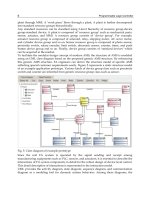
Bạn đang xem bản rút gọn của tài liệu. Xem và tải ngay bản đầy đủ của tài liệu tại đây (1.6 MB, 66 trang )
Chapter 7 Usage of Various Functions
7-1
Chapter 7 Usage of Various Functions
7.1 Built-in Functions
7.1.1 High-speed counter function
This chapter describes the specification, handling, and programming of built-in high speed counter of MK80S. The built-in
high speed counter of MK80S(hereafter called HSC) has the following features;
3 counter functions as followings
- 1-phase up / down counter : Up / down is selected by user program
- 1-phase up / down counter : Up / down is selected by external B phase input
- 2-phase up / down counter : Up / down is automatically selected by the phase difference between A-phase and B.
Multiplication (1, 2, or 4) with 2-phase counter
- 2-phase pulse input multiplied by one : Counts the pulse at the leading edge of A-phase.
- 2-phase pulse input multiplied by two : Counts the pulse at the leading / falling edge of A-phase.
- 2-phase pulse input multiplied by four : Counts the pulse at the leading / falling edge of A-phase and B
1) Performance Specifications
Items Specifications
Types A-phase, B-phase, Preset
Rated level 24VDC (15mA)
Input signal
Signal type Voltage input
Counting range 0 ~ 16,777,215 (Binary 24 bits)
Max. counting speed 1-phase 16kHz/ 2-phase 8kHz
1-phase Sequence program or B-phase input
Up / Down
selection
2-phase Auto-select by phase difference of A-phase and B
Multiplication 1, 2, or 4
Preset input Sequence program or external preset input
2) Input specification
Items Specifications
Rated input 24VDC (15mA)
On voltage 14VDC or higher
A / B phase
Off voltage 2.5VDC or lower
Rated input 24VDC (15mA)
On voltage 19VDC or higher
Off voltage 6V or lower
On delay time Less than 1.5ms
Preset input
Off delay time Less than 2ms
Chapter 7 Usage of Various Functions
7-2
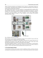
3) Names of wiring terminals
No.
Terminal No. Names Usage
①
P00
φ
A 24V
A Phase input terminal
②
P01
φ
B 24V
B Phase input terminal
③
P02
Preset 24V
Preset input terminal
④
COM0
Common input
Common terminal
4) External interface circuit
I/O Internal circuit
Terminal
No.
Signal name
Operation
Input warranted
voltage
On 14 ~ 26.4 V
P00
A-phase pulse
Input (DC24V)
Off 2.5V or lower
On 14 ~ 26.4 V
P01
B-phase pulse
Input (DC24V)
Off 2.5V or lower
Input
COM0
COM
(input common)
On 19 ~ 26.4 V
P02
Preset input
(DC24V)
Off 6V or lower
Input
COM0
COM
(input Common)
1.5 K
Ω
820
Ω
1.5 k
Ω
1.5 k
Ω
820
Ω
8
2
0
Ω
BUILT_IN CNET
ON
ROM MODE
OFF
P00
P01
P02
P03
P04
①
②
③
Counter in
p
ut
Preset input
④
24G
COM0
24V
P12
P0C
P1A
P0B P09 P05
I05
Chapter 7 Usage of Various Functions
7-3
5) Wiring instructions
A high speed pulse input is sensitive to the external noise and should be handled with special care. When wiring the built-
in high speed counter of MK80S, take the following precautions against wiring noise.
(1) Be sure to use shielded twisted pair cables. Also provide Class 3 grounding.
(2) Do not run a twisted pair cable in parallel with power cables or other I/O lines which may generate noise.
(3) Before applying a power source for pulse generator, be sure to use a noise-protected power supply.
(4) For 1-phase input, connect the count input signal only to the phase A input; for 2-phase input, connect to phases A
and B.
6) Wiring example
(1) Voltage output pulse generator
Pulse Generator
CHSC
A
B
COM
24V
24VG
(2) open collector output pulse generator
Pulse Generator
CHSC
A
B
COM
24V
24VG
Pulse Generator
Chapter 7 Usage of Various Functions
7-4
7) Instruction
When use the built-in high speed counter of K80S, the HSC instruction should be used. The instruction format of HSC is as
following;
When the value of operation mode (D4999), PV or SV is not proper, the instruction error flag (F110) turns on and the HSC
instruction is not executed.
Input terminal Operation mode
(D4999)
A phase B phase Preset
Multiplication Description
h1000
Pulse
input
– – –
U/D : Set by sequence program
PR : Set by sequence program
h1010
Pulse
input
– Preset input –
U/D : Set by sequence program
PR : Set by preset input
h1100
Pulse
input
U/D input – –
U/D : Set by U/D input
PR : Set by sequence program
1 phase
h1110
Pulse
input
U/D input Preset input –
U/D : Set by U/D input
PR : Set by preset input
h2001
A-phase
input
B-phase
input
– 1
PR : Set by sequence program
1 multiplication
h2002
A-phase
input
B-phase
input
– 2
PR : Set by sequence program
2 multiplication
h2004
A-phase
input
B-phase
input
– 4
PR : Set by sequence program
4 multiplication
h2011
A-phase
input
B-phase
input
Preset input 1
PR : Set by preset input
1 multiplication
h2012
A-phase
input
B-phase
input
Preset input 2
PR : Set by preset input
2 multiplication
2 phase
h2014
A-phase
input
B-phase
input
Preset input 4
PR : Set by preset input
4 multiplication
Remark
The U/D and PR input of sequence program must be programmed with dummy input even they are set as external
input. When the PR and/or U/D is set as external input, the input conditions of sequence program is ignored.
HSC
EN
U/D PV ( )
PR SV ( )
Chapter 7 Usage of Various Functions
7-5
1) EN input (Counter enable)
When the EN input turns on, the counter starts counting pulse. When the EN is off, the counting is stopped and the current
value of high speed counter is cleared as 0.
2) U/D input (Up/down)
When the U/D input is off, the high speed counter operates as up counter. When the U/D is off, it operates as down-counter.
3) PR input (Preset)
When the PR input is on, the current value of high speed counted is replaced with the preset value (PV).
4) Output relay (F0170)
The F070 bit will be turn on when the current value of high speed counter (F18 : lower word, F19 : upper word) is equal of
greater than the set value (SV).
5) Carry flag (F0171)
The carry flag turns on when the current value of high speed counter is underflow ( 0 Æ 16,777,215 ) during down counting
or overflow ( 16,777,215 Æ 0 ) during up counting.
6) Current value
The current value of high speed counter is stored at two words, F18 and F19. The lower word is stored at F18, and upper
word is stored at F19.
Chapter 7 Usage of Various Functions
7-6
8) example program
(1) 1-phase operation mode (U/D by program : D4999 = h1010)
U/D : set by sequence program (M001)
PR : set by external PR input
Ladder diagram
Time chart
HSC
EN
U/D PV D0000
PR SV D0010
MOV 100 D0000
MOV 01000 D0010
A
-
p
hase
p
ulse in
p
ut
U/D in
p
ut
(
M001
)
Current value of HSC 0 2 3 4 3 2 1 1
F12
M000
MOV h1010 D4999
0
1
M001
M002
Chapter 7 Usage of Various Functions
7-7
(2) 1-phase operation mode (U/D by B phase : D4999 = h1100)
U/D : set by external input (B-phase input)
PR : set by sequence program (M002)
Ladder diagram
Time chart
HSC
EN
U/D PV 00100
PR SV 01000
MOV h1100 D4999
M000
A
-
p
hase
p
ulse in
p
ut
B-
p
hase in
p
ut
(
U/D
)
PR in
p
ut
(
M002
)
Current value of HSC 10 08 09 10 11 100 101 09
F012
M001
M002
Chapter 7 Usage of Various Functions
7-8
(3) 2-phase operation mode (1 Multiplication Operation : D4999 = h2011)
U/D : set automatically by the phase difference between A and B phase
PR : set by external PR input
Multiplication : 1
Ladder diagram
Time chart
HSC
EN
U/D PV 00100
PR SV 01000
MOV h2011 D4999
M000
A
-
p
hase
p
ulse in
p
ut
B-
p
hase in
p
ut
(
U/D
)
Current value of HSC 10 12 13 14 13 12 11 11
F012
M001
M002
Chapter 7 Usage of Various Functions
7-9
4) 2-phase operation mode (2 Multiplication Operation : D4999 = 2012)
U/D : set automatically by the phase difference between A and B phase
PR : set by external PR input
Multiplication : 2 times
Ladder diagram
Time chart
HSC
EN
U/D PV 00100
PR SV 01000
MOV h2012 D4999
M000
A
-
p
hase
p
ulse in
p
ut
B-
p
hase in
p
ut
(
U/D
)
Current value of HSC 10 12 13 14 15 16 17 18 17 16 15 14 13 12 11
M001
M002
F012
Chapter 7 Usage of Various Functions
7-10
(5) 2-phase operation mode (4 Multiplication Operation : D4999 = h2014)
U/D : set automatically by the phase difference between A and B phase
PR : set by external PR input
Multiplication : 4 times
Ladder diagram
Time chart
HSC
EN
U/D PV 00100
PR SV 01000
MOV h2014 D4999
M000
A
-
p
hase
p
ulse in
p
ut
B-
p
hase in
p
ut
(
U/D
)
Current value of HSC 10 14 16 18 20 22 24 25 23 21 19 17 15 12
15 19 23 24 20 16 11 17 21 25 22 18 14 13
F012
M001
M002
Chapter 7 Usage of Various Functions
7-11
7.1.2. Pulse Output Function
In the transistor output type of MK80S, the pulse output function - maximum 2Kpps - is internalized. By using this function with
stepping motor or servo motor driver, MK80S is applicable to a simple positioning system.
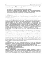
1) Usage of the Pulse Output
Transistor output type of MK80S outputs the signals of pulse and direction in an output contact point through the
instruction (PULSOUT). The outputted pulse is connected to motor driver it is controlled position in the following figure.
Choose a mode from the pulse out function by parameter setting and operate following 3 modes
(1) Trapezoidal operation
The pulse output function operates in order of acceleration – uniform velocity – deceleration.
(2) Uniform velocity operation
Operates with the uniform velocity without increasing/decreasing operation
(3) Infinite operation
Operate infinitely without an increasing/decreasing operation until meet the emergency stop command.
time
velocit
y
increasin
g
decreasin
g
time
velocit
y
time
velocit
y
driver
K7M-DT30S
motor
pulse
direction
Chapter 7 Usage of Various Functions
7-12
2) Functional Specification
Item
Specification
No. of output 1 point
Output type
Pulse
Output velocity Max 2Kpps, Min 50pps
Output pulse 0 ~ 2147483647
Execution type of the increasing/decreasing velocity Designation of acceleration
Type of the direction designation Right/opposite direction pulse output
Load power supply
DC 12V/24V
Usable range of the load power supply
DC10.2 ~ 26.4V
Maximum load current
150mA
Initiative electric current Less than 0.4A, 10ms
Maximum power dropdown under On Less than DC 0.5V
Electric current leakage under Off Less than 0.1mA
On delayed time Less than 1ms
Off delayed time Less than 1ms
1) Several points can be used for the pulse output point if they are not output at the same time. Thus it is
possible that right direction pulse is output as P040, opposite direction pulse is output as P041.
Remark
Chapter 7 Usage of Various Functions
7-13
3) Names of parts
No.
Terminal No.
Names
Usage
①
P40
Pulse output
Pulse output terminal of right direction
②
COM0
Common
Pulse output common terminal
③
P41
Direction output
Direction output terminal
④
COM0
Common
Direction output common terminal
If the motor drive is not input direction, but is input right/opposite direction pulse (the opposite direction pulse
can be output through using 2 instruction (PULSOUT) to P41 contact point
①
②
③
Out
p
ut
p
ulse
④
AC100-240V
FG COM0
P40
COM1
P41
COM2
P42
Out
p
ut direction
Motor driver
Stepping motor
Remark
Chapter 7 Usage of Various Functions
7-14
4) Internal circuit and external wiring
Be careful about the counter plan of the noise during the wiring in the pulse output.
1) Use twisted pair shields wire for wiring and execute 3rd contact point.
2) Be sure to separate from the power supply line and I/O lines on which noise usually occurs.
3) Length of wire should be as short as possible.
4) Be sure to use the stable power supply for the pulse output and separate it from I/O power supply.
P41 - direction output
+12/24V – power supply input(12/24V
DC)
R
COM0 – output common
R
P40
–
pulse output
Internal circuit
Internal circuit
R
R
internal circuit
R
R
power
su
pp
l
y
-
+
Motor
driver
(
24V
)
K7M-DT30S
(
Transistor out
p
ut
external wiring
Remark
Chapter 7 Usage of Various Functions
7-15
5) The setting of pulse out parameter
The setting of pulse out parameter set KGLWIN. Setting windows is as below.
It is possible to set 40 operational pattern.
When click the pattern no. parameter setting window is displayed as bellow
6) parameter explanation
(1) operational pattern No.
operation pattern No. is each pulse out pattern No. Max. 40 patterns can be set
(2) Output pulse count
It sets output pulse number.(The setting range : 0 ~ 42944967295)
(3) Max speed
It sets operational speed at normal section (The setting range : 50 ~ 2000pps,
50multiflier only)
(4) Acceleration/ Deceleration mode
Acceleration/ Deceleration mode is designation of increasing/decreasing velocity operation
Disable : uniform velocity operation enable : increasing/decreasing velocity operation
(5) Acceleration/deceleration slop
Acceleration slop is available in case that acceleration/deceleration mode is enable
This is slop that pulse frequency reach to maximum pulse frequency from ‘0’ pulse. (only integer)
(6) Bit device set
a) Direction contact signal
setting of contact for direction signal output
Chapter 7 Usage of Various Functions
7-16
b) continuous operation
setting of contact for infinitive operation
c) emergency stop
setting of contact for emergency stop
(7) The number of acceleration pulse
Automatically calculate at KGL-WIN if the maximum pulse and slop are set by user
Calculation method is as below
The number of acceleration pulse = [(maximum pulse – 50) / 50 +( maximum pulse – 100) / 50 + ∙∙∙∙∙∙∙∙∙∙∙∙ +
(100 / 50) + (50 / 50) ] x acceleration slop x 2
ex) maximum pulse : 1000pps , acceleration slop : 1
The number of acceleration pulse = [(1000 – 50) / 50 + (900 – 50) / 50 + ∙∙∙∙∙∙∙∙∙∙∙∙ +(100 /50 ) + (50 /50) ] x 1 x 2
= 380 (deceleration pulse is also 380)
(8) acceleration time
Automatically calculate at KGL-WIN if the maximum pulse and slop are set by user.
Calculation method is as below
acceleration time = [[(maximum pulse – 50) / 50] x acceleration slop x 10
ex) maximum pulse : 1000pps , acceleration slop : 1
acceleration time = [[(1000 – 50) / 50] x 1 x 10 = 380ms (deceleration time is also 380ms)
Acceleration slop and deceleration slop of MK80S pulse output are set up as the same. Set up proper value by the
sort of motor because if a/d slop increases, the arrival time to the designated max. Cycle also increases.
Remark
Chapter 7 Usage of Various Functions
7-17
7) pulse out operation explanation
Condition 1)
Set up as acceleration slop = 1, max. frequency = 1000, no of pulse out = 5000.
① If as acceleration slop = 1, 1 pulse is output on the 1st step (velocity: 50pps).
Pulse velocity is 50pps, so time consuming is 20ms.
② 2 pulses are output on the 2nd step (velocity: 100pps) and time consumes 20ms
③ By calculation in the same way, the time to reach to 1000pps is
20ms x (20-1) = 380ms, and the no. of output pulses are 1+2+3 +18+19 = 190 units.
④
Decreasing velocity inclination is 1, thus 190 units of pulses are needed.
⑤
The no. of pulses in the uniform velocity region are 5000-190-190=4,620 units.
⑥
Whole spent time is 50,380ms
Time
velocity
Acceleration time:380ms
Accelerating pulses:190
Deceleration
20ms
50pps
Acceleration step : 19
Uniform velocity
Time :4,620ms
Pulses :4,620
Deceleration time :380ms
Decelerating pulses:190
1st step
2
nd
step
example: when acceleration is 1.
Chapter 7 Usage of Various Functions
7-18
Condition 2
Set up as acceleration slop = 2, max. frequency = 1000, no of pulse out = 5000.
① If I/D velocity inclination is 2, 2 pulses are output on the 1st step(velocity: 50pps).
Pulse velocity is 50pps. So time consuming is 40ms.
② 4 pulses are output on the 2nd step(velocity: 100pps) and time consumes 20ms
③ By calculation in the same way, the time to reach to 1000pps is 40ms * (20-1) = 760ms,
and the no. of output pulses are 2+4+6 +36+38 = 380 units.
④
Decreasing velocity inclination is 2, thus 380 units of pulses are needed.
⑤
The no. of pulses in the uniform velocity region are 5000-380-380=4,240 units.
⑥
Whole spent time is 57,600ms
If the acceleration slop goes bigger, the increasing time and pulse go bigger by direct proportion to inclination.
Then be careful of an occurring of the instruction error when the no. of a/d pulse becomes bigger than the no.
of whole pulse.
A
cceleration
Time:760ms
Pulses:380
40ms
50pps
Uniform velocity
Time:4,240ms
Pulses:4,240
Deceleration
Time:760ms
Pulses:380
Example) Acceleration is 2.
Time
velocity
Deceleration Acceleration step : 19
1st step
2
nd
step
Remark
Chapter 7 Usage of Various Functions
7-19
8) instruction
Available Device Flag
Instructions
M P K L F T C S D #D
Inte-
ger
Steps
Error
(F110)
Zero
(F111)
Carry
(F112)
O O
O O O O O O O O
DUTY
O
7
O
(1) Functions
- ‘n’ designates pattern no. which is registered at parameter.
- S1 designates device name which will be stored output pulse count no. and error code .(3 word)
- S2 designates output device (output P area ) .
(2) example of program
when the M0020 is ‘On’ ,it outputs the pulse at 5 pattern to P0040.
It stores the output pulse count no. at D0000 and D0001.
It stores error information at D0002.
All output area is designated for pulse output contact , but it can’t designate over 2 contact at the same time.
Pattern no.
PLSOUT S
1
S
2
D
Output pulse count no.
Output pulse contact
S
3
S
1
S
2
S
2
n
n
PLSOUT 5 D0000 P0040
M0020
Chapter 7 Usage of Various Functions
7-20
(3) instruction Error List
Error status
Contents
Treatment
00
Normal
-
01
Other PLSOUT instruction pulsating.
Change the other PLCOUT program.
02
Velocity designation error (more than 2000, not a
multiple of 50, designated 0)
Velocity designation adjustment
03
The no. of a/c velocity pulse is bigger than no. of all
pulse is to output.
Acceleration adjustment
04
No output contact point where is designated to the pulse
output
Output contact point designation
05
No output contact point where is designated to the
direction output
Output contact point designation
Chapter 7 Usage of Various Functions
7-21
9) Output Direction
Input type of servo motor driver or stepping motor driver is subdivided into 2. Output direction of control can be
selected in the pulse output parameter.
(1) Selecting method of output direction
a) When driver gets input forward direction pulse and reverse direction pulse contact point, and the
forward/reverse direction signals one levels.
Parameter setting
Direction contact designates P51.
(Example of a program)
When the M000 is on, direction contact ‘P51’ is set, and pulse outputs at pattern ‘0’(forward direction output)
When the M001 is on, direction contact ‘P51’ is reset, and pulse outputs at pattern ‘0’(reverse direction output)
Be careful If direction bit use another purpose , pulse output operates abnormally.
Forward direction out
p
ut
Reverse direction output
Output pulse
(P50)
Output dir.
(P51)
time
velocity
acceleration slop 1
decelerationslop:
1
Set velocity = 1Kpps
Initial position
Set position = 5000
(velocity Profile)
Chapter 7 Usage of Various Functions
7-22
b) Driver gets input forward direction pulse and reverse direction pulse through different contact points.
Parameter setting
Program
F210 turns on while the pulse output is operating.
Forward operation Reverse operation
Reverse
direction
(P51)
Forward
direction
(P50)
Time
Forward
direction
Target velocity = 1Kpps
Forward dir.
Start
p
oint
Reverse
direction
Target
position=10000
Reverse dir. star
t
p
oint
Target
p
osition
=
5000
Target velocity = 1Kpps
Velocit
y
Profile
Chapter 7 Usage of Various Functions
7-23
7.1.3. Pulse Catch Function
In the base unit, 8 points of pulse catch input contact points(P000 ~ P007) are internalized. Through using this contact
point short pulse signal, short as 0.2ms, can be taken which can not be executed by general digital input.
1) Usage
When narrow width of pulse signal is input, a trouble occurs which can not be detected by general digital input, so the
operation does not perform as user's intention. But in this case through pulse catch function even narrow interval of pulse
signal as 0.2ms min can be detected.
2) Operating Explanation
input signal
input image data
step executing contents
scan1 CPU senses input when pulse signal, min. 0.2ms, is input, then saves the status.
scan2 used to turn on the region of input image
scan3 used to turn off the region of input image
3) using method
(1) click twice the basic parameter on the project window of KGLMIN
(2) Select no. to use for pulse catch input of the basic parameter window.
For details of KGLWIN refers to the manual.
scan 1 scan 2 scan 3
Chapter 7 Usage of Various Functions
7-24
1) 8 points can be used to designate the pulse catch input. The input address is from P000 to P007.
2) General digital input operates if it is not designated as pulse catch input.
Remark
Chapter 7 Usage of Various Functions
7-25
7.1.4. Input Filter Function
External input of MK80S selects input on/off delay time from the range of 0-15ms of KGLWIN. Credibility secured system
may be established by adjustment of input correction no. through using environment.
1) Usage
Input signal status affects to the credibility of system in where noise occurs frequently or pulse width of input signal affects
as a crucial factor. In this case the user sets up the proper input on/off delay time, then the trouble by miss operation of
input signal may be prevented because the signal which is shorter than set up value is not adopted.
2) Operating Explanation
narrower width pulse than input correction no. is not considered as input signal
3) Using method
(1) Click twice the basic parameter on the project window of KGLWIN.
(2) The value of filter can be set up as unit of 1ms to the input on/off delay time of the basic parameter window.(Input
on/off delay time is set up as default value of 8ms)
(3) Set up input on/off delay time is conformed to all input is used.
input signal
input image data
in
p
ut si
g
nal
in
p
ut ima
g
e data
time
in
p
ut
on/off dela
y
time
.
(
filter time
)
Itcanbeselectedto0
~
15ms.