User’s Manual LG Programmable Logic Controller - Chapter 8 doc
Bạn đang xem bản rút gọn của tài liệu. Xem và tải ngay bản đầy đủ của tài liệu tại đây (1.14 MB, 77 trang )
Chapter8 Communication Function
8-1
Chapter 8 Communication Function
8.1 Dedicated Protocol Communication
8.1.1 Introduction
MK80S’s built-in Cnet communication uses only MK80S base unit for a dedicated communication. That is, it
doesn’t need a separate Cnet I/F module to facilitate the user-intended communication system by utilizing
reading or writing of any area in CPU, and monitoring function.
MK80S base unit serves as follows:
• Individual/continuous reading of device
• Individual/continuous writing of device
• Reading CPU status
• Monitor devices registration
• Executing monitoring
• 1:1 connection(link between MASTER-K’s) system configuration (MK80S base unit:
RS-232C)
Remark
MK80S built-in communication function supports Cnet communication without any separate Cnet module. It
must be used under the following instructions.
1) MK80S base unit supports 1:1 communication only. for 1:N system having master-slave Format, use
MK80S base unit with G7L-CUEC module connected. G7L-CUEC module supports RS-422/485 protocol.
(10-point main unit includes RS-485 communication terminal, so 1:N system can be configured without
G7L-CUEC module)
2) RS-232C communication cable for MK80S base unit is different from RS-232C cable for KGL_WIN in pin
arrangement and from the cable for Cnet module, too. The cable can’t be used without any treatment. For
the detailed wiring method, refer to 8.1.2.
3) It’s possible to set baud rate type and M area size in KGL_WIN. For the detailed information, refer to the
appendix or KGLWIN manual.
Chapter8 Communication Function
8-2
8.1.2 System configuration method
According to the method of connection, the system using MK80S built-in communication can be
composed.
1) Connecting system configuration (link between MASTER-K’s)
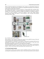
(1) 1:1 connection with general PC
a) Communication program made by C or BASE computer language on the user’s computer, or
utility program like MMI software can be used.
b) Wiring method
PC MK80S base unit
Pin No.
Pin assignment And direction
Pin No. Signal
1 1 5V
2 2 RXD1
3 3 TXD1
4 4 RXD2
5 5 SG
6 6 5V
7 7 TXD2
8 8 SG
9
9 SG
TXD1,RXD1 are for loader communication and TXD2,RXD2 are for Cnet
1
2
3
4
5
6
7
8
9
Female Type
RS-232C interface
K80S base unit
Chapter8 Communication Function
8-3
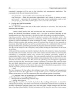
(2) 1:1 connection with a monitoring device like PMU
PMU MK80S base unit
Pin No.
Pin assignment and direction
Pin no. Signal
1 1 5V
2 2 RXD1
3 3 TXD1
4 4 RXD2
5 5 SG
6 6 5V
7 7 TXD2
8 8 SG
9
9 SG
1
2
3
4
5
6
7
8
9
PMU(LGIS) K80S base unit
RS-232C interface
Female Type
Chapter8 Communication Function
8-4
.
(3) 1:1 connection with other MK80S
For the detailed information, refer to 8.1.7 “1:1 Dedicated Protocol Communication.”
MK80S base
unit
MK80S base unit
Pin no.
Pin assignment and direction
Pin no. Signal
1 1 5V
2 2 RXD1
3 3 TXD1
4 4 RXD2
5 5 SG
6 6 5V
7 7 TXD2
8 8 SG
9
9 SG
1
2
3
4
5
6
7
8
9
K80S base unit
RS-232C interface
K80S base unit
Male Type
Chapter8 Communication Function
8-5
8.1.3 Frame Structure
1) Base Format
(1) Request frame(external communication device → MK80S base unit)
(Max. 256 Bytes)
Header
(ENQ)
Station
number
Command
Command
type
Structurized data area
Tail
(EOT)
Frame check
(BCC)
(2) ACK Response frame (MK80S base unit → external communication device, when receiving data
normally)
(max. 256 Bytes)
Header
(ACK)
Station
number
Command
Command
type
Structurized
data area or null code
Tail
(ETX)
Frame check
(BCC)
(3) NAK Response frame (MK80S base unit → external communication device, when receiving data
abnormally)
(max. 256 Bytes)
Header
(NAK)
Station Command
Command
type
Error code (ASCII 4 Byte)
Tail
(ETX)
Frame check
(BCC)
Remark
1) Used control codes are as follows. Be familiar with the following control codes. Because they are importantly
used for communication.
[Control codes]
Codes Hex value Name Contents
ENQ H05 Enquire Request frame initial code
ACK H06 Acknowledge ACK response frame initial code
NAK H15 Not Acknowledge NAK response frame initial code
EOT H04 End of Text Request frame ending ASCII code
ETX H03 End Text Response frame ending ASCII code
Chapter8 Communication Function
8-6
Remark
1) The numerical data of all frames are ASCII codes equal to hexadecimal value, if there’s no clear
statement. The terms in hexadecimal are as follows.
•
Station No.
•
When the main command is R(r) or W (w) and the command type is numerical (means a data type)
•
All of the terms indicating size of all data in the Formatted data area.
•
Monitoring registration and command registration number of execution commands.
•
All contents of data
Remark
1) If it is hexadecimal, H is attached in front of the number of frames like H01, H12345, H34, H12, and H89AB.
2) Sequence of command frame
(1) Sequence of command request frame
ENQ Station No. Command Fomatted data EOT BCC (PLC ACK response)
ACK Station No. Command Data or null ETX BCC
NAK Station No. Command Error code ETX BCC
(PLC NAK response)
Chapter8 Communication Function
8-7
8.1.4 List of commands
Command list for communication.
Command
Main command Command type
Division
Item
Code ASCII code Code ASCII code
Treatment
Individual
reading
r(R)
H72
(H52)
SS 5353
Reads device of Bit, Word and type.
Reading
device
Continuos
reading
r(R)
H72
(H52)
SB 5342
Reads device Word in block unit.
(Continuous reading Bit is unavailable)
Individual
reading
w (W)
H77
(H57)
SS 5353
Writes data to device of Bit and Word type.
Writing
device
Continuos
reading
w(W)
H77
(H57)
SB 5342
Writes data to Word type in block unit.
(Continuous reading Bit is unavailable)
CPU
Status reading
r(R)
H73
(H53)
ST 5354
Reads flag list like PLC operation status and error
information. (For detailed flag contents, refer to
MK80S manual).
Command
Main command Register No.
Division
Item
Code ASCII code
Register
no.
ASCII code
Treatment
Monitoring variable
register
x(X)
H78
H58
H00~H09 3030 ~ 3039 Register device to monitor.
Execution of
monitoring
y(Y)
H79
(H59)
H00~H09 3030 ~ 3039 Execute registered device to monitor.
Remark
1) MK80S base unit identifies capitals or small letters for main commands, but not for the others.
2) If it’s a main command in capitals, it calculates BCC value. But if it’s not, it doesn’t. Therefore, when BCC for
frame check is used, main commands must be in small letters.
Chapter8 Communication Function
8-8
8.1.5 Data type
It’s possible to read and write device in built-in communication. When device is used, be aware of data type.
1) Data type of variable
• Available types of device : P,M,L,K,C,T,D,S,F
• When variable is used, attach ‘%’(25H) in front of the marking characters.
Data type Marking characters Examples
Bit X(58H) %PX000, %MX000, %LX000, %KX000, %CX000, %TX000, %FX000
Word W(57H)
%PW000, %MW000, %LW000, %KW000, %CW000, %TW000,
%FW000, %DW000, %SW000
Device Name Explanation Read/Write Bit/Word Assignment
P Input/Output relay Available Both
M Auxiliary relay Available Both
L Link relay Available Both
K Keep relay Available Both
C Counter Available Both
T Timer Available Both
D Data Register Available Word Only
S Step relay Available Word Only
F Special relay Read Only Both
Remark
1) Timer/Counter used in word command means current values.
2) Data register and Step relay can uses only word commands.
3) When Link module is used, Link relay must not written.(it cause communication error)
Chapter8 Communication Function
8-9
8.1.6 Execution of commands
1) Individual reading of device(RSS)
(1) Introduction
This is a function that reads PLC device specified in accord with memory data type. Separate device
memory can be read up to 16 at a time.
(2) PC request format
Format name Header
Station
No.
Command
Command
type
Number
of blocks
Device
length
Device name Tail
Frame
check
Ex. of frame ENQ H20 R(r) SS H01 H06 %MW100
EOT BCC
ASCII value H05 H3230 H52(72) H5353 H3031 H3036 H254D57313030 H04
Item Explanation
BCC
When command is lowercase(r), only one lower byte of the value resulted by adding 1 Byte
each to ASCII values from ENQ to EOT is converted into ASCII and added to BCC. For
example, the BCC of the above frame is gotten as below:
H05+H32+H30+H72+H53+H53+H30+H31+H30+H36+H25+H4D+H57+H31+H30+H30+H04
=H03A4 Therefore BCC value is A4.
Number of
Blocks
This specifies how much of the blocks composed of "[device length][device name]" are in this
request format. This can be set up to 16. Therefore, the value of [Number of blocks] must be
set between H01(ASCII value:3031)-H10(ASCII value:3030).
Device
length(Name
length of device)
This indicates the number of name's characters that means device, which is allowable up to 16
characters. This value is one of ASCII converted from hex type, and the range is from
H01(ASCII value:3031) to H10(ASCII value:3130). For example, if the device name is %MW0,
it has 4 characters to be H04 as its length. If %MW000 characters to be H06.
Device name
Address to be actually read is entered. This must be ASCII value within 16 characters, and in
this name, digits, upper/lower case, '%' only is allowable to be entered.
1 block(setting can be repeated up to max. 16 blocks)
Chapter8 Communication Function
8-10
Remark
1) Numerical data of frame(Ex.) is hex value, and "H" is unnecessary during preparing real frame.
2) Device data type of each must be same. If data type of the first block is WORD, and the second block is
BIT, error occurs.
(3) Response format (ACK response)
Format name Header
Station
No.
Command
Command
type
Number of
blocks
Number
of data
data Tail
Frame
check
Ex. of frame ACK H20 R(r) SS H01 H02 HA9F3
ETX BCC
ASCII value H06 H3230 H52(72) H5353 H3031 H3032 H41394633 H04
1 block(max. 16 blocks possible)
Item Explanation
BCC
When command is lowercase(r), only one lower byte of the value resulted by adding 1 Byte
each to ASCII values from ACK to ETX is converted into ASCII and added to BCC, and
sent.
Number of data
Number of data means byte number of hex type, and is converted into ASCII. This number
is determined according to data type(X,W) included in device name of computer request
Format.
Number of data in accordance with its data type is as follows:
Data • In data area, there are the values of hex data converted to ASCII code saved.
Ex.1
The fact that number of data is H04(ASCII code value:H3034) means that there is hex data of 4 bytes in data .
Hex data of 4 bytes is converted into ASCII code in data.
Data type Available variable Number of data
Bitl(X) %(P,M,L,K,T,C,F)X 1
Word(W) %(P,M,L,K,T,C,D,S,F)W 2
Chapter8 Communication Function
8-11
Ex.2
If number of data is H04 and the data is H12345678, ASCII code converted value of this is "31 32 33 34 35 36 37
38," and this contents is entered in data area. Name directly, highest value is entered first, lowest value last.
Remark
1) If data type is Bit, data read is indicated by bytes of hex. Namely, if Bit value is 0, it indicated by H00, and if
1, by H01.
(4)
Response format (NAK response)
Format name Header Station No. Command Command type
Error code
(Hex 2 Byte)
Tail Frame check
Ex. of frame NAK H20 R(r) SS H1132 ETX BCC
ASCII value H15 H3230 H52(72) H5353 H31313332 H03
Item Explanation
BCC
When command is lowercase(r), only one lower byte of the value resulted by adding 1
Byte each to ASCII values from NAK to ETX is converted into ASCII and added to BCC.
Error code
Hex and 2 bytes(ASCII code, 4 bytes) indicate error type. For the details, see 8.1.8 Error
codes.
Chapter8 Communication Function
8-12
(5) Example
This example supposes when 1 WORD from M20 and 1 WORD from P001 address of station No.1 are
read and BCC value is checked. Also it is supposed that H1234 is entered in M20, and data of H5678 is
entered in P001.
① Computer request format (PC → MK80S Base Unit)
Format name Header Station No. Command
Command
type
Number of
blocks
Variable
length
Format
name
Devicelength Format name Tail
Frame
check
Ex. of frame ENQ H01 r SS H02 H05 %MW20 H06 %PW001 EOT BCC
ASCII value H05 H3031 H72 H5353 H3032 H3035
H254D57
3230
H3036
H25505730
3031
H04
② For ACK response after execution of command(PC ← MK80S Base Unit)
Format name Header Station No. Command
Command
type
Number of
blocks
Number of
data
Data
Number of
data
Data Tail
Frame
check
Ex. of frame ACK H01 r SS H02 H02 H1234 H02 H5678 ETX BCC
ASCII value H06 H3031 H72 H5353 H3032 H3032 H31323334 H3032 H35363738 H03
③ For NAK response after execution of command(PC ← MK80S Base Unit)
Format name Header Station No. Command Command type Error code Tail Frame check
Ex. of frame NAK H01 r SS
Error code (2)
ETX BCC
ASCII value H15 H3031 H72 H5353
Error code (4)
H03
※ Frame check BCC is automatically calculated internally.
K80S base unit
Chapter8 Communication Function
8-13
2) Continuous reading(RSB) of device
(1) Introduction
This is a function that reads the PLC device memory directly specified in accord with memory data type.
With this, data is read from specified address as much as specified continuously.
(2) PC request format
Format name Header
Station
No.
Command
Command
type
Device
length
Device
Number of data
(Max. 128 Bytes)
Tail
Frame
check
Ex. of frame ENQ
H10
R(r)
SB H06 %MW100 H05
EOT BCC
ASCII value H05
H3130
H52(72)
H5342 H3036 H254D57313030 H3035
H04
Remark
1) Number of data specifies the number according to the type of data. Namely, if the data type of device is
word, and number is 5, it means that 5 WORDs should be read.
2) Max. of %MW in number of data can be used up to 64.
3) Protocol of RSB doesn't have number of blocks.
4) R(r)SB command of bit devices is not available.
Item Explanation
BCC
When command is lowercase(r), only one lower byte of the value resulted by adding 1 Byte
each to ASCII values from ENQ to EOT is converted into ASCII and added to BCC.
Device
length(Name
length of device)
This indicates the number of name's characters that means device, which is allowable up to
16 characters. This value is one of ASCII converted from hex type, and the range is from
H01(ASCII value:3031) to H10(ASCII value:3130).
Device name
Address to be actually read is entered. This must be ASCII value within 16 characters, and in
this name, digits, upper/lowercase, and '%' only are allowable to be entered.
Chapter8 Communication Function
8-14
(3) MK80S Base Unit response format (MK80S of ACK response)
Format name Header Station No. Command
Command
type
Number of
blocks
Number of
data
data Tail
Frame
check
Ex. of frame
ACK H10 R(r) SB H01 H02 H1122 EOT BCC
ASCII value
H06 H3130 H52(72) H5342 H3031 H3134 H31313232 H03
Item Explanation
BCC
When command is lowercase(r), only one lower byte of the value resulted by adding 1 Byte
each to ASCII values from ACK to ETX is converted into ASCII and added to BCC, and
sent.
Number of data
It means byte number of hex type, and is converted into ASCII. This number is determined
by multiplying the data number of computer request Format by the data size(in below
table) according to memory type(B,W,D) included in variable name of computer request
Format.
Data .In data area, there are the values of hex data converted to ASCII code saved.
Ex.1
When memory type included in variable name of computer request Format is W(WORD), and data number of
computer request Format is 03, data number of PLC ACK response after execution of command is indicated by
H06(2*03 = 06 bytes)Byte and ASCII code value 3036 is entered in data area.
Ex.2
In just above example, when data contents of 3 WORDs are 1234, 5678, and 9ABC in order, actual ASCII code
converted values are 31323334 35363738 39414243, and the contents are entered in data area.
Data type Available device Data size
WORD(W) %(P,M,L,K,F,T,C,D,S)W 2
Chapter8 Communication Function
8-15
(4) Response format (NAK response)
Format name Header Station No. Command Command type
Error code
(Hex 2 Byte)
Tail Frame check
Ex. of frame
NAK H10 r SB H1132 ETX BCC
ASCII value
H15 H3130 H72 H5342 H31313332 H03
Item Explanation
BCC
When command is lowercase(r), only one lower byte of the value resulted by adding 1 Byte
each to ASCII values from NAK to ETX is converted into ASCII and added to BCC, and sent.
Error code
Hex and 2 bytes(ASCII code, 4 bytes) indicate error type. For the details, see 8.1.8 Error
codes.
(5) Example
This example supposes that 2 WORDs from M000 of station No. 10 is read and BCC value is checked.
Also it is supposed that data in M000 and in M001 is as follow:
M000 = H1234
M001 = H5678
① Computer request format (PC → MK80S Base Unit)
Format name Header Station No. Command
Command
type
Device length Device name Number of data Tail Frame check
Frame (Example)
ENQ H0A r SB H06 %MW000 H02 EOT BCC
ASCII value H05 H3041 H72 H5342 H3036
H254D5730
3030
H3032 H04
② For ACK response after execution of command(PC ← MK80S Base Unit)
Format name Header Station No. Command
Command
type
Number of
data
Data Tail Frame check
Frame (Example)
ACK H0A r SB H04 12345678 ETX BCC
ASCII value H06 H3041 H72 H5342 H3034 H3132333435363738 03
③ For NAK response after execution of command(PC ← MK80S Base Unit)
Format name Header Station No> Command Command type
Error code
Tail
BCC
Frame (Example)
NAK H0A r SB
Error code
(2Byte) ETX BCC
ASCII value H15 H3041 H72 H5342
Error code
(4Byte) H03
Chapter8 Communication Function
8-16
3) Individual writing of device(W(w)SS)
(1) Introduction
This is a function that writes the PLC device memory directly specified in accord with memory data type.
(2) PC request format
Format name Header Station No. Command
Command
type
Number of
blocks
Device
Length
Device Name Data
Tail
Frame
check
Frame (Example)
ENQ H20 W(w) SS H01 H06 %MW100 H00E2
EOT BCC
ASCII
value
H05 H3230 H57(77) H5353 H3031 H3036
H254D5731
3030
H30304
532
H04
1 block(setting can be repeated up to max. 16 blocks)
Item Explanation
BCC
When command is lowercase(r), only one lower byte of the value resulted by adding 1 Byte
each to ASCII values from ENQ to EOT is converted into ASCII and added to BCC.
Number of blocks
This specifies how much of the blocks composed of "[device length][device name]" are in
this request Format. This can be set up to 16. Therefore, the value of [Number of blocks]
must be set between H01(ASCII value:3031)-H10(ASCII value:3030).
Device
length(Name
length of device)
This indicates the number of name's characters that means device, which is allowable up to
16 characters. This value is one of ASCII converted from hex type, and the range is from
H01(ASCII value:3031) to H10(ASCII value:3130).
device
Address to be actually read is entered. This must be ASCII value within 16 characters, and
in this name, digits, upper/lower case, and '%' only are allowable to be entered.
Data
If the value to be written in %MW100 area is H A, the data Format must be H000A. If the
value to be written in %MW100 area is H A, the data Format must be H000A. In data area,
the ASCII value converted from hex data is entered.
Ex.1
If type of data to be currently written is WORD, the data is H1234, ASCII code converted value of this is
"31323334" and this content must be entered in data area. Namely, most significant value must be sent first, least
significant value last.
Chapter8 Communication Function
8-17
Remark
1) Device data types of each block must be the same.
2) If data type is Bit, the data to be written is indicated by bytes of hex. Namely, if Bit value is 0, it must be
indicated by H00(3030), and if 1, by H01(3031).
(3) Response format (ACK response)
Format name Header Station No. Command Command type
Tail Frame check
Frame (Example)
ACK H20 W(w) SS ETX BCC
ASCII value
H06 H3230 H57(77) H5353 H03
Item Explanation
BCC
When command is lowercase(r), only one lower byte of the value resulted by adding 1 Byte
each to ASCII values from ACK to ETX is converted into ASCII and added to BCC, and sent.
(4) Response format (NAK response)
Format name Header Station No. Command Command type
Error code
(Hex 2 Byte)
Tail
Frame
check
Frame (Example)
NAK H20 W(w) SS H4252 ETX BCC
ASCII value
H15 H3230 H57(77) H5353 H34323532 H03
Item Explanation
BCC
When command is lowercase(r), only one lower byte of the value resulted by adding 1 Byte
each to ASCII values from NAK to ETX is converted into ASCII and added to BCC, and sent.
Error code
Hex and 2 bytes(ASCII code, 4 bytes) indicate error type. For the details, see 8.1.8 Error
codes.
Chapter8 Communication Function
8-18
(5) Example
This example supposes that "HFF" is written in M230 of station No. 1 and BCC value is checked.
① Computer request format (PC → MK80S Base Unit)
Format name Header Station No. Command
Command
type
Number of
blocks
Device Length Device Name Data
Tail
Frame
check
Frame (Example)
ENQ H01 w SS H01 H06 %MW230 H00FF EOT BCC
ASCII value H05 H3031 H77 H5353 H3031 H3036
H254D5732
3330
H30304646 H04
② For ACK response after execution of command(PC ← MK80S Base Unit)
Format name Header Station No. Command Command type
Tail Frame check
Frame (Example)
ACK H01 w SS ETX BCC
ASCII value H06 H3031 H77 H5353 H03
③ For NAK response after execution of command(PC ← MK80S Base Unit)
Format name Header Station No. Command Command type
Error code Tail Frame check
Frame (Example)
NAK H01 w SS
Error code
(2) ETX BCC
ASCII value H15 H3031 H77 H5353
Error code
(4) H03
Chapter8 Communication Function
8-19
4) Continuous writing of device(WSB)
(1) Introduction
This is a function that directly specifies PLC device memory and continuously writes data from specified
address as much as specified length.
(2) Request format
Format
name
Header
Station
No.
Command
Comma
nd type
Device
Length
Device
Number of data
(Max.128 Byte)
Data Tail
Frame
check
Frame
(Example)
ENQ H100 W(w) SB H06 %MW100 H02 H11112222 EOT BCC
ASCII
value
H05 H3130 H57(77) H5342 H3036
H254D57
313030
H3032
H31313131
32323232
H04
Remark
1) Number of data specifies the number according to the type of device. Namely, if the data type of
device is WORD, and number of data is 5, it means that 5 WORDs should be written.
2) Number of data can be used up to 64.
Item Explanation
BCC
When command is lowercase(r), only one lower byte of the value resulted by adding 1 Byte
each to ASCII values from ENQ to EOT is converted into ASCII and added to BCC.
Device
length(Name length
of variable)
This indicates the number of name's characters that means device, which is allowable up to
16 characters. This value is one of ASCII converted from hex type, and the range is from
H01(ASCII value:3031) to H10(ASCII value:3130).
device
Address to be actually read. This must be ASCII value within 16 characters, and in this
name, digits, upper/lower case, and '%' only are allowable to be entered.
Remark
1) Protocol of WSB doesn't have the number of blocks.
Chapter8 Communication Function
8-20
(3) Response Format(ACK response)
Format name Header Station No. Command Command type
Tail Frame check
Frame (Example)
ACK H10 W(w) SB ETX BCC
ASCII value H06 H3130 H57(77) H5342 H03
Item Explanation
BCC
When command is lowercase(r), only one lower byte of the value resulted by adding 1 Byte
each to ASCII values from ACK to ETX is converted into ASCII and added to BCC, and
sent.
(4) Response Format (NAK response)
Format name Header Station No. Command Command type
Error code
(Hex 2 Byte)
Tail
Frame
check
Frame (Example)
ENQ H10 W(w) SB H1132 EOT BCC
ASCII value H05 H3130 H57(77) H5342 H31313332 H03
Item Explanation
BCC
When command is lowercase(r), only one lower byte of the value resulted by adding 1 Byte
each to ASCII values from NAK to ETX is converted into ASCII and added to BCC, and
sent.
Error code
Hex and 2 bytes(ASCII code, 4 bytes) indicate error type. For the details, see 8.1.8 Error
codes.
Chapter8 Communication Function
8-21
(5) Example
This example supposes that 2 byte HAA15 is written in D000 of station No. 1 and BCC value is checked.
① Computer request Format (PC → MK80S Base Unit)
Format name Header
Station
No.
Command
Command
type
Device
Length
Device
Number of
data
Data Tail
Frame
check
Frame (Example)
ENQ H01 w SB H06 %DW0000 H01 HAA15056F EOT BCC
ASCII value H05 H3031 H77 H5342 H3036 H254457303030 H3031
H414131353
0353646
H04
② For ACK response after execution of command (PC ← MK80S Base Unit)
Format name Header Station No. Command Command type
Tail Frame check
Frame (Example)
ACK H01 W SB ETX BCC
ASCII value H06 H3031 H77 H5342 H03
③ For NAK response after execution of command(PC ← MK80S Base Unit)
Format name Header Station No. Command Command type
Error code Tail Frame check
Frame (Example)
NAK 01 W SB
Error code
(2) ETX BCC
ASCII value H15 H3031 H77 H5342
Error code
(4) H03
Chapter8 Communication Function
8-22
5) Monitor register(X##)
(1) Introduction
Monitor register can separately register up to 10 in combination with actual variable reading command,
and carries out the registered one through monitor command after registration.
(2) PC request Format
Format name Header Station No. Command
Registration
No.
Registration Format Tail
Frame
check
Frame (Example)
ENQ H10 X(x) H09
Refer to registration Format
EOT BCC
ASCII value H05 H3130 H58(78) H3039 [
※
※※
※
] H04
Item Explanation
BCC
When command is lowercase(x), only one lower byte of the value resulted by adding 1 byte
each to ASCII values from ENQ to EOT is converted into ASCII, added to BCC.
Register No.
This can be registered up to 10(0 to 9, H00-H09), and if an already registered No. is
registered again, the one currently being executed is registered.
Register Format
This is used to before EOT in command of Formats of separate reading of variable,
continuous reading, and named variable reading.
※ Register Format : Register Format of request Formats must select and use only one of the followings.
① Individual reading of device
RSS
Number of blocks(2 Byte) Device length (2 Byte) Device name (16 Byte)
1 block(max. 16 blocks)
② Continuous reading of device
RSB
Device length (2 Byte)
Device name (16 Byte)
Number of data
Chapter8 Communication Function
8-23
(3) Response Format (ACK response)
Format name Header Station No. Command
Registration No. Tail Frame check
Frame (Example)
ACK H10 X(x) H09 ETX BCC
ASCII value H06 H3130 H58(78) H3039 H03
Item Explanation
BCC
When command is lowercase(r), only one lower byte of the value resulted by adding 1 Byte
each to ASCII values from ACK to ETX is converted into ASCII and added to BCC, and
sent.
(4) Response Format (NAK response)
Format name Header Station No. Command
Registration
No.
Error code
(Hex 2Byte)
Tail
Frame
check
Frame (Example)
ACK H10 X(x) H09 H1132 ETX BCC
ASCII value H06 H3130 H58(78) H3039 H31313332 H03
Item Explanation
BCC
When command is one of lower case(r), only one lower byte of the value resulted by adding
1 Byte each to ASCII values from NAK to ETX is converted into ASCII and added to BCC,
and sent.
Error code
Hex and 2 bytes(ASCII code, 4 bytes) indicate error type. For the details, see 8.1.8 Error
codes.
Chapter8 Communication Function
8-24
(5) Example
This example supposes that device M000 of station NO. 1 is monitor registered.
① Computer request Format (PC → MK80S Base Unit)
Registration Format
Format name Header Station No. Command
Registration
No.
R##
Number of
blocks
Device length Device name
Tail Frame check
Frame (Example)
ENQ H01 x H01 RSS H01 H06 %MW000 EOT BCC
ASCII value H05 H3031 H78 H3031 H525353 H3031 H3036
H255457
303030
H04
② For ACK response after execution of command(PC ← MK80S Base Unit)
Format name Header Station No. Command
Registration No. Tail Frame check
Frame (Example)
ACK H01 x H01 ETX BCC
ASCII value H06 H3031 H78 H3031 H03
③ For NAK response after execution of command (PC ← MK80S Base Unit)
Format name Header Station No. Command
Registration No. Error code Tail Frame check
Frame (Example)
NAK H01 x H01
Error code
(2) ETX BCC
ASCII value H15 H3031 H78 H3031
Error code
(4) H03
Chapter8 Communication Function
8-25
6) Monitor execution(Y##)
(1) Introduction
This is a function that carries out the reading of the variable registered by monitor register. This also
specifies a registered number and carries out reading of the variable registered by the number.
(2) PC request Format
Format name Header Station No. Command
Registration No. Tail Frame check
Frame (Example)
ENQ H10 Y(y) H09 EOT BCC
ASCII value H05 H3130 H59(79) H3039 H03
Item Explanation
Register No.
Register No. uses the same number registered during monitor register for monitor execution.
It is possible to set from 00-09(H00-H09).
BCC
When command is lowercase(y), only one lower byte of the value resulted by adding 1 byte
each to ASCII values from ENQ to EOT is converted into ASCII, added to BCC.
(3) Response Format(ACK response)
① In case that the register Format of register No. is the Individual reading of device
Format name Header
Station
No.
Command
Registratio
n No.
Number of
Blocks
Number of
data
Data Tail
Frame
check
Frame (Example)
ACK H10 Y(y) H09 H01 H04 H9183AABB ETX BCC
ASCII value H06 H3130 H59(79) H3039 H3031 H3034
H3931383341
414242
H03
② In case that the register Format of register No. is the continuous reading of device
Format name Header
Station
No.
Command
Registration
No.
Number of data Data Tail
Frame
check
Frame (Example)
ACK H10 Y(y) H09 H04 H9183AABB ETX BCC
ASCII value H06 H3130 H59(79) H3039 H3034 H3931383341414242 H03