PHYSICS 3 (ELECTRICITY AND MAGNETISM) - CHAPTER 6 ppt
Bạn đang xem bản rút gọn của tài liệu. Xem và tải ngay bản đầy đủ của tài liệu tại đây (181.71 KB, 6 trang )
Electricity and Magnetism
59
Chapter 6 ALTERNATING CURRENT CIRCUIT
6.1 RLC Circuit
The storage energy (Fig. 6.1)
U = U
E
+ U
B
=
2
Li
2
1
+
2
c
Cv
2
1
[J] (6.1)
1) Undamped Oscillation
Consider the circuit in Fig. 6.1. At t < 0, the switch K is at 1. At t > 0, the switch K is at 2.
If the circuit is lossless (there is no resistance)
dt
dU
= Li
dt
di
+ Cv
c
dt
dv
c
= 0 (6.2)
i = -C
dt
dv
c
⇒
dt
di
= -C
2
c
2
dt
vd
⇒
LC
2
c
2
dt
vd
+ v
c
= 0 (6.3)
⇒
v
c
(t) = Vcos(
ω
t) (6.4)
and i(t) = V
ω
Csin(
ω
t) (6.5)
where
LC
1
=ω
(6.6)
Fig. 6.1 Fig. 6.2
2) Damped Oscillation
Consider the circuit in Fig. 6.2. At t < 0, the switch K is at 1. At t > 0, the switch K is at 2.
If a dissipative element R is present
dt
dU
= Li
dt
di
+ Cv
c
dt
dv
c
= -Ri
2
(6.7)
⇒
LC
2
c
2
dt
vd
+ RC
dt
dv
c
+ v
c
= 0 (6.8)
⇒
v
c
(t) = V
o
e
-Rt/2L
cos(
ω
t+
ϕ
o
) (6.9)
Electricity and Magnetism
60
where
2
)
L2
R
(
LC
1
−=ω
6.2 Alternating current circuit
1) Resitive load
: (Fig. 6.3) the current i and the voltage e across the resistor are in phase.
The impedance of the resistor
R
I
V
z
m
m
==
I
m
, V
m
: amplitude of i and e, respectively.
Fig. 6.3 Fig. 6.4
2) Inductive load
: (Fig. 6.4) the current in the inductor lags the voltage by 90
°
.
The impedance of the inductor
ωL
I
V
z
m
m
==
I
m
, V
m
: amplitude of i and e, respectively.
3) Capacitive load
: (Fig. 6.5) the current in the capacitor leads the voltage by 90
°
.
The impedance of the capacitor
ωC
1
==
m
m
I
V
z
I
m
, V
m
: amplitude of i and e, respectively.
Fig. 6.5 Fig. 6.6
4) The series RLC circuit
(Fig. 6.6)
The impedance of the circuit
Electricity and Magnetism
61
2
ω
ω
+==
C
1
-LR
I
V
z
2
m
m
The phase constant
R
C
1
-L
ω
ω
)tan( =
ϕ
C
1
L
ω
ω >
: the circuit is more inductive than capacitive, the current i lags the voltage e.
C
1
L
ω
ω <
: the circuit is more capacitive than inductive, the current i leads the voltage e.
C
1
L
ω
ω =
: the circuit is in resonance, the current i and the voltage e are in phase.
The resonance frequency
LC
1
=
o
ω
6.3 Phasor
The sinusoidal quantity i = I
m
cos(
ω
t+
ϕ
) is represented by a vector of length I
m
which rotates around the
origin with the angular speed
ω
(Fig. 6.7). At time t = 0 this vector is the phasor I
m
∠
ϕ
of the sinusoidal
quantity.
Fig. 6.7 Fig. 6.8
6.4 Transformer
(Fig. 6.8)
2
1
2
1
n
n
u
u
=
1
2
2
1
n
n
i
i
−=
Electricity and Magnetism
62
Problems
6.1) Consider the circuit in Fig. P6.1 with e(t) = 12sin(120
π
t) V. When S
1
and S
2
are open, i leads e by 30
°
.
When S
1
is closed and S
2
is open, i lags e by 30
°
. When S
1
and S
2
are closed, i has amplitude 0.5A. What
are R, L and C ?
Fig. P6.1 Fig. P6.2 Fig. P6.3
6.2) Consider the circuit in Fig. P6.2 with e(t) = 12sin(120
π
t) V, r = 10
Ω
. Find the value of R such that the
power in R is maximized ?
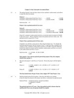
6.3) Consider the circuit in Fig. P6.3 with e(t) = 12sin(120
π
t) V, L = 0.0265mH. Find the value of R such that
the power in R is maximized ?
6.4) Consider the circuits in Fig. P6.4 where R = 100
Ω
, L = 100mH, C = 10
µ
F, e = 100sin(
ω
t) volts. Find i
R
(t),
i
L
(t), i
C
(t), V(t), the storage energy of the capacitor, the storage energy of the inductor, and the total
storage energy in 3 cases :
a)
ω
= 500 rad/s, b)
ω
= 1000 rad/s, c)
ω
= 2000 rad/s
Fig. P6.4
6.5) Consider the circuit in Fig. P6.5 where e = 100sin(
ω
t) volts, R = 100
Ω
, L = 100mH, C = 10
µ
F. Determine
i(t), v
R
(t), v
L
(t), v
C
(t), the storage energy of the capacitor U
C
(t), the storage energy of the inductor U
L
(t),
the average power of the resistor P
R
, the average power of the source P
e
in 3 cases :
a)
ω
= 500 rad/s, b)
ω
= 100 rad/s, c)
ω
= 1000 rad/s
Fig. P6.5 Fig. P6.6
6.6) Consider the circuit in Fig. P6.6 where R = 100
Ω
, C = 10
µ
F, e = 100sin(1000t) volts. The capacitor C has
circular plates of radius a, the space between the two plates is d = 0.1mm.
a) Find the voltage v and the current i.
Electricity and Magnetism
63
b) Find the electric field E, the magnetic field B and the displacement current i
d
between the capacitor
plates.
6.7) A typical “light dimmer” used to dim the stage lights in a theater consist of a variable inductor L
connected in series with the light bulb B as shown in the figure P6.7. The power supply is 220 V (rms) at
60 Hz; the light bulb is marked “220 V, 1000W”
a) What maximum inductance L is required if the power in the light bulb is to be varied by a factor of
five? Assume that the resistance of the light bulb is independent of its temperature?
b) Could one use a variable resistor instead of an inductor? If so, what maximum resistance is required?
Why isn’t this done?
Fig. P6.7
Homeworks 6
H6.1 Consider the circuits in Fig. H6.1 where e = 100sin(1000t) volts. Find i
R
(t), i
L
(t), i
C
(t), V(t), the storage
energy of the capacitor, the storage energy of the inductor, and the total storage energy (R in
Ω
, L in mH,
C in
µ
F).
Fig. H6.1 Fig. H6.2
n 1 2 3 4 5 6 7 8 9 10 11 12 13 14 15 16
R 100 100 100 100 100 100 100 100 100 100 100 100 100 100 100 100
L 5 10 20 40 60 80 100 120 150 175 200 225 250 275 300 350
C 10 10 10 10 10 10 10 10 10 10 10 10 10 10 10 10
n 17 18 19 20 21 22 23 24 25 26 27 28 29 30 31 32
R 200 200 200 200 200 200 200 200 200 200 200 200 200 200 200 200
L 5 10 20 40 60 80 100 120 150 175 200 225 250 275 300 350
C 5 5 5 5 5 5 5 5 5 5 5 5 5 5 5 5
n 33 34 35 36 37 38 39 40 41 42 43 44 45 46 47 48
R 50 50 50 50 50 50 50 50 50 50 50 50 50 50 50 50
L 5 10 20 40 60 80 100 120 150 175 200 225 250 275 300 350
C 20 20 20 20 20 20 20 20 20 20 20 20 20 20 20 20
Electricity and Magnetism
64
n 49 50 51 52 53 54 55 56 57 58 59 60 61 62 63 64
R 150
150
150
150
150
150
150 150 150 150 150 150 150 150 150 150
L 5 10 20 40 60 80 100 120 150 175 200 225 250 275 300 350
C 30 30 30 30 30 30 30 30 30 30 30 30 30 30 30 30
H6.2 Consider the circuits in Fig. H6.2 where e = 100sin(1000t) volts. Find i(t), the storage energy of the
capacitor, the storage energy of the inductor, and the total storage energy (R in
Ω
, L in mH, C in
µ
F).
n 1 2 3 4 5 6 7 8 9 10 11 12 13 14 15 16
R 100 100 100 100 100 100 100 100 200 200 200 200 200 200 200 200
L 25 50 75 100 125 150 175 200 25 50 75 100 125 150 175 200
C 10 10 10 10 10 10 10 10 10 10 10 10 10 10 10 10
n 17 18 19 20 21 22 23 24 25 26 27 28 29 30 31 32
R 100 100 100 100 100 100 100 100 200 200 200 200 200 200 200 200
L 25 50 75 100 125 150 175 200 25 50 75 100 125 150 175 200
C 5 5 5 5 5 5 5 5 5 5 5 5 5 5 5 5
n 33 34 35 36 37 38 39 40 41 42 43 44 45 46 47 48
R 100 100 100 100 100 100 100 100 200 200 200 200 200 200 200 200
L 25 50 75 100 125 150 175 200 25 50 75 100 125 150 175 200
C 20 20 20 20 20 20 20 20 20 20 20 20 20 20 20 20
n 49 50 51 52 53 54 55 56 57 58 59 60 61 62 63 64
R 100 100 100 100 100 100 100 100 200 200 200 200 200 200 200 200
L 25 50 75 100 125 150 175 200 25 50 75 100 125 150 175 200
C 15 15 15 15 15 15 15 15 15 15 15 15 15 15 15 15