EC&M’s Electrical Calculations Handbook - Chapter 2 pptx
Bạn đang xem bản rút gọn của tài liệu. Xem và tải ngay bản đầy đủ của tài liệu tại đây (243.19 KB, 13 trang )
Three-Phase Systems
Figure 2-1 shows the most common electrical system volt-
ages for 60-hertz (Hz) systems, and Fig. 2-2 shows the most
common electrical system voltages for 50-Hz systems. In
general, 60-Hz systems are designed to be in compliance
with Institute of Electrical and Electronics Engineers
(IEEE)/American National Standards Institute
(ANSI)/National Electrical Manufacturers Association
(NEMA)/National Electrical Code (NEC) requirements,
whereas, generally, 50-Hz systems are designed to be in com-
pliance with International Electrotechnical Commission
(IEC) or Australian standards. This book concentrates on 60-
Hz systems but notes 50-Hz system information where it is
pertinent. The immediate question arises as to how to select
the most correct voltage for a system that is being designed,
and the answer is equally straightforward and is shown in
the flowchart in Fig. 2-3. The ultimate goal of this flowchart
is to provide the load with proper current and voltage but not
to exceed approximately 2500 amperes (A) at any one bus
because of switchgear construction physical constraints.
In the simplest case of a single-phase circuit, an alter-
nating-current (ac) system consists of a generator, a load,
and conductors that connect them together. The generator is
Chapter
2
55
v
Copyright 2001 by The McGraw-Hill Companies, Inc. Click here for Terms of Use.
SYSTEM VOLTAGE Notes
115 Volt single-phase Note 1
115/230 Volt single-phase Note 2
120/208 Volt, 3-phase 4-wire wye Note 3
240 Volt, 3-phase, 3-wire delta Note 4
277/480 Volt, 3-phase 4-wire wye Note 5
460 Volt, 3-phase 3-wire delta Note 4
600/347 Volt, 3-phase, 4-wire wye
2400 Volt, 3-phase, 3-wire delta
2400 Coltm 3-phase, 4-wire wye
4160/2400 Volt, 3-phase, 4-wire wye
12470/7200 Volt, 3-phase, 4-wire wye Note 6
24940/14400 Volt, 3-phase, 4-wire wye Note 8
34500/19920 Volt, 3-phase, 4-wire wye Note 9
46000
69000
115000
138000
161000
230000
345000
500000
765000
Notes
1 Also known as 120 Volt, single-phase
2 Also known as 120/240 Volt, single-phase
3 "Professionally" referred to as 208Y/120 instead of as 120/208
4 This connection is not in frequent use any longer.
5 "Professionally" referred to as 480Y/277 or 460Y/265 instead of as 277/480
6 Actual voltage setting in this system may be from 12470 Volts to 13800 volts.
7 "Professionally" referred to as 600 Volts instead of 575 Volts.
8 "Professionally" referred to as 24940Y/14400 Volts.
9 "Professionally" referred to as 34500Y/19920 Volts
simply a coil of conductors by which a magnetic field is
passed repeatedly by rotating an electromagnet within the
coil. The voltage output of the generator is proportional to
the number of lines of magnetic flux that “cut” the coil, and
the number of lines of flux is governed by the amount of cur-
rent that flows through the electromagnet. Therefore, the
generator output voltage is regulated simply by increasing
or decreasing the “field” current through the electromagnet.
56 Chapter Two
Figure 2-1 This is a listing of the most common 60-Hz ac electrical
power system voltages.
From the generator to the load are two wires so as to form a
complete circuit, in addition to a “safety ground” conductor
that is run with, or encloses, the circuit conductors. Chapter
7 and article 250 of the National Electrical Code explain
when and how an ac system must be grounded.
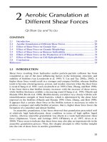
Figure 2-4 shows a generator and a motor with three single-
phase circuits that are entirely separate from one another.
Note that the voltage of each of these circuits originates in a
generator coil and that the load of each circuit is a motor coil
that consists of resistance and inductance. All three of these
coils are shown inside one generator housing within which one
electromagnet is spinning, known as the field. The generator
contains three single-phase systems, so it is called a three-
phase generator. The one voltage regulator provides regulated
field magnetic flux for all three phases simultaneously.
In a three-phase generator, the three phases are identi-
fied as phases a, b, and c. As the magnetic field piece rotates,
it passes first by phase coil a, then by phase coil b, and then
by phase coil c. Because of this action, the voltage is gener-
ated in coil a first, then in coil b, and finally in coil c, as
shown graphically in Fig. 2-5. Note that the voltage of one
phase is displaced from the voltage of the next phase by one-
third of a 360-electrical-degree rotation, or by 120 electrical
degrees. The figure also shows graphically how these volt-
ages can be shown as vectors, and it shows the relationship
of one voltage vector to the next.
Three-Phase Systems 57
SYSTEM VOLTAGE Notes
220 Volt single-phase Note 1
220/380 Volt 3-phase 4-wire wye Note 2
3300/1900 Volt, 3-phase 4-wire wye
6600/3800 Volt, 3-phase, 4-wire wye
11000/6350 Volt, 3-phase 4-wire wye
Notes
1 Also known as 230 Volt, single-phase
2 Also known as 400/230 Volt or 415/240 Volt single-phase
Figure 2-2 This is a listing of the most common 50-Hz ac
electrical power system voltages.
Wye-Connected Systems
Noting that the three vectors seem to form a semblance of
the letter Y, it is apparent that all three of these voltage vec-
tors begin at a “zero” or common point. This common point
is called the neutral point. In actuality, generators that are
connected in wye have one point of each of their windings
connected together and to ground, and the other ends of
each of the windings of phases a, b, and c are extended out
to the circuit loads, as shown in Fig. 2-6.
The voltage generated in one coil of the wye-connected
generator is known as the phase-to-ground voltage, or line-to-
58 Chapter Two
Figure 2-3 Use this logic to select the proper system voltage for an
electrical load.
ground voltage. Since any two different phase coils within
the generator are not displaced from one another by 180 elec-
trical degrees, their voltage vectors cannot be added without
considering their relative phase angle. Assuming that a gen-
erator coil voltage is 120 volts (V), Fig. 2-7 illustrates that
the phase-to-phase (or line-to-line) voltage is calculated as
120 ∠ 0° ϩ 120 ∠ 120° ϭ 120 (͙3
ෆ
) ϭ 120 (1.713) ϭ 208 V
This relationship is true for all wye connections: Phase-to-
phase voltage is equal to phase-to-neutral voltage multiplied
by 1.713.
Three-Phase Systems 59
Common voltages from wye-connected systems include
120/208, 277/480, 343/595, 2400/4160, and 7200/12,470 V.
Where these systems are grounded, the phase-to-neutral
voltage is also the phase-to-ground voltage.
Delta-Connected Systems
An even more straightforward method of connecting the
three phases together at the generator is known as the delta
connection, as illustrated in Fig. 2-8. In this connection, the
60 Chapter Two
RPM =
EQUIVALENT CIRCUIT FOR EACH
OF THE THREE PHASES.
N
S
3-PHASE GENERATOR 3-PHASE MOTOR
CALCULATE THE 2-POLE
GENERATOR RPM FOR
AN OUTPUT FREQUENCY
OF 60 HERTZ.
E
X
L
60 Hz
GENERATOR
R
120f
P
(120)(60)
RPM =
2
RPM = 3600 RPM
MOTOR
ARMATURE
motor
coil
inductance
motor
coil
resistance
RPM RPM
CALCULATE THE 2-POLE
MOTOR RPM FROM THIS
60 HERTZ SOURCE.
S
N
RPM =
RPM =
RPM = 3600 RPM
2
P
120f
(120)(60)
A 3-phase system consists of three 1-phase circuits.
CURRENT FLOW
Figure 2-4 Solve for generator rpm or motor rpm from frequency and
quantity of magnetic poles.
Figure 2-5
A graph of three ac voltages from a 60-Hz three-phase
generator.
61
N
S
3-PHASE GENERATOR
3-PHASE MOTOR
MOTOR
ARMATURE
RPM
RPM
S
N
Connections with motor load connected "in delta."
3-PHASE GENERATOR
Source-to-load external circuit connections.
3-PHASE MOTOR
a
b
c
Generator and motor coil interconnections.
Question: How would a "wye" generator be connected to a "delta" motor?
62
3-PHASE GENERATOR
S
RPM
N
S
3-PHASE MOTOR
MOTOR
ARMATURE
RPM
N
Note: The dotted wire is not needed because the neutral conductor in a
balanced "wye" (all three phases have the same load) carries no current.
Connections with motor load connected "in wye."
Source-to-load external circuit connections.
c
3-PHASE GENERATOR
3-PHASE MOTOR
b
a
Generator and motor coil interconnections.
Question: How would a "wye" generator be connected to a "wye" motor?
Figure 2-6
A wye three-phase system consists of three one-phase
circuits con-
nected together at a common neutral point that
is normally grounded, and
from the generator, connections can be made to
either wye or delta loads.
63
3-PHASE GENERATOR
3-PHASE MOTOR
a
b
c
Calculate the voltage across each delta-connected motor coil if
wye-connected generator coil voltage is 120 volts.
n
180 -j 104 = (180)
2
+ (104)
2
Minus Phase b voltage
- (120 120
°
= - 120 -60
°
)
= -(-120 COS 60 -j 120 SIN 60)
= -[(-120)(5) -j (120)(.866)]
= -[-60 +j 103.92]
Phase a voltage:
120
= 120 COS 0 + j 120 SIN 0
= [ (120)(1) +j (120)(0)]
0
°
= +60 -j 104
ARCTAN (- 0.577)
ARCTAN (-104/180)
= 180 -j 104
= 120 + j 0.0
+ 30
°
- 180
°
= 208
THEN CHANGE BACK TO POLAR FORM
Making a diagram of the circuit:
1. Diagram the system under analysis.
CALCULATE THE DIFFERENCE BETWEEN THE
VOLTAGE VECTORS IN RECTANGULAR FORM.
= 43199
= 208
-150
°
TOTAL VOLTS
64
phase a
phase b
phase c
120 volts 0°
120 volts 120°
2. Sketch generator coil
voltage vectors.
3. Sketch adding
voltage vectors.
phase a
120 volts 0
°
120 volts 120
°
phase b
120
°
Resultant vector.
4. Add voltage vectors.
Resultant vector.
120 volts -60
°
60
°
Note that the Tangent of 180
°
minus 120
°
, or 60
°
, also equals the 3 , which is 1.732
Therefore the phase-to-phase voltage in a "wye" equals coil voltage times 3.
Stated in another way, the phase-to-phase voltage equals the phase-to-neutral voltage times 3.
Applying this general finding in the problem stated above:
Phase-to-phase voltage = delta-connected motor coil voltage = Wye coil voltage times 3
Phase-to-phase voltage = (120) (1.732) = 208 Volts
65
Figure 2-7
Solve for motor coil voltage using vectors given
wye-connected genera-
tor coil voltage.
If a generator is
connected in “delta”
with a coil voltage of
460 volts, what is its
phase-to-phase
output voltage?
3-PHASE GENERATOR
3-PHASE GENERATOR
3-PHASE MOTOR
3-PHASE MOTOR
E
phase-to-phase
E
coil
E
coil
= 460V
= 460V
RPM
RPM
E
coil
= 460V
= 460V
S
N
S
N
MOTOR
ARMATURE
Figure 2-8
In a delta three-phase system, coil voltage is equal
to phase-to-phase
voltage.
66
end of one phase coil is connected to the end of the next
phase coil, and it is connected to the other end of the first
coil. The magnetic field effectively rotates within these
three coils, forming voltages that are 120 electrical degrees
apart, but with delta connections, the coil voltage is equal to
the line-to-line voltage.
Common voltages from delta-connected systems include
240, 460, and 2400 V. Where these systems are grounded,
the phase-to-ground voltages are unequal to one another,
thus creating extra considerations in the load circuits.
Three-Phase Systems 67