EC&M’s Electrical Calculations Handbook - Chapter 10 ppsx
Bạn đang xem bản rút gọn của tài liệu. Xem và tải ngay bản đầy đủ của tài liệu tại đây (327.94 KB, 24 trang )
Motors
Given that a very high percentage of the electrical loads in
the world are electric motors, this chapter pays specific
attention to design of electrical systems for these very
important loads. While there are many unique specific-duty
motors, the alternating-current (ac) squirrel-cage three-
phase induction motor is the primary “workhorse” of the
industry.
The rotor of an ac squirrel-cage induction motor consists
of a structure of steel laminations mounted on a shaft.
Embedded in the rotor is the rotor winding, which is a series
of copper or aluminum bars that are all short-circuited at
each end by a metallic end ring. The stator consists of steel
laminations mounted in a frame containing slots that hold
stator windings. These stator windings can be either copper
or aluminum wire coils or bars connected to the motor t-
leads that are brought out to the motor junction box.
Energizing the stator coils with an ac supply voltage causes
current to flow in the coils. The current produces an elec-
tromagnetic field that creates magnetic fields within the
stator. The magnetic fields vary in intensity, location, and
polarity as the ac voltage varies, thus creating a rotating
flux within the stator. The rotor conductors “cut” the stator
Chapter
10
285
v
Copyright 2001 by The McGraw-Hill Companies, Inc. Click here for Terms of Use.
flux, inducing current flow (and its own magnetic field)
within the rotor. The magnetic field of the stator and the
magnetic field of the rotor interact, causing rotation of the
rotor and motor shaft. This action causes several motor
characteristics, such as rotating speed (given in revolutions
per minute), motor torque, motor horsepower, motor start-
ing current, motor running current, and motor efficiency.
Selecting Motor Characteristics
Motor voltage
The power supply to motors can be either single-phase or
three-phase, where single-phase is normally applied to
motors having nameplate ratings of less than 1 horsepower
(hp) and three-phase for larger motors.
Single-phase power is always 120 volts (V), and it is gen-
erally used to supply motors no larger than
1
ր
3
hp. Three-
phase voltage sources of 208, 240, 480, and 600 V are,
respectively, normally applied to motors having nameplate
ratings of 200, 230, 460, and 575 V to offset voltage drop in
the line. This is especially important where torque is of con-
cern because torque is a function of the square of the voltage
(decreasing the applied voltage to 90 percent decreases
torque to 81 percent).
Motor speed
The speed of a motor is determined mainly by the frequen-
cy of the source voltage and the number of poles built into
the structure of the winding. With a 60-hertz (Hz) power
supply, the possible synchronous speeds are 3600, 1800,
1200, and 900 revolutions per minutes (rpm), and slower.
Induction motors develop their torque by operating at a
speed that is slightly less than synchronous speed.
Therefore, full-load speeds for induction motors are, respec-
tively, approximately 3500, 1750, 1160, and 875 rpm. Motors
whose coils can be connected as two-pole, four-pole, or six-
pole coils, for example, can have their speeds changed mere-
ly by switching pole wiring connections.
286 Chapter Ten
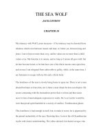
The speed (in rpm) at which an induction motor operates
depends on the speed of the stator rotating field and is
approximately equal to 120 times the frequency (f) divided
by the quantity of magnetic poles (P) in the motor stator
minus the rotor slip. Every induction motor must have some
slip to permit lines of stator flux to cut the rotor bars and
induce rotor current; therefore, no induction motor can oper-
ate at exactly synchronous speed (120f/P). The more heavily
the motor is loaded, the greater the slip. Thus, the greater
the voltage, the less is the slip. Figure 10-1 shows a typical
motor speed calculation.
Ambient temperature and humidity
The ambient conditions must be considered in selecting the
type of motor to be used in a specific location. Ambient tem-
perature is the temperature of the air surrounding the
motor. If it is very hot, special lubricant that does not
decompose or “coke” at elevated temperatures and special
Motors 287
Figure 10-1 Solve for motor synchronous speed given frequency, quantity
of magnetic poles in the motor, and type of motor.
wire insulation normally are required. Locations where high
moisture levels or corrosive elements also exist require spe-
cial motor characteristics, such as two-part epoxy paint,
double-dip paint processes, and waterproof grease.
Standard motors are designed to operate in an ambient tem-
perature of up to 40°C (104°F) and normally are lubricated
with high-temperature grease. At altitudes of greater than
3300 feet (ft), the lower density of the air reduces the self-
cooling ability of the motor; therefore, compensation for alti-
tude as well as ambient temperature must be made.
Additional information about altitude compensation is pro-
vided below under the heading “Service Factor.”
Torque
The rotating force that a motor develops is called torque. Due
to the physical laws of inertia, where a body at rest tends to
remain at rest, the amount of torque necessary to start a load
(starting torque) is always much greater than the amount of
torque required to maintain rotation of the load after it has
achieved normal speed. The more quickly a load must accel-
erate from rest to normal rotational speed, the greater must
be the torque capability of the motor driver. For very large
inertia loads or loads that must be accelerated quickly, a
motor having a high starting torque should be applied.
The National Electrical Manufacturers Association
(NEMA) provides design letters to indicate the torque, slip,
and starting characteristics of three-phase induction
motors. They are as follows:
Design A is a general-purpose design used for industrial
motors. This design exhibits normal torques and full-load
slip of approximately 3 percent and can be used for many
types of industrial loads.
Design B is another general-purpose design used for
industrial motors. This design exhibits normal torques
while also having low starting current and a full-load slip
of approximately 3 percent. This design also can be used
for many types of industrial loads.
288 Chapter Ten
Design C motors are characterized by high starting
torque, low starting current, and low slip. Because of its
high starting torque, this design is useful for loads that
are hard to start, such as reciprocating air compressors
without unloader kits.
Design D motors exhibit very high starting torque, very
high slip of 5 to 13 percent, and low starting current.
These motors are excellent in applications such as oilfield
pumping jacks and punch presses with large flywheels.
Variable-torque motors exhibit a speed-torque character-
istic that varies as the square of the speed. For example, a
two-speed 1800/900-rpm motor that develops 10 hp at 1800
rpm produces only 2.5 hp at 900 rpm. Variable-torque
motors are often a good match for loads that have a torque
requirement that varies as the square of the speed, such as
blowers, fans, and centrifugal pumps.
Constant-torque motors can develop the same torque at
each speed; thus power output from these motors varies
directly with speed. For example, a two-speed motor rated
at 10 hp at 1800 rpm would produce 5 hp at 900 rpm. These
motors are useful in applications with constant-torque
requirements, such as mixers, conveyors, and positive-dis-
placement compressors.
Service factor
The service factor shown on a motor nameplate indicates the
amount of continuous overload to which the motor can be
subjected at nameplate voltage and frequency without dam-
aging the motor. The motor may be overloaded up to the
horsepower found by multiplying the nameplate-rated
horsepower by the service factor.
As mentioned earlier, service factor also can be used to
determine if a motor can be operated continuously at alti-
tudes higher than 3300 ft satisfactorily. At altitudes greater
than 3300 ft, the lower density of air reduces the motor’s
cooling ability, thus causing the temperature of the motor to
be higher. This higher temperature can be compensated for,
Motors 289
in part, by reducing the effective service factor to 1.0 on
motors with a 1.15 (or greater) service factor.
Motor enclosures
The two most common types of enclosures for electric motors
are the totally enclosed fan-cooled (TEFC) motor and the
open drip-proof (ODP) motor. The TEFC motor limits
exchange of ambient air to the inside of the motor, thus
keeping dirt and water out of the motor, whereas the ODP
motor allows the free exchange of air from the surrounding
air to the inside of the motor. Other types include the total-
ly enclosed nonventilated (TENV), the totally enclosed air
over (TEAO), and the explosionproof enclosure. Selection of
the enclosure is determined by the motor environment.
Winding insulation type
The most common insulation classes used in electric motors
are class B, class F, and class H. Motor frame size assign-
ments are based on class B insulation, where, based on a
40°C ambient temperature, class B insulation is suitable for
an 80°C temperature rise. Also based on a 40°C ambient
temperature, class F insulation is suitable for a 105°C rise,
and class H insulation is suitable for a 125°C rise. Using
class F or class H insulation in a motor that is rated for a
class B temperature rise is one way to increase the service
factor or the motor’s ability to withstand high ambient tem-
peratures. Also, these insulations incorporate extra capabil-
ity for localized “hot spot” temperatures.
Efficiency
Efficiency of an appliance is defined as the measure of the
input energy to the output energy. The efficiency of an elec-
tric motor is the usable output power of the motor divided by
the input power to the motor, and the differences between
input and output power are losses in the motor. Smaller
motors generally are less efficient than larger motors, and
motors operated at less than half load usually are inefficient
290 Chapter Ten
compared with their operation at full load. Therefore, for
maximum operating efficiency, motors should be selected
such that their nameplate horsepower or kilowatt rating is
nearly the same as the driven load.
All the operating characteristics of a motor are interde-
pendent, as shown in Fig. 10-2. A summary of these charac-
teristics is provided in Fig. 10-2 to assist in expediting
proper motor selection.
Motor starting current
When typical induction motors become energized, a much
larger amount of current than normal operating current
rushes into the motor to set up the magnetic field surround-
ing the motor and to overcome the lack of angular momen-
tum of the motor and its load. As the motor increases to slip
speed, the current drawn subsides to match (1) the current
required at the supplied voltage to supply the load and (2)
losses to windage and friction in the motor and in the load
and transmission system. A motor operating at slip speed
and supplying nameplate horsepower as the load should
draw the current printed on the nameplate, and that cur-
rent should satisfy the equation
Horsepower ϭ
voltage ϫ current ϫ
power factor ϫ motor efficiency ϫ ͙3
ෆ
746
Typical induction motors exhibit a starting power factor of
10 to 20 percent and a full-load running power factor of 80
to 90 percent. Smaller typical induction motors exhibit an
operating full-load efficiency of approximately 92 percent,
whereas large typical induction motors exhibit an operating
full-load efficiency of approximately 97.5 percent.
Since many types of induction motors are made, the
inrush current from an individual motor is important in
designing the electrical power supply system for that motor.
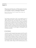
For this purpose, the nameplate on every motor contains a
code letter indicating the kilovoltampere/horsepower start-
ing load rating of the motor. A table of these code letters and
Motors 291
Figure 10-2
Solve for motor torque, speed, power factor, and
efficiency reac-
tions to varying voltage above and below nameplate
voltage rating.
292
their meanings in approximate kilovoltamperes and horse-
power is shown in Fig. 10-3. Using these values, the inrush
current for a specific motor can be calculated as
I
inrush
ϭ
An example of this calculation for a 50-hp code letter G
motor operating at 460 V is shown in Fig. 10-4.
Because of the items listed above, motors that produce
constant kilovoltampere loads make demands on the elec-
trical power system that are extraordinary compared with
the demands of constant kilowatt loads. To start them, the
overcurrent protection system must permit the starting cur-
rent, also called the locked-rotor current, to flow during the
normal starting period, and then the motor-running over-
current must be limited to approximately the nameplate
full-load ampere rating. If the duration of the locked-rotor
code letter value ϫ horsepower ϫ 577
ᎏᎏᎏᎏᎏ
voltage
Motors 293
CODE
LETTER
ON
MOTOR
NAMEPLATE
A 0 1.57 3.14
B 3.15 3.345 3.54
C 3.55 3.77 3.99
D 4 4.245 4.49
E 4.5 4.745 4.99
F 5 5.295 5.59
G 5.6 5.945 6.29
H 6.3 6.695 7.09
J 7.1 7.545 7.99
K 8 8.495 8.99
L 9 9.495 9.99
M 10 10.595 11.19
N 11.2 11.845 12.49
P 12.5 13.245 13.99
R 14 14.995 15.99
S 16 16.995 17.99
T 18 18.995 19.99
U 20 29.2 22.39
V 22.4 NO LIMIT
KVA PER
HORSEPOWER
WITH LOCKED
ROTOR
MINIMUM
KVA PER
HORSEPOWER
WITH LOCKED
ROTOR
MEAN VALUE
KVA PER
HORSEPOWER
WITH LOCKED
ROTOR
MAXIMUM
Figure 10-3 Solve for the kilovoltampere/horsepower value given
motor code letter.
294 Chapter Ten
Starting currents exhibited by large induction motors are so much
greater than those for smaller motors that starting voltage dip is a
concern.
Figure 10-4 Solve for inrush current of a 50-hp code letter G motor oper-
ating at 480 V, three-phase.
current is too long, the motor will overheat due to I
2
R heat
buildup, and if the long-time ampere draw of the motor is
too high, the motor also will overheat due to I
2
R heating.
The National Electrical Code provides limitations on both
inrush current and running current, as well as providing a
methodology to determine motor disconnect switch ampere
and horsepower ratings.
Table 430-152 of the National Electrical Code provides the
maximum setting of overcurrent devices upstream of
the motor branch circuit, and portions of this table are
replicated in Fig. 10-5. The code provides motor running
current for typical three-phase induction motors in Table
430-150, portions of which are replicated in Fig. 10-6, and
it provides motor disconnect switch horsepower and ampere
criteria in Table 430-151, portions of which are replicated
in Fig. 10-7 on pp. 298 and 299.
Calculating Motor Running Current
The following figures illustrate the calculations required by
specific types of motors in the design of electric circuits to
permit these loads to start and to continue to protect them
during operation:
Motors 295
Figure 10-5 Replication of NEC Table 430-152 of maximum overcurrent
protective devices for motor circuits. Solve for overcurrent device rating
for motor branch circuit given table ampere load.
Figure 10-8: Continuous-duty motors driving a continu-
ous-duty load (pp. 300 and 301)
Figure 10-9: Continuous-duty motors driving an inter-
mittent-duty load (pp. 302 and 303)
Figure 10-10: Continuous-duty motors driving a periodic-
duty load (pp. 304 and 305)
Figure 10-11: Continuous-duty motors driving a varying-
duty load (pp. 306 and 307)
Calculating Motor Branch-Circuit
Overcurrent Protection and Wire Size
Article 430-52 of the National Electrical Code specifies that
the minimum motor branch-circuit size must be rated at 125
percent of the motor full-load current found in Table 430-
150 for motors that operate continuously, and Section 430-
32 requires that the long-time overload trip rating not be
296 Chapter Ten
HORSEPOWER 208 VOLTS 230 VOLTS 460 VOLTS 575 VOLTS
0.5 2.4 2.2 1.1 0.9
0.75 3.5 3.2 1.6 1.3
1 4.6 4.2 2.1 1.7
1.5 6.6 6 3 2.4
2 7.5 6.8 3.4 2.7
3 10.6 9.6 4.8 3.9
5 16.7 15.2 7.6 6.1
7.5 24.2 22 11 9
10 30.8 28 14 11
15 46.2 42 21 17
20 59.4 54 27 22
25 74.8 68 34 27
30 88 80 40 32
40 114 104 52 41
50 143 130 65 52
60 169 154 77 62
75 211 192 96 77
100 273 248 124 99
125 343 312 156 125
150 396 360 180 144
200 528 480 240 192
Figure 10-6 Table of full-load currents for three-phase ac induction
motors.
greater than 115 percent of the motor nameplate current
unless the motor is marked otherwise. Note that the values
of branch-circuit overcurrent trip (the long-time portion of a
thermal-magnetic trip circuit breaker and the fuse melt-out
curve ampacity) are changed by Table 430-22b for motors
that do not operate continuously.
Motors 297
298
Figure 10-7
Solve for the horsepower rating of motor disconnecting
means
using both horsepower and locked-rotor current.
299
300
Figure 10-8
Solve for the wire ampere rating required for a
continuous-duty ac
motor driving a continuous load.
301
302
Figure 10-9
Solve for the wire ampere rating required for a
continuous-duty ac
motor driving an intermittent-duty load.
303
304
Figure 10-10
Solve for the wire ampere rating required for
a continuous-duty ac
motor driving a periodic-duty load.
305
306
Figure 10-11
Solve for the wire ampere rating required for
a continuous-duty
ac motor driving a varying-duty load.
307
Figure 10-12
Select the correct motor characteristics for the
driven load from
this chart.
308