Kinetics of Materials - R. Balluff_ S. Allen_ W. Carter (Wiley_ 2005) Episode 7 ppt
Bạn đang xem bản rút gọn của tài liệu. Xem và tải ngay bản đầy đủ của tài liệu tại đây (3.02 MB, 45 trang )
CHAPTER
11
MOTION
OF
DISLOCATIONS
The motion
of
dislocations by glide and climb is fundamental to many important
kinetic processes in materials. Gliding dislocations are responsible for plastic defor-
mation of crystalline materials at relatively low temperatures, where any dislocation
climb is negligible. They also play important roles in the motion of glissile interfaces
during twinning and diffusionless martensitic phase transformations. Both gliding
and climbing dislocations cause much
of
the deformation that occurs at higher tem-
peratures where self-diffusion rates become significant, and significant climb is then
possible.
Climbing dislocations act as sources and sinks for point defects. This
chapter establishes some of the basic kinetic features of both dislocation glide and
climb.
11.1
GLIDE AND CLIMB
The general motion of a dislocation can always be broken down into two compo-
nents: glide motion and climb motion.
Glide
is movement of the dislocation along
its glide (slip) plane, which is defined as the plane that contains the dislocation line
and its Burgers vector.
Climb
is
motion normal to the glide plane. Glide motion is
a conservative process in the sense that there is no need to deliver or remove atoms
at the dislocation core during its motion. In contrast, the delivery or removal
of
atoms at the core is necessary for climb. This is illustrated for the simple case
of
the
glide and climb of an edge dislocation in Fig.
11.1,
The glide along
IC
in Fig.
11.1
a
and
b
is accomplished by the local conservative shuffling of atoms at the disloca-
Kinetics
of
Materials.
By Robert
W.
Balluffi, Samuel
M.
Allen, and
W.
Craig Carter.
253
Copyright
@
2005
John Wiley
&
Sons, Inc.
254
CHAPTER
11:
MOTION
OF
DISLOCATIONS
.&.
0
0
@
(b)
Y
t
Figure
11.1:
Glide and climb of edge dislocation in primitive cubic crystal
(g
=
[boo].
(
=
[OOl])
[l].
(a)
and
(b)
Glide from left to right.
(c)-(f)
Downward climb along
-y.
In
(d), the lighter-shaded substitutional atom shown adjacent to the dislocation core in (c)
has joined the extra half plane and created a vacancy. In (e), the vacancy has migrated
away from the dislocation core by diffusion. In
(f),
the vacancy has been annihilated at the
surface step. This overall process is equivalent to removing an atom from the surface and
transporting it to the dislocation at its core.
A
new site was created at the dislocation, which
acted as a vacancy source. This site was subsequently annihilated at the surface. which acted
as an atom source.
tion core as it moves. The climb along
-y,
however, requires that the extra plane
associated with the edge dislocation be extended in the
-y
direction. This requires
a diffusive flux of atoms to the dislocation core, and when self-diffusion occurs by
a vacancy mechanism, the corresponding creation of an equivalent number of new
lattice sites in the form
of
vacancies. In this case, the dislocation acts as a sink for
atoms and, equivalently,
as
a source for vacancies. Glide can therefore occur at any
temperature, whereas significant climb is possible only at elevated temperatures
where the required diffusion can 0ccur.l
Defects such as dislocations can be sources or sinks for atoms or for vacancies.
Whether such point entities are created or destroyed depends on the type of defect,
its orientation, and the stresses acting on
it.
It is convenient to adopt
a
single term
source,
which describes a defect’s capability for creation and destruction of crystal
sites and vacancies in the crystal. “Source” will generically indicate creation of
point entities (i.e., “positive” source action)
as
well
as
destruction of point entities
(i.e., “negative” source action). Thus, a climbing edge dislocation that destroys
vacancies will be, equivalently, both a (positive) source of atoms and a (negative)
source of vacancies. If the sense of climb is reversed, the dislocation would be a
(negative) source of atoms.
lProvided that the Peierls force is not too
large
(see Section
11.3.1).
11
2.
DRIVING
FORCES
ON
DISLOCATIONS
255
11.2 DRIVING FORCES
ON
DISLOCATIONS
Dislocations in crystals tend to move in response to forces exerted on them. In gen-
eral, an effective driving force is exerted
on
a dislocation whenever a displacement
of the dislocation causes a reduction in the energy of the system. Forces may arise
in a variety of ways.
11.2.1
Mechanical
Force
In general, a segment of dislocation in
a
crystal in which there is a stress field is
subjected to an effective force because the stress does an increment of work (per
unit length),
bW,
when the dislocation is moved in a direction perpendicular to
itself by the vector,
67.
In this process, the material on one side of the area swept
out by the dislocation during its motion is displaced relative to the material on the
opposite side by the Burgers vector,
b',
of the dislocation. Work
bW
is generally done
by the stress during this displacement. This results in a corresponding reduction
in the potential energy
of
the system. The magnitude of the effective force on
the dislocation (often termed the "mechanical" force) is then just
f
=
bW/br.
A
detailed analysis of this force yields the Peach-Koehler equation:
(11.1)
where
L
is the mechanical force exerted on the dislocation (per unit length),
u
the
stress tensor in the material at the dislocation, and
(
the unit vector tangent to
the dislocation along its positive direction
[2].
Equation 11.1 is consistent with the
convention that the Burgers vector of the dislocation
is
the closure failure (from
start to finish) of a Burgers circuit taken in a crystal in a clockwise direction around
the dislocation while looking along the dislocation in the positive direction.2 When
written in full, Eq. 11.1 has the form
where
(11.2)
(11.3)
With this result, the mechanical force exerted on any straight dislocation by
any stress field can be calculated. For example, if the edge dislocation
(b'
=
[boo],
(
=
[OOl])
in Figure
11.1
is subjected to a shearing stress
uxy,
it experiences a force
urging it to glide on its slip plane in the
2
direction. However,
if
the dislocation is
subjected to the tensile stress,
gxx,
Eq.
11.1
shows that it will experience the force
f,,
=
-jbaxx
(i.e., a force urging it to climb in the
-9
direction).
In a more general stress field, the force (which is always perpendicular to the
dislocation line) can have a component in the glide plane
of
the dislocation as well
as a compor!ent normal to the glide plane. In such a case, the overall force will
tend to produce both glide and climb. However, if the temperature is low enough
that no significant diffusion is possible, only glide will occur.
2The Burgers circuit
is
constructed
so
that it will close if mapped step
by
step into
a
perfect
reference crystal.
See
Hirth and Lothe
[2].
.+
256
CHAPTER
11
MOTION
OF
DISLOCATIONS
11.2.2
Osmotic
Force
A
dislocation is generally subjected to another type of force if nonequilibrium point
defects are present (see Fig.
11.2).
If the point defects are supersaturated vacancies,
they can diffuse to the dislocation and be destroyed there by dislocation climb.
A
diffusion flux of excess vacancies to the dislocation is equivalent to an opposite flux
of atoms taken from the extra plane associated with the edge dislocation. This
causes the extra plane to shrink, the dislocation to climb in the
fy
direction, and
the dislocation to act
as
a vacancy sink. In this situation, an effective “osmotic”
force is exerted on the dislocation in the
fy
direction, since the destruction of the
excess vacancies which occurs when the dislocation climbs a distance
by
causes the
free energy of the system to decrease by
66.
The osmotic force is then given by
By evaluating
66
and
by
when
SNv
vacancies are destroyed, an expression for
f;.
can be obtained. The quantity
66
is just
-pvGNv,
where the chemical potential
of the vacancies,
pv,
is given by Eq.
3.66.
If a climbing edge dislocation destroys
SNv
vacancies per unit length, the climb distance will be
by
=
(R/b)bNv.
The
osmotic force is therefore
f;.
=
-j
66lSy.
(11.4)
This result is easily generalized for mixed dislocations which are partly screw-
type and partly edge-type, and also for cases having subsaturated vacancies. For a
mixed dislocation,
b
must be replaced by the edge component of its Burgers vector
Figure
11.2:
Oblique view of edge dislocation climb due to destruction of excess
vacancies. The extra plane associated with the edge dislocation
is
shaded. At
A,
a vacancy
from the crystal is destroyed directly at a jog. At
B,
a vacancy from the crystal jumps
into the core. At
C,
an attached vacancy is destroyed at a jog. At
D,
an attached vacancy
diffuses along the core.
11
2
DRIVING
FORCES
ON
DISLOCATIONS
257
and the result (see Exercise
11.1)
is
where
-
-kT
R
B
=
b
-
In
($)
(11.5)
(11.6)
If the vacancies are subsaturated, the dislocation tends to produce vacancies and
therefore acts as a vacancy source. In that case, Eq. 11.5 will still hold, but
pv
will
be negative and the climb force and climb direction will be reversed. Equation 11.5
also holds for interstitial point defects, but the sign of
6
will be reversed.
11.2.3
Curvature Force
Still another force will be present if a dislocation is curved. In such cases, the
dislocation can reduce the energy of the system by moving to decrease its length.
An effective force therefore tends to induce this type of motion. Consider, for
example, the simple case of a circular prismatic dislocation loop of radius,
R.
The
energy of such a loop is
W=R-
2(1 pb2
-
u)
[In(:)
-
11
(11.7)
where
R,
is the usual cutoff radius (introduced to avoid any elastic singularity at
the origin)
[2].
The energy of such a loop can be reduced by reducing its radius
and therefore its length. Thus, a climb force,
fl;,
exists which is radial and in the
direction to shrink the loop.
A
calculation of the reduction in the loop energy
achieved when its radius shrinks by
6R
shows that
(dW/dR) 6R
=
27rR
fK
6R.
The
force is therefore
(11.8)
This result may be generalized. Any segment of an arbitrarily curved dislocation
line will be subjected to a curvature force of similar magnitude because the stress
fields of other segments of the dislocation line at some distance from the segment
under consideration exert only minimal forces on it. For most curved dislocation
geometries, the magnitude of the right-hand side of Eq. 11.8 is approximately equal
to
pb2
(l/R).
Therefore, for a general dislocation with radius of curvature,
R,
(11.9)
The quantity
pb2
has the dimensions of a force (or, equivalently, energy per unit
length) and is known as the
line tension
of the dislocation. Equation 11.9 can also
be obtained by taking the line tension to be a force acting along the dislocation
in a manner tending to decrease its length.3 This approximation is supported by
detailed calculations for other forms of curved dislocations
[2].
3This
is
explored further
in
Exercise
11.2.
258
CHAPTER
11:
MOTION
OF
DISLOCATIONS
The vector form of Eq.
11.9
is readily obtained. If r'is the position vector tracing
out the dislocation line in space and
ds
is the increment of arc length traversed along
the dislocation when
r'
increased by
dr',4
(11.10)
where at the point
r'
on the line,
fi
is the
principal normal,
which is a unit vector
perpendicular to
(
and directed toward the concave side of the curved line,
K
is the
curvature, and
R
is the radius of curvature. Therefore,
(11.11)
11.2.4
The total driving force on a dislocation,
f:
is the sum of the forces previously
Total Driving Force on a Dislocation
considered and, therefore,
$=flr+$+.L
=
(IX
t)
+
11.3
DISLOCATION GLIDE
df
4
x
B
+
pb2
-
=
x
(2
-
4
+
pb2
-
(11.12)
('
'>
ds
ds
Of central interest is the rate at which a dislocation is able to glide through a
crystal under a given driving force. Many factors play potential roles in determining
this rate. In perfect crystals, relativistic effects can come into play as dislocation
velocities approach the speed of sound in the medium. At elevated temperatures,
dissipative phonon effects can produce frictional drag forces opposing the motion.
Also, the atom shuffling at the core, which is necessary for the motion, may be
difficult in certain types of crystals and thus inhibit glide. In imperfect crystals,
any point, line, and planar defects and inclusions can serve as additional obstacles
hindering dislocation glide. We begin by discussing glide in a perfect single crystal,
which for the present is taken to be a linear elastic continuum.
11.3.1
Relativistic Effects.
Consider the relatively simple case of a screw dislocation mov-
ing along
5
at the constant velocity
v'
(see Fig. 11.3). The elastic displacements,
ul,
u2,
and
213,
around such a dislocation may be determined by solving the Navier
equations of isotropic linear elasticity [3].5 For this screw dislocation, the only non-
zero displacements are along
z,
and for the moving dislocation the Navier equations
Glide in Perfect Single Crystals
therefore reduce to
(11.13)
where
p
is the density of the medium,
p
is the shear modulus, and on the left is
the inertial term due to the acceleration of mass caused by the moving dislocation.
4See Appendix
C
for
a
brief
survey
of mathematical relations for curves and surfaces.
5See standard references on dislocation mechanics
[2,
4,
51.
11
3
DISLOCATION
GLIDE
259
Y
Y‘
i
A
I
Figure
11.3:
=
[OOl]
moving in the
+z
direction
at
a constant velocity
v’.
The origin
of
the primed
(d,
y’,
z’)
coordinate system is fixed to the
niovi
ng
dislocation.
Screw dislocation with
b’
=
[OOb],
Equation
11.13
is readily solved after making the changes of variable
I
-
r-vt
x
yL
E
7-
Y’
=
Y
2‘
=
z
I
-
t-vx
(11.14)
where
c
=
is the velocity of a transverse shear sound wave in the elastic
medium. The origin of the
(XI,
y‘,
z’)
coordinate system is fixed on the moving
dislocation as in Fig.
11.3.
These changes of variable transform Eq.
11.13
into
d2u3
32213
-++,=o
dXl2
dy
(11.15)
because
ug
is a not
a
function of
tl
in the moving coordinate system and
du3/dt’
=
0.
Equation 11.15 has the form of the Navier equation for a static screw dislocation
and its solution6 has the form
2.n
Transforming this solution back to
x,
y,
t
space,
b
2i7
uz(x,
y,
t)
=
-
tan-
(1
1.16)
(11.17)
The shear stress of the dislocation in cylindrical coordinates,
goz,
may now be
found by using the standard relations
orz
=
p(au,/dx),
uyz
=
p(du,/dy),
and
Ooz
=
oyz
cose
-
ozz
sine. The result is
pb
YL
(x;
+
yg)’”
goz
=
-
2.n
x;+r;y;
6Further discussion of this can
be
found in
Hirth
and Lothe
[2].
(11.18)
260
CHAPTER
11:
MOTION
OF
DISLOCATIONS
where the distances
20
and yo (measured from the moving dislocation) have been
introduced. Equation
11.18
indicates that the stress field is progressively contracted
along the
20
axis and extended along the yo axis as the velocity
of
the dislocation is
increased. This distortion is analogous to the Lorentz contraction and expansion of
the electric field around
a
moving electron, and the quantity
y~
plays a role similar
to the Lorentz-Einstein term
(1
-
w2/c2)lI2
in the relativistic theory of the electron,
where
c
is the velocity of light rather than of a transverse shear wave. In the limit
when
w
+
c
and
y~
-+
0,
the stress around the dislocation vanishes everywhere
except along the y'-axis, where it becomes infinite.
Another quantity of interest is the velocity dependence of the energy of the
dislocation. The energy density in the material around the dislocation,
w,
is the
sum
of
the elastic strain-energy density and the kinetic-energy density,
w
=
2w,,
2
+
2pLEyz
+
zp
(;;)2=;[(EE)2+(L!%)2+;(a,'l
-
(1
1.19)
where the first two terms in each expression make up the elastic strain-energy
density and the third term is the kinetic-energy density
[3].
The total energy may
then be found by integrating the energy density over the volume surrounding the
(11.20)
where
W"
is the elastic energy
of
the dislocation per unit length at rest [2,
4,
51,
(1
1.21)
Here,
R,
is again the usual cutoff radius at the core and
R
is the dimension of
the crystal containing the dislocation. According to Eq. 11.20, the energy of the
moving dislocation will approach infinity as its velocity approaches the speed of
sound. Again, the relationship for the moving dislocation is similar to that for a
relativistic particle as
it
approaches the speed of light.
These results indicate that in the present linear elastic model, the limiting ve-
locity for the screw dislocation will be the speed of sound as propagated by a
shear wave. Even though the linear model will break down as the speed of sound
is approached, it is customary to consider
c
as the limiting velocity and to take
the relativistic behavior as a useful indication of the behavior of the dislocation as
w
+
c.
It is noted that according to Eq. 11.20, relativistic effects become important
only when
w
approaches
c
rather closely.
The behavior of an edge dislocation is more complicated since its displacement
field produces both shear and normal stresses. The solution consists of the super-
position of two terms, each of which behave relativistically with limiting velocities
corresponding to the speed
of
transverse shear waves and longitudinal waves, re-
spectively
[a,
4,
51.
The relative magnitudes of these terms depend upon
w.
Drag
Effects.
Dislocations gliding in real crystals encounter dissipative frictional
forces which oppose their motion. These frictional forces generally limit the dislo-
cation velocity to values well below the relativistic range. Such drag forces originate
from
a
variety of sources and are difficult to analyze quantitatively.
11.3:
DISLOCATION
GLIDE
261
Drag
by
Emission
of
Sound Waves.
When
a
straight dislocation segment glides in
a crystal, its core structure varies periodically with the periodicity of the crystal
along the glide direction. The potential energy of the system,
a
function of the core
structure, will therefore vary with this same periodicity
as
the dislocation glides.
Because of this position dependence, there is
a
spatially periodic
Peierls
force
that
must be overcome to move
a
dislocation. Therefore, the force required to displace
a
dislocation continuously must exceed the Peierls force, indicated by the positions
where the derivative of potential energy in Fig.
11.4
is maximal
[2].’As
the dislocb
tion traverses the potential-energy maxima and minima, it alternately decelerates
and accelerates and changes its structure periodically in
a
“pulsing” manner. These
structural changes radiate energy in the form of sound waves (phonons). The energy
required to produce this radiation must come from the work done by the applied
force driving the dislocation. The net effect is the conversion of work into heat, and
a
frictional drag force is therefore exerted on the dislocation.
I
I
b
X
Position
of
dislocation
Figure
11.4:
Variation
of
potential energy
of
crystal plus dislocation
w
a
function
of
dislocation position. Periodicity
of
potential energy corresponds to periodicity
of
crystal
structure.
In
a
crystal, sound waves of
a
given polarization and direction of propagation
are dispersive-their velocity is
a
decreasing function of their wavenumber, which
produces
a
further drag force on a dislocation. The dispersion relation is
(11.22)
where
w
is the angular frequency,
d
is the distance between successive atomic planes
in the direction of propagation,
k
=
27r/X
is the wavenumber, and
X
is the wave-
length.8 In the long-wavelength limit
(A
>>
d)
corresponding to an elastic wave
in
a
homogeneous continuum, the phase velocity
is
c
(as
expected). However,
at
the shortest wavelength that the crystal can transmit
(A
=
24,
the phase veloc-
ity is lower and, according to Eq.
11.22,
is given by
2c/7r.
The displacement field
of the dislocation can now be broken down into Fourier components of different
wavelengths. If the dislocation
as
a
whole is forced to travel
at
a velocity lower
than
c
but higher than
2c/7r,
the short-wavelength components will be compelled
to travel faster than their phase velocity and will behave
as
components of a su-
‘However, dislocations will still move by thermally activated processes below the Peierls force.
*For
more about the dispersion relation,
see
a reference
on
solid-state physics, such
as
Kittel
[6].
262
CHAPTER
11:
MOTION
OF
DISLOCATIONS
I<,,,
IIIII
IIIII
IIIII
IIIII
IIIII
IIIII
IIIII
IIIII
IIIII
IIIII
IIIII
IIIII
IIIII
IIIII
IIIII
IIIII
IIIII
IIIII
IIIII
IIIII
personic dislocation. These components will radiate energy and therefore impose a
viscous drag force on the dislocation (see Section 11.3.4).
Drag
by
Scattering
of
Phonons and Electrons.
A
dislocation scatters phonons by
two basic mechanisms. First, there are density changes in its displacement field
which produce scattering. Second, the dislocation moves under the influence of an
impinging sound wave and, as
it
oscillates, re-radiates a cylindrical wave. If the
dislocation undergoes no net motion and is exposed to an isotropic flux of phonons
it will experience no net force. However,
if
it is moving, the asymmetric phonon
scattering will exert a net retarding force, since, in general, any entity that scatters
plane waves experiences a force in the direction of propagation of the waves. If, in
addition, free electrons are present, they will be scattered by an effective scattering
potential produced by the displacement field of the dislocation. This produces a
further retarding force on a moving dislocation.
Peierls Force: Continuous
vs.
Discontinuous Motion.
In some crystals (e.g., covalent
crystals) the Peierls force may be
so
large that the driving force due to the applied
stress will not be able to drive the dislocation forward. In such a case the dislocation
will be rendered immobile. However,
at
elevated temperatures, the dislocation may
be able to surmount the Peierls energy barrier by means of stress-aided thermal
activation, as in Fig. 11.5.
,I,,,
IIIII
IIIII
IIIII
IIIII
IIIII
Ill11
IIIII
111Il
IIIII
IIIII
IIIII
IIIII
Ill11
IIIII
I/
I1
I1
/I
I1
I1
IIIII
:::
Figure
11.5:
Movement
of
dislocation across a Peierls energy barrier
by
thermally
activated generation
of
double kinks. Dashed lines represent positions
of
energy minima
shown in Fig.
11.4.
In Fig. 11.5a, the dislocation is forced up against the side of a Peierls “hill”
by an applied stress
as
in Fig. 11.4. With the aid of thermal activation, it then
generates a
double
kink
in which a short length of the dislocation moves over the
Peierls hill into the next valley (Fig. 11.5b).9 The two kinks then glide apart
transversely under the influence of the driving force (Fig. 11.5~)~ and eventually,
the entire dislocation advances one periodic spacing. By repeating this process, the
dislocation will advance in a discontinuous manner with a waiting period between
each advance, and the overall forward rate will be thermally activated. This is an
9A
kink
is an offset
of
the dislocation in its glide plane; it differs fundamentally from a
jog,
an
offset normal to the glide plane.
11
3
DISLOCATION
GLIDE
263
example of discontinuous motion, which results when the driving force is not large
enough to drive the dislocations forward continuously in purely mechanical fashion.
Figure 11.6 illustrates the energy that must be supplied by thermal activation.
The curve of
ab
vs.
A
shows the force that must be applied to the dislocation (per
unit length)
if
it were forced to surmount the Peierls barrier in the manner just
described in the absence of thermal activation. The quantity
A
is the area swept
out by the double kink as it surmounts the barrier and is a measure of the forward
motion of the double kink.
A
=
0
corresponds to the dislocation lying along an
energy trough (minimum) as in Fig.
11.5~.
A2
is the area swept out when maximum
force must be supplied to drive the double kink.
A4
is the area swept out when the
saddle point has been reached and the barrier has been effectively surmounted. The
area under the curve is then the total work that must be done by the applied stress
to surmount the barrier in the absence of thermal activation. When the applied
stress is
a~
(and too small to force the barrier), the swept-out area is
Al,
and the
energy that must be supplied by thermal activation is then the shaded area shown
in Fig. 11.6. The activation energy is then
E
=
bh:(a
-
0A)dA
and the overall dislocation velocity will be of the form
(11.23)
where
vo
is proportional to an attempt frequency. The area
A3
-
A1
swept out
during the activation event, is termed the
activation area.
Of particular interest from
a kinetics standpoint is the result (Eq. 11.23) that the activation energy decreases
as the applied stress increases: hence, the term
stress-aided thermal activation.
Ob
t
Figure
11.6:
Curve
of
applied force,
ab,
vs. area swept out,
A,
when dislocation
surmounts
an
obstacle to glide.
11.3.2
Real crystals can contain a large variety of different types of point, line, and pla-
nar crystal defects and other entities, such as embedded particles, which interact
with dislocations and can act
as
obstacles to glide. Solute atoms are good exam-
ples of point defects that hinder dislocation glide by acting as centers of dilation
Glide in Imperfect Crystals Containing Various Obstacles
264
CHAPTER
11:
MOTION
OF
DISLOCATIONS
(see Fig. 3.9) and therefore possess stress fields that interact with dislocation stress
fields, causing localized dislocation-solute-atom attraction or repulsion. If a dis-
persion of solute atoms is present in solution, a dislocation will not move through
it as
a
rigid line but will consist of segments that bulge in and out as the disloca-
tion experiences close encounters with nearby solute atoms. The overall dislocation
motion therefore consists of a uniform motion with superimposed rapid forward
or backward localized bulging. This type of rapid bulging motion dissipates extra
energy by a number of the mechanisms already discussed and therefore exerts a
drag force. At sufficiently high temperatures, solute atoms may migrate in the
stress field of dislocations (Section 3.5.2), and such induced diffusion can dissipate
energy and produce
a
drag force, particularly for slowly moving dislocations. In
addition, solute atoms with anisotropic displacement fields can change orientations
under the influence of the stress field of a moving dislocation, thereby producing an
increment of macroscopic strain (see Section 8.3.1). This can also lead to a dissi-
pative drag force. Solute atoms can also segregate to the cores of dislocations and
form atmospheres around dislocations and thus hinder, or even pin, their motion.
Dislocations attract and repel other dislocations. Perhaps the most important
example is the work hardening that occurs during the plastic deformation of crys-
tals. Here, large numbers of dislocations are generated during the deformation;
many remain in the crystal, where they act as obstacles to the passage of further
dislocations, causing the material to strengthen and harden. At elevated temper-
atures during creep, gliding dislocations, which are held up at obstacles in their
slip planes, can climb around them with the help of thermal activation (see the
following section) and thus continue their glide.
Grain boundaries act as barriers to slip, since, in general, a gliding dislocation
will encounter a discontinuity in its slip plane and Burgers vector when it impinges
on a boundary and attempts to pass through
it
into the adjoining grain.
The host of interesting kinetic processes associated with the movement of dis-
locations through materials containing various obstacles to their motion is far too
large to be described in this book. The reader is therefore referred to specialized
texts [2, 7-91.
11.3.3
Some Experimental Observations
Figure 11.7 shows measurements of the velocity of edge and screw dislocation seg-
ments in LiF single crystals as a function of applied force (stress)
[lo].
Stresses
above a yield threshold stress were required for any motion. The velocity then in-
creased rapidly with increasing stress but eventually began to level
off
as the velocity
of sound was approached. Results within the significantly relativistic range were
not achieved in these experiments, since for all measurements
y~
x
1.
It is likely
that at the lower stresses (where the results are impurity sensitive), the velocities
were limited by impediments arising from dislocation-dislocation and dislocation-
defect interactions [2]. This regime holds for the plastic deformation of essentially
all crystalline materials deformed at normal strain rates. At the higher stresses in
Fig. 11.7 (where the smaller slope is impurity insensitive and decreases with in-
creasing temperature), the higher velocities were limited by phonon-viscosity drag.
High dislocation velocities may be achieved at the start of even low-strain-rate de-
formation if the initial concentration of mobile dislocations is unusually low
[ll].
In such cases, a small number of dislocations must move very rapidly to accom-
ii
3:
DISLOCATION
GLIDE
265
107
105
103
I0
10-1
10-3
10-5
10-7
0.1
1
10
100
Applied shear stress
(kg
mm-2)
Figure
11.7:
crystals.
From Johnston
and
Gilman
[lo].
Velocity
vs.
resolved shear stress
for
dislocation
motion
in
LiF
single
plish the strain required. Further experimental evidence has been presented for the
strong frictional drag forces that come into play at high velocities approaching the
relativistic range [ll]. Finally, it is noted that the viscous damping of dislocation
motion converts mechanical energy to heat. This produces internal friction when a
crystal containing a dislocation network is subjected to an oscillating applied stress
(see Section 11.3.5).
11.3.4
Supersonic Glide Motion
If
a
dislocation is injected into a crystal at a speed greater than the speed of sound in
the crystal, it will radiate energy in the form of sound waves similar to the way that
a charged particle emits electromagnetic Cherenkov radiation when it is injected
into a material at a velocity greater than the speed of light in that medium [5].
This causes rapid deceleration of the dislocation. However, steady-state supersonic
motion of dislocations is possible in special cases where the motion of the dislocation
in its glide plane causes a sufficiently large reduction in the energy
of
the system
[2,
51. In such
a
case, this reduction of energy provides the energy that must be radiated
during the supersonic motion. Conceivable examples include motion of
a
partial
dislocation that removes its associated fault (see Fig.
9.10)
or
dislocation motion in
a glissile martensitic interface (Section 24.3)
,
which converts the higher free-energy
parent phase to the lower-energy martensitic phase. Models for the motion of such
dislocations are entirely different from those discussed in Section
11.3.1
and are
described by Nabarro [5] and Hirth and Lothe
[2].
So
far, there is no clear evidence
for the supersonic motion of martensitic interfaces, probably due to the influence of
frictional drag forces. However, there is some evidence that supersonic dislocations
are present in shock-wave fronts, as in Fig. 11.8
[12].
Models for the motion of
such fronts have been described
[ll,
131,
and some evidence for the existence of
dislocations in them has been obtained by computer simulation [14].
266
CHAPTER
11
MOTION
OF DISLOCATIONS
Figure
11.8:
in
a
shock-wave front.
Possible interface between normal (lower) and compressed (upper) lattice
11.3.5
The stress-induced glide motion of dislocation segments in the dislocation networks
usually present in materials can produce anelastic strains. (See the general dis-
cussion
of
anelasticity in Section 8.3.1.)
If
a segment that is pinned at its ends is
subjected to an oscillating stress,
it
will periodically bow in and out in a manner
similar to a vibrating string, as illustrated in Fig. 11.9. This will produce a small
oscillating strain in the material. Because dissipative drag forces will be in play
and the dislocation velocity is not infinite, this strain will lag the stress, causing
internal friction [15]. Further aspects are considered in Exercise
11.12.
Contributions
of
Dislocation Motion to Anelastic Behavior
Figure
11.9:
to the applied shear stress,
o.
Dislocation segment pinned
at
A
and
B
bowing out in the slip plane due
11.4
DISLOCATION CLIMB
Figure 11.2 presents a simplified three-dimensional representation
of
the climb of
an edge dislocation arising from the destruction of excess vacancies in the crystal.
The jogs (steps in the edge of the extra plane) in the dislocation core are the sites
where vacancies are created or permanently destroyed. Vacancies can reach a jog
by either jumping directly into it or else by first jumping into the dislocation core
and then diffusing along it to a jog, where they are destroyed. The elementary
processes involved include:
0
The jumping of a vacancy directly into a jog and its simultaneous destruction,
as at
A
0
The jumping of a vacancy into the core, where it becomes attached as at
B
11
4
DISLOCATION
CLIMB
267
The destruction
of
an attached vacancy at
a
jog, as at
C
The diffusion of an attached vacancy along the core, as
at
D
In many cases, vacancies are bound to the dislocation core by an attractive
binding energy and diffuse along the dislocation more rapidly than in the crystal.
Many more vacancies may therefore reach jogs by fast diffusion along the dislocation
core than by diffusion directly to them through the crystal.
The jogs required for the climb process can be generated by the nucleation and
growth of strings of attached excess vacancies along the core. When a string be-
comes long enough,
it
will collapse to produce
a
fully formed jog pair,
as,
for ex-
ample, in the region along the core bounded by
A
and
C
in Fig.
11.2.
The spacing
of the jog pair then increases due to the continued destruction of excess vacancies
at
the jogs until a complete row of atoms has been stripped from the edge of the
extra plane. During steady-state climb, this process then repeats itself.
11.4.1
A
detailed kinetic model for the overall climb rate based on the above mecha-
nisms has been developed
[2,
16-20].
In this model it is assumed that because
the vacancies are easily destroyed
at
jogs, they are maintained
at
their equilibrium
concentration in the immediate vicinity of the jogs.
If
the vacancies experience an
attractive binding energy to the core and also diffuse relatively rapidly along it,
a
typical attached vacancy will diffuse a significantly large mean distance,
(Z),
along
the core before it jumps back off into the crystal. The magnitude of
(2)
increases
with the binding energy of the vacancy to the dislocation and the relative rate of
diffusion of the vacancy along the dislocation core. Each jog is therefore capable
of
maintaining the vacancy concentration essentially at equilibrium over
a
distance
along the dislocation on either side of it equal approximately to the distance
(2).
Each jog, with the assistance of the two adjoining segments of high-diffusivity core,
therefore acts effectively as an ellipsoidal sink of semiaxes
b
and
(2)
having
a
surface
on which the vacancy concentration is maintained in local equilibrium with the jog.
The overall effectiveness of the dislocation as a sink then depends upon the mag-
nitude of
(2)
and the mean spacing of the jogs along the dislocation,
(S).
When
the vacancy supersaturation is small and the system is near equilibrium, the jog
spacing will be given approximately by the usual Boltzmann equilibrium expression
(S)
Z
b
exp[-Ej/(kT)], where
Ej
is the energy of formation of
a
jog. However, at
high supersaturations when excess vacancies can aggregate quickly along the dis-
location and nucleate jog-pairs rapidly, the number
of
jogs will be increased above
the equilibrium value and their spacing will be reduced correspondingly
[17,
181.
A
wide range of dislocation sink efficiencies is then possible. When
2(2)/(S)
2
1,
the
effective jog sinks overlap along the dislocation line, which then acts as a highly ef-
ficient line sink capable of maintaining local vacancy equilibrium everywhere along
its length. The rate of vacancy destruction is limited only by the rate at which the
vacancies can diffuse to the dislocation, and the rate of destruction will then be the
maximum possible. The kinetics are therefore
daflusion-limited,
and the dislocation
is considered an “ideal” sink. Conditions that promote this situation are a high
binding energy for attached vacancies,
a
relatively fast diffusion rate along the core,
a
small jog formation energy, and
a
large vacancy supersaturation.
Diffusion-Limited
vs.
Source-Limited Climb Kinetics
268
CHAPTER
11
MOTION
OF
DISLOCATIONS
On the other hand, when the fast diffusion
of
attached vacancies to the jogs is
impeded and
(2)
is therefore small (i.e.,
(2)
2
b),
each jog acts as a small isolated
spherical sink of radius
b.
If, at the same time,
(S)
is large, the jog sinks are far
apart and the overall dislocation sink efficiency is relatively small. Under these
conditions the rate
of
vacancy destruction will be limited by the rate at which the
vacancies can be destroyed along the dislocation line, and the overall rate of vacancy
destruction will be reduced. In the limit where the rate of destruction is slow enough
so
that it becomes essentially independent of the rate
at
which vacancies can be
transported to the dislocation line over relatively long distances by diffusion, the
kinetics are
sink-limited.
When the dislocation acts as a sink for a flux of diffusing vacancies (or alterna-
tively, as a source
of
atoms) or as a source for a flux of vacancies, it is useful to
introduce a source or sink efficiency,
17,
defined by
(11.25)
flux of atoms created at actual source
17
=
flux
of
atoms created at corresponding “ideal” source
A dislocation source that climbs rapidly enough
so
that ideal diffusion-limited
conditions are achieved therefore operates with an efficiency
of
unity. On the other
hand, slowly acting sources can have efficiencies approaching zero. Applications of
these concepts to the source action of interfaces are discussed in Section
13.4.2.
The climb of mixed dislocations possessing some screw character can proceed by
basically the same jog-diffusion mechanism
as
that for the pure edge dislocation.1°
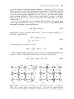
On the other hand, a pure screw dislocation can climb if the excess vacancies convert
it
into
a
helix, as in Fig.
11.10.
Here the turns of the helical dislocation possess
Figure
11.10:
Formation of a helical segment on an initially straight screw dislocation
lying along
[loo]
in a primitive-cubic crystal by progressive addition of vacancies to the
core.
For
graphic purposes, each vacancy is represented by a vacancy-type prismatic loop
of
atomic size.
(a)
Vacancy in a crystal with an initial straight screw dislocation nearby.
(b)
Configuration after a vacancy has joined the dislocation.
(c)-(
e)
Configurations after two,
three, and
four
vacancies have been added.
‘ODetails are discussed
by
Balluffi and Granato
[19].
11
4
DISLOCATION
CLIMB
269
strong edge components and, once formed, continue to climb as mixed dislocation
segments.
Additional factors may play a role during dislocation climb in many systems.
These include the possibility that jogs may be able to nucleate heterogeneously at
nodes or regions of sharp curvature. Also, in low stacking-fault-energy materials,
the dislocation may be dissociated into two partial dislocations bounding a ribbon
of stacking fault as shown in Fig.
9.10.
In such cases, the jogs may also be dissoci-
ated and possess a relatively high formation energy, causing the climb to be more
difficult
[2,
191.
11.4.2 Experimental Observations
Reviews of experimental observations of the efficiency with which dislocations climb
under different driving forces have been published
[18-221.
A wide range of semi-
quantitative results is available only for metals, including:
Vacancy quenching experiments where the destruction rate at climbing dis-
locations of supersaturated vacancies obtained by quenching the metal from
an elevated temperature is measured (see the analysis of this phenomenon in
the following section)
Dislocation loop annealing where the rate at which dislocation loops shrink
by means of climb is measured (see analysis in following section)
Sintering experiments where the rate at which vacancies leave voids and are
then destroyed at climbing dislocations is measured
Of main interest is the efficiency of climb and its dependence on the magnitude of
the force driving the climb process. In general, the efficiency of climbing dislocations
as sources increases as the driving force increases, since more energy is then available
to drive the climb. A convenient measure
of
the relative magnitude of this force is
the energy change,
gsl
which is achieved per crystal site created as a result of the
climb.
All dislocations, including dissociated dislocations in lower-stacking-fault-energy
metals and relatively nondissociated dislocations in high-stacking-fault-energy met-
als, operate as highly efficient sources when
lgsj
is large, as in rapidly quenched
metals
[20].
However, when
lgsl
is reduced, lower efficiencies, which may become
very small, are found for the lower-stacking-fault-energy metals. The efficiencies
for the higher-stacking-fault-energy metals appear to fall
off
less rapidly with
Jgs
1.
This may be understood on the basis of the tendency of the dislocations to contain
more jogs as
lgsl
increases and the greater difficulty in forming jogs on dissociated
dislocations than on undissociated dislocations because of the larger jog energies of
the former.
11.4.3
Climbing Dislocations
as
Sinks
for
Excess Quenched-in Vacancies.
Dislocations are
generally the most important vacancy sources that act to maintain the vacancy
concentration in thermal equilibrium as the temperature
of
a crystal changes. In
the following, we analyze the rate at which the usual dislocation network in a
Analyses
of
Two
Climb Problems
270
CHAPTER
11:
MOTION
OF
DISLOCATIONS
crystal destroys excess supersaturated vacancies produced by rapid quenching from
an elevated temperature during isothermal annealing at a lower temperature.
If
the dislocations in the network are present at a density Pd (dislocation line length
per unit volume), a reasonable approximation is that each dislocation segment acts
as the dominant vacancy sink in a cylindrical volume centered on it and of radius
R
=
(rpd)-ll2.
The problem is then reduced to the determination of the rate at
which excess vacancies in the cylinder diffuse to the dislocation line as illustrated
in Fig. 11.11. The diffusion system is assumed
to contain two components (A-type
atoms and vacancies) and is network constrained. Equation 3.68 for the diffusion
of vacancies is applicable in this case, and therefore
+
Jv
=
-DVVCV
(1
1.26)
According to the results in Section 11.4.2, the dislocations should act as highly ef-
fective sinks for the highly supersaturated vacancies. We therefore assume diffusion-
limited kinetics in which each dislocation segment is capable of maintaining the va-
cancies in local thermal equilibrium at its core, represented as a cylinder of effective
radius R,, where R, is of atomic dimensions. Also, in this type of problem, the effect
of the dislocation climb motion on the diffusion of the vacancies to the dislocation
can be neglected
to
a good approximation
[2,
231.
Using the separation-of-variables
method (Section 5.2.4), the diffusion equation corresponding to Eq. 3.69,
may be solved subject to the conditions
cv
=
c?
cv
=
cb
dCV
dr
for
r
=
R, and t
2
0
for
R,
<
r
5
R
and t
=
0
-0
forr=RandtLO
(11.27)
(11.28)
where
cb
is the quenched-in vacancy concentration and
c?
is the equilibrium va-
cancy concentration maintained at the “surface”
of
the dislocation core at the an-
Figure
11.11:
Vacancy diffusion fields
in
cylindrical cells
(of
radius
R)
around
dislocations acting
as
line sinks
(of
radius
Ro).
11.4:
DISLOCATION CLIMB
271
nealing temperature. The solution shows that the fraction of the excess vacancies
remaining in the system decays with time according to
(11.29)
where the
an
are the roots of
Yo(Roan)Jl(Ran)
-
Jo(Roan)Yl(Ran)
=
0
(11.30)
and
Jn
and
Yn
are Bessel functions of the first and second kind
of
order
n
[24].
For typical values of
Ro
and
R,
the first term in Eq. 11.29 will be dominant except
at very early times when the fraction decayed is small [24]. The major portion
of the excess vacancy decay will therefore be essentially exponential [i.e.,
f(t)
exp(-a:Dvt)]. Finally, it is noted that the above treatment does not take account
of the effect of the dislocation stress field on the diffusivity of the vacancies,
as
discussed in Section 3.5.2. In general, this stress field is of importance only within
a relatively small distance from the dislocation. Under these circumstances, its
effect during the major portion of the decay can be approximated in a simple
manner by making
a
relatively small change in the value of the effective dislocation
core radius,
R,
[25]. Since the roots of Eq. 11.30 are fairly insensitive to the value
of
Ro,
the decay rate is also rather insensitive to this choice of
R,.
The effect of
the stress field will therefore be relatively small.
Shrinkage
of
Dislocation
Loops
by Climb.
Prismatic dislocation loops are often
formed in crystals by the precipitation
of
excess vacancies produced by quench-
ing
or
by fast-particle irradiation (see Exercise 11.7). Once formed, these loops
tend to shrink and be eliminated by means
of
climb during subsequent thermal an-
nealing. A number of measurements of loop shrinkage rates have been made, and
analysis of this phenomenon
is
therefore of interest
[2].
In this section we calculate
the isothermal annealing rate
of
such
a
loop located near the center of a thin film
in a high-stacking-fault-energy material (such as Al) where the climb efficiency will
be high, and the shrinkage rate is therefore diffusion-limited.
The situation is illustrated in Fig. 11.12a. The loop is taken as an effective torus
of large radius,
RL,
with much smaller core radius,
Ro,
and the film thickness is
2d
with
d
>>
RL.
The vacancy concentration maintained in equilibrium with the loop
Figure
11.12:
(a)
Vacancy diffusion fluxes around a dislocation loop
(of
radius
RL)
shrinking by climb in a thin
film
of
thickness
2d.
(b)
Spherical approximation
of
a diffusion
field in (a).
272
CHAPTER
11:
MOTION
OF
DISLOCATIONS
at the surface of the torus, c?(loop), is larger than the equilibrium concentration,
c"vqco), maintained at the flat film surfaces. These concentrations can differ con-
siderably for small loops, and the approximation leading to Eq. 3.72, which ignored
variations in cv throughout the system, cannot be employed. Equation 3.69 can be
used to describe the vacancy diffusion. Vacancies therefore diffuse away from the
"surface" of the loop to the relatively distant film surfaces, and the loop shrinks as
it generates vacancies by means of climb.
The concentration, cT(loop), can be found by realizing that the formation energy
of a vacancy at the climbing loop is lower than at the flat surface because the loop
shrinks when a vacancy is formed, and this allows the force shrinking the loop (see
Section 11.2.3) to perform work. In general, N;q
=
exp[-Gf/(kT)] according
to
Eq. 3.65, and therefore
(11.31)
where
Gf(m)
-
Gf(1oop) is the work performed by the force on the shrinking loop
during the formation of a vacancy. The number of vacancies stored in the loop
is
NV
=
.irRib/R. The reduction in the radius of the loop due to formation of a
vacancy by climb is then 6RL/6Nv
=
-R/(2rbR~). Therefore,
R
2.irbR~
G;(CO)
-
Gv(loop)
f
=
-
2.ir~L1.12
(1
1.32)
- -
where the force has been evaluated with Eq. 11.8.
The vacancy diffusion field around the toroidal loop will be quite complex, but
at distances from it greater than about
~RL,
it
will appear approximately as shown
in Fig. 11.12a.
A
reasonably accurate solution to this complex diffusion problem
may be obtained by noting that the total flux to the two flat surfaces in Fig.
11.12~
will not differ greatly from the total flux that would diffuse to a spherical surface
of radius
d
centered on the loop as illustrated in Fig. 11.12b. Furthermore, when
d
>>
RL,
the diffusion field around such a source will quickly reach a quasi-steady
state [20, 261, and therefore
v2cv
=
0
(11.33)
(A
justification of this conclusion will be obtained from the analysis of the growth
of spherical precipitates carried out in Section 13.4.2.) In the steady state, the
vacancy current leaving the loop can be written as
where
C
is the electrostatic capacitance of a conducting body with the same toroidal
geometry as the loop placed at the center of a conducting sphere
so
that the ge-
ometry resembles Fig. 11.12b. This result is a consequence of the similarity of the
concentration fields, c(z,
y,
z),
and electrostatic-potential fields,
$(z,
y,
z),
which
are obtained by solving Laplace's equation in steady-state diffusion (V2c
=
0)
and
electrostatic potential
(V2$
=
0)
problems, respectively
[20,
261. The shrinking
11.4:
DISLOCATION
CLIMB
273
rate of the loop is then
RI
-
-
6RL
-
R
bNv
-
(11.35)
6t
2.irbR~
bt
2rbR~
-_
-
2r
*D
epbC2/[4x(l-v)kTR~]
ln(4R~/R,)
-
1
f
b
In( 8RL/Ro)
This final result is obtained by using Eqs. 8.17, 11.31,
11.32,
11.34, and the relation
C
=
nRL/ ln(8RL/Ro) for the capacitance of a torus in a large space when
RL
>>
R, [27].
Analyses of the climbing rates of many other dislocation configurations are of
interest, and Hirth and Lothe point out that these problems can often be solved by
using the method of superposition (Section 4.2.3)
[2].
In such cases the dislocation
line source or sink is replaced by a linear array
of
point sources for which the
diffusion solutions are known, and the final solution is then found by integrating
over the array. This method can be used to find the same solution of the loop-
annealing problem
as
obtained above.
As in Fig. 11.13, the loop can be represented by an array of point sources each
of
length R,. Using again the spherical-sink approximation of Fig.
11.12b
and re-
calling that
d
>>
RL
>>
R,, the quasi-steady-state solution of the diffusion equation
in spherical coordinates for a point source at the origin shows that the vacancy
diffusion field around each point source must be
of
the form
a1
c:(r
)
-
cv
(m)
=
-
r’
I
eq
(1
1.36)
where
a1
is
a
constant to be determined. The value of
a1
is found by requiring
that the concentration everywhere along the loop be equal to c?(loop). This con-
centration is due to the contributions of the diffusion fields of all the point sources
around the loop, and therefore, from Fig. 11.13 and using R,
<<
RL,
(1
1.37)
ceVq(1oop)
-
ceVq(m)
=
2a1
=-In 2al
(x)
~RL
Ro
Figure
11.13:
point sources.
Annealing prismatic dislocation loop taken as a circular array
of
vacancy
274
CHAPTER
11:
MOTION
OF
DISLOCATIONS
Note that the integral is terminated at the cutoff distance
R0/2
in order to avoid
a singularity. The vacancy concentration
at
a
distance from the loop appreciably
greater than
RL
can now be found by treating the loop itself as an effective point
source made up of all the point sources on its circumference. The number of these
sources is
~TRL~R,,
and therefore
The vacancy current leaving the loop is then
[c7(lOOp)
-
c~(co)]
(11.39)
d
~RL
dr
In(
~RL /Ro)
I
=
4rr2Dv- [cv(r)]
=
47rDv
in agreement with the results of the previous analysis.
rate of loops have been described
[19,
281.
Bibliography
Applications of Eq. 11.35 and closely related equations to the observed annealing
1.
2.
3.
4.
5.
6.
7.
8.
9.
10.
11.
12.
13.
14.
15.
S.M. Allen and E.L. Thomas.
The Structure
of
Materials.
John Wiley
&
Sons, New
York, 1999.
J.P. Hirth and
J.
Lothe.
Theory
of
Dislocations.
John Wiley
&
Sons, New York, 2nd
edition, 1982.
I.S. Sokolnikoff.
Mathematical Theory
of
Elasticity.
McGraw-Hill, New York, 1956.
J.
Weertman. High velocity dislocations. In P.G. Shewmon and
V.F.
Zackay, editors,
Response
of
Metals to High Velocity Deformation,
pages 205-247, New York, 1961.
Interscience.
F.R.N. Nabarro.
Theory
of
Crystal Dislocations.
Clarendon Press, Oxford, 1967.
C. Kittel.
Introduction to Solid State Physics.
John Wiley
&
Sons, New York, 3rd
edition, 1967.
F.R.N. Nabarro, editor.
Dislocations
in
Solids (Series),
volume 1-12. Elsevier North-
Holland, New York, 1979-2004.
J.
Friedel.
Dislocations.
Pergamon Press, Oxford, 1964.
U.F. Kocks, A.S. Argon, and M.F. Ashby. Thermodynamics and kinetics of slip.
Prog.
Muter. Sci.,
19:l-288, 1975.
W.G. Johnston and
J.J.
Gilman. Dislocation velocities, dislocation densitites, and
plastic flow in lithium fluoride crystals.
J.
Appl. Phys.,
30(2):129-144, 1959.
J.
Weertman. Dislocation mechanics at high strain rates. In R.W. Rohde,
B.M.
Butcher, J.R. Holland, and C.H. Kames, editors,
Metallurgical Eflects at High Strain
Rates,
pages 319-332, New York, 1973. Plenum Press.
C.S.
Smith. Metallographic studies of metals after explosive shock.
Trans. AIME,
J. Weertman. Plastic deformation behind strong shock waves.
Mech. Muter.,
5(1):13-
28, 1986.
B.L. Holian. Modeling shock-wave deformation via molecular-dynamics.
Phys. Rev.
AS. Nowick and B.S.
Berry.
Anelastic Relaxation
in
Crystalline Solids.
Academic
Press, New York, 1972.
212(
10):574-589, 1958.
A,
37(7):2562-2568, 1988.
EXERCISES
275
16.
J.
Lothe.
Theory of dislocation climb in metals.
J.
Appl. Phys.,
31(6):1077-1087,
1960.
17. R.M. Thomson and R.W. Balluffi.
Kinetic theory of dislocation climb
I.
General
18. R.W. Balluffi. Mechanisms of dislocation climb.
Phys. Status Solidi,
31(2):443-463,
19. R.W. Balluffi and A. V. Granato. Dislocations, vacancies and interstitials. In F.R.N.
Nabarro, editor,
Dislocations in Solids,
volume 4, pages 1-133, Amsterdam, 1979.
North-Holland.
20. A.P. Sutton and R.W. Balluffi.
Interfaces in Crystalline Materials.
Oxford University
models for edge and screw dislocations.
J.
Appl. Phys.,
33(3):803-817, 1962.
1969.
Press, Oxford, 1996.
21.
D.N.
Seidman and R.W. Balluffi. Dislocation as sources and sinks for point defects
in metals. In R.R. Hasiguti, editor,
Lattice Defects and Their Interactions,
pages
911-960, New York, 1967. Gordon and Breach.
22. R.W. Balluffi. Voids, dislocation loops and grain boundaries as sinks for point defects.
In M.
T.
Robinson and F.W. Young, editors,
Proceedings
of
the Conference on Funda-
mental Aspects
of
Radiation Damage in Metals,
volume 2, pages 852-874, Springfield,
VA, 1975. National Technical Information Service,
US.
Department of Commerce.
23. R.W. Balluffi and D.N. Seidman. Diffusion-limited climb rate of a dislocation: Effect
of climb motion on climb rate.
J.
Appl. Phys.,
36(7):2708-2711, 1965.
24. D.N. Seidman and R.W. Balluffi. Sources of thermally generated vacancies in single
25. F.S. Ham. Stress assisted precipitation on dislocations.
J.
Appl. Phys.,
30(6):915-926,
crystal and polycrystalline gold.
Phys. Rev.,
139(6A):1824-1840, 1965.
1959.
26. C.P. Flynn. Monodefect annealing kinetics.
Phys. Rev.,
133(2A):A587, 1964.
27. H. Buchholz.
Electrische und Magnetische Potentialfelder.
Springer-Verlag, Berlin,
28. D.N. Seidman and R.W. Balluffi. On the annealing of dislocation loops by climb.
Phil.
1957.
Mag.,
13:649-654, 1966.
29.
J.
Bardeen and C. Herring. Diffusion in alloys and the Kirkendall effect. In J.H. Hol-
lomon, editor,
Atom Movements,
pages 87-111. American Society
for
Metals, Cleve-
land, OH, 1951.
30. W.T. Read.
Dislocations in Crystals.
McGraw-Hill, New York, 1953.
EXERCISES
11.1
Show that
Eq.
11.4 for the osmotic force on an edge dislocation may be
generalized for
a
mixed dislocation in the form
(1
1.40)
where
-
-kT
R
B
=
b
-In
(s)
(11.41)
276
CHAPTER
11:
MOTION
OF
DISLOCATIONS
Solution.
The climb force is normal to the glide plane, which contains both the Burgers
vector and the tangent vector. The unit normal vector to the glide plane is therefore
so
(11.42)
Since the climb distance that results from the destruction of
6Nv
vacancies
is
now
)
~Nv,
using
Eqs.
3.64 and 3.66,
11.2
Interpret the line tension,
pb2,
of a dislocation to be a force that acts along its
length in a direction to decrease its length (see Eq.
11.9).
Using a simple geo-
metrical argument, show that the curvature force per unit length of dislocation
acting locally on a curved segment of dislocation is then just
/f;cl
=
pb2/R,
where
R
is the radius of curvature.
Solution.
The line-tension forces acting on
a
curved differential segment of dislocation
having a radius of curvature
R
due to its line tension will be as shown in Fig. 11.14.
The net force exerted on the segment toward the concave side is then
pb2
ds
df
=
2pb2
sin
(f)
M
pb2
dB
=
-
R
and therefore
ds
Figure
11.14:
Line tension forces on
a
curved dislocation segment.
(1
1.44)
(11.45)
11.3
Use Eq.
11.12
to show that a dislocation
in
a crystal possessing a uniform
nonequilibrium concentration of point defects and a uniform stress field will
EXERCISES
277
tend to adopt a helical form. Note that both a circle and a straight line are
special forms of a helix.
Solution.
The dislocation will tend to adopt a form for which the net force on it given
by Eq. 11.12 is everywhere zero.
We
therefore want to show that a helical dislocation
will possess a tangent vector
f
that satisfies
pb
2
-+[x(d-d)=O
dt
ds
(
11.46)
To
evaluate
t,
we recall that the equation for a helix with
its
axis along
z
is
F=
iacose +jasine
+
Lpe
(11.47)
where
6
is the polar angle in the zy-plane,
a
is
the radius of the circular projection on
the zy-plane, and
27rp
is the distance between successive turns along
z.
Therefore,
and
A
dr'
1
<=-=[-'
;a sine
+
ja cos
e
+
Lp]
Jm
ds
dt
d2r'
A
a
- -
=
-[icose+jsine]-
ds
ds2
a2 +p2
(11.48)
(11.49)
Comparing the last result with Eq.
11.10,
we see that the curvature given by
IC
=
./(a2
+p2)
is constant everywhere and that the principal normal vector at any point
0:
the hzlix is pointed toward the helix axis and
is
perpendicular to
it.
Also,
the vectors
B
and
d
are constant vectors independent of
(.
If
we now take the axis of the helix to
be along
(2-
d',
so
that
(d
-
d',
=
L
(B
-
4
and put the results above into Eq. 11.46,
we find that
it
is satisfied if
(11.50)
Note that the solution has the form of a circle when
p
=
0
and a straight line along the
axis when
p
+
m.
11.4
When
a
metal crystal free of applied stress and containing screw disloca-
tion segments is quenched
so
that supersaturated vacancies are produced, the
screw segments are converted into helices by climb. Show that the converted
helices can be at equilibrium with a certain concentration of supersaturated
vacancies and find an expression for this critical concentration in terms of
appropriate parameters of the system. Use the simple line-tension approxi-
mation leading to Eq.
11.12.
We note that the helix will grow by climb
if
the
vacancy concentration in the crystal exceeds this critical concentration and
will contract if it falls below it.
Sohtion.
In this case,
ci=
0,
and therefore we must have
(11.51)
The axis of the helix
is
parallel to
g,
which, in turn,
is
parallel to
g,
and therefore
Eq. 11.50 of Exercise 11.3 applies in the form
(11.52)