MODELLING OF MECHANICAL SYSTEM VOLUME 2 Episode 8 potx
Bạn đang xem bản rút gọn của tài liệu. Xem và tải ngay bản đầy đủ của tài liệu tại đây (434.66 KB, 40 trang )
258 Structural elements
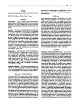
Figure 4.54. Collision of two beams, asymmetrical case
which start with equal and opposite velocities at t = 0. The contact time is equal
to the back and forth travelling time along an equivalent beam of length 2L.No
waves are excited and the velocities of the beams are simply interchanged by the
collision. The last case corresponds to an asymmetrical system. The upper plot of
Figure 4.54 shows a global view of the impact, which agrees satisfactorily with the
conditions [4.100] and the lower plot focuses on the collision itself. Contact time
depends on the beam properties and it may be noticed that waves are excited by
the impact, which are clearly visible in the trajectory of the second beam (dashed
line in Figure 4.54).
Chapter 5
Plates: in-plane motion
Plates are structural components used as walls, roofs, panels, windows, etc.
They are modelled as two-dimensional structures characterized by a plane geometry
bounded by a contour comprising straight and/or curved lines. Plates are intended to
resist various load conditions, broadly classified as in-plane and out-of-plane loads,
that is forces either parallel or perpendicular to the plane of the plate, respectively.
It is found convenient to study their response properties by separating first the
in-plane and the out-of-plane motions. In-plane motions of plates are generally
marked by the coupling between the two in-plane components of the displacement
field. Such a coupling gives rise to new interesting features of in-plane motions with
respect to the longitudinal motions of straight beams. Coupling between in-plane
and out-of-plane motions occurs in the presence of in-plane preloads and will be
considered in the next chapter. On the other hand, for mathematical convenience
in using Cartesian coordinates, presentation will focus first on rectangular plates.
Then use of curvilinear coordinates will be introduced to consider plates bounded
by curved contours.
260 Structural elements
5.1. Introduction
5.1.1 Plate geometry
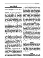
As shown in Figure 5.1, structural elements called plates are characterized by
the two following geometrical properties:
1. One dimension, termed the thickness, denoted h, is much smaller than the
other two (length L
1
and width L
2
for a rectangular shape, diameter D for a
circular one etc.). This allows one to model the mechanical properties of plates
by using a two-dimensional solid medium.
2. The geometrical support of the 2D model is the midsurface, taken at h/2ifthe
material is homogeneous. In contrast to the case of shells to be studied later, this
surface is flat and called the midplane of the plate. The border lines of the con-
tour of the midplane are called edges, which can be straight or/and curved lines.
A few other definitions concerning plate geometry are useful. As a
three-dimensional body, the plate is bounded by closed surfaces comprising the so
called faces and edge surfaces. If the plate thickness is uniform, the faces are flat
and parallel to the midplane, whereas the edge surfaces can be cylindrical or plane,
depending on the plate geometry. Intersection of two edge surfaces defines a corner
edge. Finally, it is also found convenient to orientate the contour by defining a posit-
ive unit vector normal to the midplane, which points from the lower face to the upper
face of the plate. The usual positive orientation is in the anticlockwise direction.
5.1.2 Incidence of plate geometry on the mechanical response
As a preliminary, it is useful to outline a few generic features of the response
properties of plates which serve as a guideline to organize the presentation of this
Figure 5.1. Plates: geometrical definitions
Plates: in-plane motion 261
and the next chapters. As will be verified ‘a posteriori’, they arise as a consequence
of the concept of midplane.
Considering first linear motions about an equilibrium position with zero or
negligible stress level, it can be stated that:
1. In-plane loads, i.e. parallel to the midplane, are balanced by in-plane stresses,
which can be normal (compressive or tensile forces) and/or tangential (in-plane
shear forces).
2. Out-of-plane loads, i.e. perpendicular to the midplane, are balanced by bending
and torsional moments and by transverse shear forces.
3. If the load is oblique, all the previous stresses participate with the equi-
librium. However, in the absence of initial stresses, coupling between the
in-plane and the out-of-plane motions of the plate can be discarded. So
the response to an oblique load is obtained by superposing the responses on the
in-plane and to the out-of-plane components of the load, which can be studied
separately.
Considering then linear motions about a prestressed equilibrium position, it can
be stated that:
1. In-plane initial stresses contribute to the out-of-plane equilibrium of a plate
through restoring, or alternatively, destabilizing forces, similar to those arising
in straight beams when prestressed axially.
2. As a limit case, the forces that contribute to the out-of-plane equilibrium of
suitably stretched skin structures originate almost completely from the in-plane
stresses which are prescribed initially. Such skin structures are referred to as
membranes. A membrane can be seen as an idealized two-dimensional medium
which has no flexural rigidity, in contrast with plates and shells.
3. Like cables, or strings, membranes belong to the general class of the so
called tension structures which can support mechanical loads by tensile
stresses only.
In agreement with these preliminary remarks, it is found appropriate to invest-
igate first the motions of plates which involve in-plane components of force and
displacement fields only. Such in-plane fields are termed membrane components,or
fields, as their nature is basically the same as those induced when a skin is stretched
in its own plane. On the other hand, it is also found convenient to study first the
case of rectangular plates as they can be described using Cartesian coordinates.
Non rectangular plates have to be analysed by using oblique or curved coordin-
ates, depending on the specificities of their shapes, which are more difficult to
manipulate mathematically.
262 Structural elements
5.2. Kirchhoff–Love model
5.2.1 Love simplifications
Let us consider a rectangular plate of uniform thickness h. The coordinates of
a material point are expressed in a direct Cartesian frame Oxyz, where Oxy is the
midplane of the plate, the origin O is at a corner, the axes Ox and Oy are parallel
to the edges of lengths L
x
and L
y
respectively. The unit vectors of the Ox, Oy, Oz
axes are denoted
i,
j,
k respectively. A main cross-section is obtained by cutting
mentally the plate with a plane which is perpendicular to the midplane and parallel
either to Ox or to Oy. An ordinary cross-section is neither parallel to Ox nor to Oy,
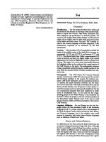
P(x, y, 0) or P(x, y) designating a point of the midplane; the intersection of two
cross-sections passing through P defines a normal fibre (see Figure 5.2). As h is
very small with respect to L
x
and to L
y
, the following simplifying assumptions
can be made, which hold in the case of small deformations:
1. The normal fibres behave as a rigid body.
2. As the midplane is deformed, the normal fibres remain perpendicular to it.
3. The normal stresses acting on the planes parallel to the midplane are consistent
with the first hypothesis of rigidity of the normal fibres.
These assumptions can be understood as a natural extension to the two-
dimensional case of the basic beam model. In particular, the second hypothesis
means that there is no shear between two neighbouring normal fibres as the plate
bends, in agreement with the Bernoulli–Euler model.
5.2.2 Degrees of freedom and global displacements
According to the first assumption made above, the motion of a normal fibre can
be described by using five independent parameters, termed global displacements,
Figure 5.2. Cross-sections and normal fibre in a plate
Plates: in-plane motion 263
Figure 5.3. Global displacements: translation and rotation variables
which are referred to a current point P(x, y) of the midplane. They are shown in
Figure 5.3 and defined as follows:
1. the longitudinal displacement in the direction Ox: X(x, y; t)
i
2. the lateral displacement in the direction Oy: Y(x, y; t)
j
3. the transverse displacement in the direction Oz: Z(x, y; t)
k
4. the rotation around the Ox axis: ψ
x
(x, y; t)
i
5. the rotation around the Oy axis: ψ
y
(x, y; t)
j
After deformation, the point P(x, y,0) is transformed into P(x +X, y +Y , Z).
5.2.3 Membrane displacements, strains and stresses
5.2.3.1 Global and local displacements
The components X, Y are termed membrane displacements, which are sufficient
to describe the in-plane motions of the plate. In such motions, all the material points
lying on a same normal fibre have the same displacements. So, global and local
displacements are also the same, see Figure 5.4.
ξ(x, y; t) =
X = X(x, y; t)
i + Y(x, y; t)
j [5.1]
5.2.3.2 Global and local strains
In agreement with [5.1], the local and the global strains are also the same:
ε = η.
Restricting the study to the case of small deformations, by substituting [5.1] into
264 Structural elements
Figure 5.4. Local and global displacements for in-plane motion
Figure 5.5. Membrane strains
the small strain tensor [1.25], we get:
η
xx
=
∂X
∂x
; η
yy
=
∂Y
∂y
; η
xy
= η
yx
=
1
2
∂X
∂y
+
∂Y
∂x
[5.2]
The geometrical meaning of these quantities is illustrated in Figure 5.5. They
comprise two normal and one shear component. η
xx
is the relative longitudinal
elongation (Ox direction), η
yy
is the relative lateral elongation (Oy direction) and
η
xy
= η
yx
= γ/2 is the in-plane shear strain which is also expressed in terms of
the shear angle γ . Finally, the strain tensor [5.2] can be conveniently written in the
following matrix form:
[ε]=[η]=
∂X
∂x
1
2
∂Y
∂x
+
∂X
∂y
1
2
∂X
∂y
+
∂Y
∂x
∂Y
∂y
[5.3]
Plates: in-plane motion 265
Figure 5.6. Global stress components
5.2.3.3 Membrane stresses
The membrane strains induce the membrane local stresses σ
xx
, σ
yy
, σ
xy
which
are independent of z. These quantities are integrated over the plate thickness to
produce the global membrane stresses which are suitably defined as forces per unit
length:
N
xx
N
yy
N
xy
=
h/2
−h/2
σ
xx
σ
yy
σ
xy
dz = h
σ
xx
σ
yy
σ
xy
[5.4]
In [5.4] the stress components are used to form a stress vector instead of a
stress tensor. To avoid confusion when using the matrix notation, the local and
global stress vectors are denoted [σ ] and [
N ] respectively, whereas the local
and global stress tensors are denoted [σ ] and [N ].
As shown in Figure 5.6, they are consistent with the sign convention adopted
for the three-dimensional stresses (see Figure 1.6). N
xx
and N
yy
are the normal
stresses, directed along the normal vectors of the edge surfaces parallel to Oy and
Ox respectively, and N
xy
= N
yx
are the in-plane shear stresses directed in the
tangential directions Oy and Ox respectively. The global stress tensor is written in
matrix notation as:
[N ]=
N
xx
N
yx
N
xy
N
yy
[5.5]
5.3. Membrane equilibrium of rectangular plates
5.3.1 Equilibrium in terms of generalized stresses
Because the geometry of rectangular plates is very simple, there is no difficulty
in deriving the equilibrium equations using the Newtonian approach i.e. direct
balancing of the forces acting on an infinitesimal rectangular element, as shown in
the next subsection. However, it is also of interest to solve the problem by using
Hamilton’s principle, which deals with scalar instead of vector quantities. It is
266 Structural elements
applied first to the case of rectangular plates in subsection 5.3.1.2, and then to the
case of orthogonal curvilinear coordinates in section 5.4.
5.3.1.1 Local balance of forces
Let us consider a rectangular plate loaded by the external force field:
f
(e)
(x, y; t) = f
(e)
x
i + f
(e)
y
j [5.6]
where
f
(e)
is a force density per unit area of the midplane surface.
In Figure 5.7, the balances of the longitudinal and lateral forces acting on an
elementary rectangle dx, dy are sketched, which extend to the two-dimensional case
the longitudinal force balance of straight beams shown in Figure 2.9. Of course,
in the 2D case, it is appropriate to distinguish between a longitudinal and a lateral
force balance, giving rise thus to two distinct equilibrium equations. Furthermore,
the contribution of the tangential stresses due to the in-plane shear must be added
to the in-plane normal stresses. As shear stresses are symmetric N
xy
= N
yx
, the
moments are automatically balanced, not requiring any additional condition to
describe the equilibrium of the rectangle.
The two equilibrium equations, in the Ox, Oy directions respectively, are
written as:
ρh
¨
X −
∂N
xx
∂x
+
∂N
yx
∂y
= f
(e)
x
ρh
¨
Y −
∂N
yy
∂y
+
∂N
xy
∂x
= f
(e)
y
[5.7]
Figure 5.7. In-plane forces acting on an infinitesimal element of the rectangular plate
Plates: in-plane motion 267
In tensor notation, the system [5.7] is expressed as:
ρh
¨
X ·
ℓ −
div
N
·
ℓ =
f
(e)
·
ℓ [5.8]
where
ℓ denotes a unit vector in the plane of the plate.
It may be noticed that equation [5.8] is similar to the general 3D equation [1.32]
and is independent of the coordinate system (intrinsic form), in contrast with [5.7]
which holds in the case of Cartesian coordinates only.
5.3.1.2 Hamilton’s principle
Here, in addition to the surface force density defined in [5.7], an edge force
density is also introduced:
t
(e)
(x, y; t) =
t
(e)
x
i + t
(e)
y
j
[5.9]
The Lagrangian is written as:
L =
L
x
0
L
y
0
{e
κ
− e
s
+ w
F
}dx dy +
(C)
w
T
ds [5.10]
where e
κ
is the kinetic and e
s
the strain energy densities per unit area; w
F
is the
work density of an external force field acting within the plate midplane and w
T
is
the work density of an external force field acting on the contour (C) of the plate
and s is the curvilinear abscissa along (C).
Hamilton’s principle is first written as:
δ[A]=
t
2
t
1
L
x
0
L
y
0
{δ[e
κ
]−δ[e
s
]+δ[w
F
]}dx dy +
C
δ[w
T
]ds
dt = 0
[5.11]
The remaining task is to evaluate the terms of [5.11] in a suitable way, as detailed
just below.
The kinetic energy density is found to be:
e
κ
=
1
2
ρh(
˙
X
2
+
˙
Y
2
) [5.12]
268 Structural elements
Its variation is integrated with respect to time, giving:
t
2
t
1
L
x
0
L
y
0
{δ[e
κ
]}dx dy
dt =−
t
2
t
1
L
x
0
L
y
0
ρh{
¨
XδX +
¨
YδY}dx dy
dt
[5.13]
As long as the material law is not specified, it is not possible to express the
strain energy density analytically. Nevertheless, its virtual variation is still given
by (cf. the 3D equation [1.47]):
δ[e
s
]=
N : δη ⇐⇒ δ[e
s
]=N
ij
δη
ij
[5.14]
So, in Cartesian coordinates,
δ[e
s
]=N
xx
∂δX
∂x
+ N
xy
∂δY
∂x
+ N
yx
∂δX
∂y
+ N
yy
∂δY
∂y
[5.15]
Therefore, we arrive at:
−
t
2
t
1
L
x
0
L
y
0
{δ[e
s
]}dx dy
dt
=+
t
2
t
1
L
x
0
L
y
0
∂N
xx
∂x
+
∂N
yx
∂y
δX +
∂N
xy
∂x
+
∂N
yy
∂y
δY
dx dy
dt
−
t
2
t
1
dt
L
y
0
[N
xx
δX +N
xy
δY]
L
x
0
dy −
t
2
t
1
dt
L
x
0
[N
yx
δX +N
yy
δY]
L
y
0
dx
[5.16]
Turning finally to the virtual work of external loading, for the surface forces we
get immediately:
t
2
t
1
L
x
0
L
y
0
{δ[w
F
]}dx dy
dt =
t
2
t
1
L
x
0
L
y
0
{f
(e)
x
δX + f
(e)
y
δY}dx dy
dt
[5.17]
and for the edge forces,
t
2
t
1
(C)
{δ[w
T
]}ds
dt =
t
2
t
1
(C)
{t
(e)
x
δX + t
(e)
y
δY}ds
dt [5.18]
By cancelling the δX and δY cofactors in the surface and contour integrals
arising in [5.13] and [5.16] to [5.18], the equations [5.7] and the following boundary
Plates: in-plane motion 269
conditions are readily derived. The contour integral [5.18] is developed as:
(C)
{t
(e)
x
δX + t
(e)
y
δY}ds
=
L
x
0
t
(e)
x
δX + t
(e)
y
δY
y=0
dx +
L
y
0
t
(e)
x
δX + t
(e)
y
δY
x=L
x
dy
+
L
x
0
t
(e)
x
δX + t
(e)
y
δY
y=L
y
dx +
L
y
0
t
(e)
x
δX + t
(e)
y
δY
x=0
dy
[5.19]
Equation [5.19] used with the contour integrals of [5.16] gives:
L
x
0
t
(e)
x
+ N
yx
δX +
t
(e)
y
+ N
yy
δY
y=0
dx = 0
⇒ t
(e)
x
+ N
yx
y=0
= 0; t
(e)
y
+ N
yy
y=0
= 0
L
x
0
t
(e)
x
− N
yx
δX +
t
(e)
y
− N
yy
δY
y=L
y
dx = 0
⇒ t
(e)
x
− N
yx
y=L
y
= 0; t
(e)
y
− N
yy
y=L
y
= 0
L
y
0
t
(e)
x
+ N
xx
δX +
t
(e)
y
+ N
xy
δY
x=0
dy = 0
⇒ t
(e)
x
+ N
xx
x=0
= 0; t
(e)
y
+ N
xy
x=0
= 0
L
y
0
(t
(e)
x
− N
xx
)δX + (t
(e)
y
− N
xy
)δY
x=L
x
dy = 0
⇒ t
(e)
x
− N
xx
x=L
x
= 0; t
(e)
y
− N
xy
x=L
x
= 0
[5.20]
It may be checked that the signs of the different stress terms which appear
in the boundary conditions [5.20] are consistent with the general definition of
stresses given in Chapter 1, subsection 1.2.3. This is illustrated in Figure 5.8 in
which positive edge forces are applied to the four edges of the plate. For instance,
according to [5.20] N
xx
is found to be equal to the external edge force t
(e)
x
at x = L
x
and to −t
(e)
x
at x = 0. A slightly different way to check the signs consists of claiming
that a positive external force t
(e)
x
applied along x = L
x
must induce tensile, hence
positive, stresses and the same force when applied along x = 0 must induce
compressive, hence negative stresses. Of course, the signs of the stresses will also
agree with those found in a 3D rectangular parallelepiped and in a straight beam.
270 Structural elements
Figure 5.8. Stresses induced by a uniform edge loading
5.3.1.3 Homogeneous boundary conditions
If
t
(e)
≡ 0, the following standard homogeneous boundary conditions arise:
1. Fixed edge:
X and Y = 0 [5.21]
2. Sliding edge:
parallel to O x : Y = 0; N
yx
= 0
parallel to O y : X = 0; N
xy
= 0
[5.22]
3. Free edge:
parallel to O x : N
yy
= 0; N
yx
= 0
parallel to O y : N
xx
= 0; N
xy
= 0
[5.23]
5.3.1.4 Concentrated loads
As in the case of beams, it is found convenient to describe concentrated loads by
using singular distributions. For example a force per unit length distributed along
the line x = x
0
is written as:
f
(e)
=
f
(e)
x
(y; t)
i + f
(e)
y
(y; t)
j
δ(x −x
0
) [5.24]
Then the equilibrium equations are written in terms of distributions as:
ρh
¨
X −
∂N
xx
∂x
+
∂N
yx
∂y
= f
(e)
x
(y; t)δ(x −x
0
)
ρh
¨
Y −
∂N
xy
∂x
+
∂N
yy
∂y
= f
(e)
y
(y; t)δ(x −x
0
)
[5.25]
Plates: in-plane motion 271
The integration in the domain [x
0
−ε, x
0
+ε] where ε is arbitrarily small gives
the equations:
ρh
¨
X −
∂N
xx
∂x
+
∂N
yx
∂y
= 0; ρh
¨
Y −
∂N
yy
∂y
+
∂N
xy
∂x
= 0
N
xx
|
x0−
− N
xx
|
x0+
= f
(e)
x
(y, t); N
xy
|
x0−
− N
xy
|
x0+
= f
(e)
y
(y, t)
[5.26]
In the same way, a force concentrated at the point x
0
, y
0
is defined by the
distribution:
f
(e)
=
f
(e)
x
(t)
i + f
(e)
y
(t)
j
δ(x −x
0
) ∩ δ(y − y
0
) [5.27]
In [5.27] the symbol ∩means that the application point of the loading is located
at the intersection of the lines x = x
0
and y = y
0
. Accordingly, the equilibrium
equations are written in terms of distributions as:
ρh
¨
X −
∂N
xx
∂x
+
∂N
yx
∂y
= f
(e)
x
(t)δ(x −x
0
) ∩ δ(y − y
0
)
ρh
¨
Y −
∂N
xy
∂x
+
∂N
yy
∂y
= f
(e)
y
(t)δ(x −x
0
) ∩ δ(y − y
0
)
[5.28]
By integrating [5.28] over the intervals [x
0
− ε, x
0
+ ε; y
0
− η, y
0
+ η] where
ε and η are arbitrarily small, the equations of motion can be written as:
ρh
¨
X −
∂N
xx
∂x
+
∂N
yx
∂y
= 0; ρh
¨
Y −
∂N
xy
∂x
+
∂N
yy
∂y
= 0
N
xx
(x
0−
, y
0
) − N
xx
(x
0+
, y
0
) + N
yx
(x
0
, y
0−
) − N
yx
(x
0
, y
0+
) = f
(e)
x
(t)
N
yy
(x
0
, y
0−
) − N
yy
(x
0
, y
0+
) + N
xy
(x
0−
, y
0
) − N
xy
(x
0+
, y
0
) = f
(e)
y
(t)
[5.29]
The stress discontinuities are easily understood by turning back to Figure 5.8
and letting the plate dimensions tend to zero. For example, the balance of forces
along the edge Ox is:
N
xx
(x
0
+ ε, y) − N
xx
(x
0
− ε, y) + N
yx
(x, y
0
+ η)
− N
yx
(x, y
0
− η) + f
(e)
x
(t) = 0 [5.30]
where the inertia forces are neglected, since they vanish when ε and η tend to
zero. So, the limit of [5.30] identifies with the second equation [5.29]. In the same
272 Structural elements
manner, calculation performed on a plate of infinitesimal width 2ε would result in
equation [5.26].
5.3.2 Elastic stresses
The three-dimensional law of elasticity as given by equations [1.36] to [1.38]
is particularized here to the case of plane stresses. In agreement with the
Kirchhoff–Love assumptions, the out-of-plane components of the strain tensor
and of the elastic stress tensor are set to zero. Substituting such simplifications into
[1.38], the following strain-stress relationships are derived:
ε
xx
=
1 + ν
E
σ
xx
−
ν
E
(σ
xx
+ σ
yy
) =
1
E
σ
xx
−
ν
E
σ
yy
ε
yy
=
1 + ν
E
σ
yy
−
ν
E
(σ
xx
+ σ
yy
) =
1
E
σ
yy
−
ν
E
σ
xx
ε
xy
=
1 + ν
E
σ
xy
[5.31]
The stress–strain relationships can be conveniently written in matrix form as:
ε
xx
ε
yy
2ε
xy
=
1
E
1 −ν 0
−ν 10
002(1 + ν)
σ
xx
σ
yy
σ
xy
⇐⇒
σ
xx
σ
yy
σ
xy
=
E
1 − ν
2
1 ν 0
ν 10
00
1 − ν
2
ε
xx
ε
yy
2ε
xy
[5.32]
where the local strain and stress components are used to form a strain and a stress
vector denoted [ε] and [σ ] respectively.
In terms of global quantities the relation [5.32] reads as:
η
xx
η
yy
2η
xy
=
1
Eh
1 −ν 0
−ν 10
002(1 + ν)
N
xx
N
yy
N
xy
⇐⇒
N
xx
N
yy
N
xy
=
Eh
1 − ν
2
1 ν 0
ν 10
00
1 − ν
2
η
xx
η
yy
2η
xy
[5.33]
where the global strain and stress components are used to form a strain vector and
a stress vector denoted [η] and [
N ] respectively.
Plates: in-plane motion 273
note. – way of writing the stress–strain relationships
Because of the symmetry of the strain and stress tensors it follows that 2σ
xy
ε
xy
=
σ
xy
ε
xy
+ σ
yx
ε
yx
. Hence, in [5.32] the notation 2ε
xy
= γ in place of ε
xy
allows
one to write the elastic energy density as the scalar product of a stress and a strain
vectors:
2e
e
=
σ : ε =[σ ]
T
[ε];
where [ε]
T
=
ε
xx
ε
yy
2ε
xy
[σ ]
T
=
σ
xx
σ
yy
σ
xy
note. – 3D elasticity versus plane stress and strain approximations
According to the 3D elasticity law, there is an incompatibility between a plane
stress model and a plane strain model, because if σ
zz
is assumed to vanish, then
ε
zz
=−ν(σ
xx
+σ
yy
)/E differs from zero as a result of the Poisson effect. Never-
theless, in the Kirchhoff–Love model the strains in the direction of plate thickness
are discarded and at the same time a plane stress model is assumed to hold. Again,
such a simplification is of the same nature as that made in beams by assuming that
the cross-sections are rigid.
5.3.3 Equations and boundary conditions in terms of displacements
Substituting the strain–displacement relationships [5.3] into the stress–strain
relationships [5.33], we obtain the global membrane stresses:
N
xx
=
Eh
1 − ν
2
∂X
∂x
+ ν
∂Y
∂y
; N
yy
=
Eh
1 − ν
2
∂Y
∂y
+ ν
∂X
∂x
N
xy
=
Eh
2(1 + ν)
∂X
∂y
+
∂Y
∂x
= Gh
∂X
∂y
+
∂Y
∂x
[5.34]
Substituting the stresses [5.34] into the equilibrium equations [5.7], we obtain
the vibration equations:
ρh
¨
X −
Eh
1 − ν
2
∂
∂x
∂X
∂x
+ ν
∂Y
∂y
− Gh
∂
∂y
∂X
∂y
+
∂Y
∂x
= f
(e)
x
(x, y; t)
ρh
¨
Y −
Eh
1 − ν
2
∂
∂y
∂Y
∂y
+ ν
∂X
∂x
− Gh
∂
∂x
∂Y
∂x
+
∂X
∂y
= f
(e)
y
(x, y; t)
[5.35]
On the left-hand side of [5.35] it is appropriate to make the distinction between
at least two stiffness operators. The first one, proportional to E, describes the
274 Structural elements
stretching forces, and the second one, proportional to G, describes the in-plane
shear forces. Furthermore, both the stretching and the shear operators are found to
couple the longitudinal and the lateral motions together, since a displacement in
the Ox direction is found to induce a displacement in the Oy direction and vice
versa. The coupling terms appearing in the stretching operator is clearly due to
the Poisson effect. The coupling terms appearing in the shear operator are inherent
in 2D shear effect. They can be put in evidence even more clearly by writing the
equations [5.35] in matrix form:
ρh 0
0 ρh
¨
X
¨
Y
+
−
Eh
1 − ν
2
∂
2
∂x
2
− Gh
∂
2
∂y
2
−
Ehν
1 − ν
2
+ Gh
∂
2
∂x∂y
−
Ehν
1 − ν
2
+ Gh
∂
2
∂x∂y
−
Eh
1 − ν
2
∂
2
∂y
2
− Gh
∂
2
∂x
2
×
X
Y
=
f
(e)
x
f
(e)
y
[5.36]
In [5.36] we recognize the canonical form [M][¨q]+[K][q]=[Q
(e)
] of the
linear equations of any forced conservative mechanical system. In contrast with
discrete systems, the stiffness coefficients are partial derivative linear operators.
The mass matrix is diagonal and the non diagonal terms of the stiffness matrix are
symmetric and made up of even operators, so as to comply with the condition of
self-adjointness of [M] and [K].
The homogeneous boundary conditions describing edge elastic supports can be
inferred from the inhomogeneous conditions [5.20], by assimilating first the support
forces to an “external” load applied to the edges:
t
(e)
x
(0, y) =−K
xx
X(0, y); t
(e)
x
(L
x
, y) =−K
xx
X(L
x
, y)
t
(e)
y
(0, y) =−K
xy
Y(0, y); t
(e)
y
(L
x
, y) =−K
xy
Y(L
x
, y)
t
(e)
y
(x,0) =−K
yy
Y(x,0); t
(e)
y
(x, L
y
) =−K
yy
Y(x, L
y
)
t
(e)
x
(x,0) =−K
yx
Y(x,0); t
(e)
x
(x, L
y
) =−K
yx
Y(x, L
y
)
The supports are described by the stiffness coefficients K
xx
, K
yy
, K
xy
, K
yx
defined as forces per unit area (Nm
−2
or Pa using the S.I. units). If the edge equi-
librium conditions are considered as force balances between the ‘external’ loads
Plates: in-plane motion 275
and the internal stresses, then they are written as:
Eh
1 − ν
2
∂X
∂x
+ ν
∂Y
∂y
− K
xx
X
x=0
=0;
Eh
1 − ν
2
∂X
∂x
+ ν
∂Y
∂y
+ K
xx
X
x=L
x
=0
Gh
∂X
∂y
+
∂Y
∂x
− K
xy
Y
x=0
=0;
Gh
∂X
∂y
+
∂Y
∂x
+ K
xy
Y
x=L
x
=0
Eh
1 − ν
2
∂Y
∂y
+ ν
∂X
∂x
− K
yy
Y
y=0
=0;
Eh
1 − ν
2
∂Y
∂y
+ ν
∂X
∂x
+ K
yy
Y
y=L
y
=0
Gh
∂X
∂y
+
∂Y
∂x
− K
yx
X
y=0
=0;
Gh
∂X
∂y
+
∂Y
∂x
+ K
yx
X
y=L
y
=0
[5.37]
Of course, the standard boundary conditions [5.21] to [5.23] may be recovered
as limit cases of [5.37] where the appropriate stiffness coefficients tend either to
zero or to infinity.
5.3.4 Examples of application in elastostatics
5.3.4.1 Sliding plate subject to a uniform longitudinal load at the free edge
The rectangular plate (h, L
x
, L
y
) shown in Figure 5.9, is loaded along the edge
x = L
x
by a uniform longitudinal force density t
(e)
x
i. The edge x = 0 slides freely
Figure 5.9. Plate subject to a uniform longitudinal force density at one edge
276 Structural elements
in the lateral direction Oy. The other edges are free. In terms of distributions the
equilibrium equations are:
−
Eh
1 − ν
2
∂
2
X
∂x
2
+ ν
∂
2
Y
∂x∂y
− Gh
∂
2
X
∂y
2
+
∂
2
Y
∂x∂y
= t
(e)
x
δ(L
x
− x)
−
Eh
1 − ν
2
∂
2
Y
∂y
2
+ ν
∂
2
X
∂x∂y
− Gh
∂
2
Y
∂x
2
+
∂
2
X
∂x∂y
= 0
The boundary conditions are:
1. Sliding edge x = 0:
X(0, y) = 0; N
xy
= 0 ⇐⇒
∂X(0, y)
∂y
+
∂Y(0, y)
∂x
= 0
2. Free edge x= L
x
:
N
xx
= 0 ⇐⇒
∂X(L
x
, y)
∂x
+ ν
∂Y(L
x
, y)
∂y
= 0
N
xy
= 0 ⇐⇒
∂X(L
x
, y)
∂y
+
∂Y(L
x
, y)
∂x
= 0
3. Free edges y =±L
y
/2:
N
yy
= 0 ⇐⇒
∂Y(x, ±L
y
/2)
∂y
+ ν
∂X(x, ±L
y
/2)
∂x
= 0
N
xy
= 0 ⇐⇒
∂X(x, ±L
y
/2)
∂y
+
∂Y(x, ±L
y
/2)
∂x
= 0
As a first step to solving the problem, the longitudinal equilibrium equation,
written in terms of distributions, is replaced by the homogeneous equation:
−
Eh
1 − ν
2
∂
2
X
∂x
2
+ ν
∂
2
Y
∂x∂y
− Gh
∂
2
X
∂y
2
+
∂
2
Y
∂x∂y
= 0
and the related homogeneous boundary condition is replaced by the non homogen-
eous condition:
N
xx
|
L
x
−
= t
(e)
x
⇐⇒
Eh
1 − ν
2
∂X(L
x
, y)
∂x
+ ν
∂Y(L
x
, y)
∂y
= t
(e)
x
As is rather obvious, any polynomial which is linear in x and y satisfies
the homogeneous partial derivative equations. So the general solution may be
written as:
X = a
1
x + b
1
y + c
1
; Y = a
2
x + b
2
y + c
2
Plates: in-plane motion 277
where the coefficients a
1
, b
1
, etc. are determined by the boundary conditions, as
detailed below.
1. Sliding edge x = 0
X(0, y) = 0 ⇒ c
1
= 0, b
1
= 0;
∂X(0, y)
∂y
+
∂Y(0, y)
∂x
= 0 ⇒ b
1
+ a
2
= 0
It is worth pointing out that the second condition implies that N
xy
≡ 0 is zero
everywhere in the plate, including at the edges.
2. Loaded edge x = L
x
a
1
+ νb
2
=
t
(e)
x
(1 − ν
2
)
Eh
3. Free edges y =±L
y
/2
N
yy
= 0 ⇒ b
2
+ νa
1
= 0
Hence, N
yy
as well as N
xy
, N
yx
are found to vanish everywhere in the plate,
including at the edges; so the stress field is uniaxial and uniform N
xx
= t
(e)
x
. The
displacement field is found to be:
X =
t
(e)
x
Eh
x; Y =
−νt
(e)
x
Eh
y + c
2
where c
2
is arbitrary since the plate can move freely along the Oy axis. The problem
can be further particularized by prescribing c
2
= 0, which means that the solution
is symmetric about the Ox axis:
X =
t
(e)
x
Eh
x; Y =
−νt
(e)
x
Eh
y [5.38]
The only difference between the plate solution [5.38] and the corresponding beam
solution lies in the lateral contraction proportional to Poisson’s ratio, which is
related to the longitudinal stretching. Finite element solution of the problem is
shown in colour plate 4, the load being applied to the x = L
x
and to the x = L
x
/2
line successively. In the last case, only the part of the plate 0 ≤ x ≤ L
x
/2is
deformed. The finite jump of N
xx
across the loaded line is smoothed out by the
finite element discretization process.
5.3.4.2 Fixed instead of sliding condition at the supported edge
The condition along the edge x = 0 becomes X(0, y) = 0; Y(0, y) = 0. A priori,
it could be surmised that the plate response does not differ much from the former
278 Structural elements
one, though solution must be quite different from the mathematical standpoint since
the relation N
xy
≡ 0 does not hold anymore. Actually, the problem has no analytical
solution in closed form. Numerical solution obtained by using the finite element
method is shown in colour plates 5. It can be verified that by fixing the supported
edge, the lateral contraction is prevented and shear stresses arise. Nevertheless,
such effects are concentrated in the vicinity of the supported edge, in agreement
with the Saint-Venant principle (cf. Chapter 1, subsection 1.5.1).
5.3.4.3 Three sliding edges: plate in uniaxial strain configuration
Here, the lateral contraction related to the longitudinal stretching of the plate
is prevented by prescribing the sliding conditions X = 0atx = 0 and Y = 0
at y =±L
y
/2. Accordingly, it seems natural to anticipate a solution of the type
X = a
1
x; Y ≡ 0 which, after some elementary algebra, is found to be:
X =
t
(e)
x
Eh
(1 − ν
2
)x; Y ≡ 0
N
xx
= t
(e)
x
; N
yy
= νN
xx
; N
xy
= 0; η
xx
=
t
(e)
x
Eh
; η
yy
= η
xy
= 0
[5.39]
5.3.4.4 Uniform plate stretching
As sketched in Figure5.10, the plateis stretched in the longitudinal andthe lateral
directions by a tensile load distributed uniformly on the four edges. The plate centre
is supposed fixed, so central symmetry holds. Again, the displacements X and Y
are linear functions and because of the boundary conditions, there is no shear. Thus,
we get:
N
xy
= 0 ⇒ b
1
+ a
2
= 0
Figure 5.10. Rectangular plate stretched in the Ox and Oy directions
Plates: in-plane motion 279
The normal stresses verify:
N
xx
=
Eh
1 − ν
2
(a
1
+ νb
2
) = t
x
= t
(e)
N
yy
=
Eh
1 − ν
2
(b
2
+ νa
1
) = t
y
= t
(e)
⇒ a
1
= b
2
b
2
=
t
(e)
(1 − ν)
Eh
and because of the central symmetry:
X(x, y) =
t
(e)
(1 − ν)
Eh
x
Y(x, y) =
t
(e)
(1 − ν)
Eh
y
[5.40]
5.3.4.5 In-plane uniform shear loading
Again, the centre of the rectangular plate is fixed. It is loaded by shear forces
uniformly distributed on the four edges, as shown in Figure 5.11. Of course, the
resultant of the loading vanishes. The moment of the longitudinal forces is M
z1
=
(t
(e)
L
x
)L
y
, where L
y
/2 is the lever arm. Similarly, the moment of lateral forces
is M
z2
=−(t
(e)
L
y
)L
x
where the lever arm is L
x
/2. Thus, the resultant moment
is also null and the global condition for plate equilibrium is fulfilled. Because of
the central symmetry and the absence of normal stresses, the solution in terms of
displacements is necessarily of the type:
X = by Y = ax [5.41]
The shear stress field follows as:
N
xy
= N
yx
= Gh(a +b) = γGh = t
(e)
h [5.42]
Figure 5.11. Plate uniformly loaded by shear forces
280 Structural elements
However, a and b are not single valued because the plate can rotate freely around
the Oz axis, normal to the plate.
5.3.4.6 In-plane shear and bending
A rectangular plate is supported along the edge x = 0 and loaded by a uni-
form shear force along the edge x = L, the resultant of which is denoted F , see
Figure 5.12. A priori, it would be desirable to prescribe a fixed support condition
at x = 0, in order to compare the plate response to the in-plane shear load and
the bending response to F of the same plate, modelled as a cantilevered beam.
Such a comparative study is expected to provide us with enlightening information
concerning both the relative importance of shear and normal stresses in the plate
and the hypothesis of cross-sectional rigidity in beam models, as a function of L/ℓ.
Unfortunately, solving analytically the problem stated just above is far from being
a simple task, as difficulties arise in complying with the fixed boundary conditions.
It is thus found more convenient to approximate the boundary conditions, based on
physical reasoning.
At first, the plate solution is expected to be not very far from the beam solution
(Bernoulli–Euler model) which, for the present problem, is written as:
Y
b
(x) =
FL
3
6EI
3
x
L
2
−
x
L
3
As Y
b
is independent of y, the stress field related to the bending solution is of
the type:
σ
xx
= α(L −x)y, σ
yy
= 0, σ
xy
= 0
Figure 5.12. Lateral shear loading
Plates: in-plane motion 281
In the plate model shear differs from zero; so a plate stress field not far from the
beam model could be anticipated as:
N
xx
= α(x −L)y; N
yy
= 0; N
xy
= β
ℓ
2
2
− y
2
The normal stresses are identical to those obtained from the beam theory and
the form postulated for the shear stress N
xy
agrees with the boundary condition
N
xy
= 0 at thelateral edges y =±ℓ/2. Furthermore, to be compatiblewith the edge
loading, the shear stress field along the edge x = L needs to be an even function
of y. As a first approximation it is legitimate to adopt a parabolic distribution,
leading to the resultant:
F =
ℓ/2
−ℓ/2
t
(e)
y
(L, y) dy =
ℓ/2
−ℓ/2
βh
ℓ
2
2
− y
2
dy
It follows that β = 6F /(hℓ
3
) = F/(2I)
The moment associated with F is:
M(x) = (x − L)F = α(x −L)h
ℓ/2
−ℓ/2
y
2
dy,soα =
12F
hℓ
3
=
F
I
Using the stress–strain and the strain–displacement relationships, the following
system of partial derivative equations is obtained:
∂X
∂x
=
1
E
N
xx
− νN
yy
⇒
∂X
∂x
=
F
EI
(x − L)y;
∂Y
∂y
=
1
E
N
yy
− νN
xx
⇒
∂Y
∂y
=−ν
F
EI
(x − L)y
∂X
∂y
+
∂Y
∂x
=
1
G
N
xy
⇒
∂X
∂y
+
∂Y
∂x
=
F
2GI
ℓ
2
2
− y
2
By integrating the two first equations, it follows that:
X(x, y) =
Fxy(x − 2L)
2EI
+ X
0
(y); Y(x, y) =−
νF(x − L)y
2
2EI
+ Y
0
(x)
Substitution of these results into the shear equation leads to:
Fℓ
2
8GI
=
dX
0
dy
+
Fy
2
2GI
−
νFy
2
2EI
+
dY
0
dx
+
Fx(x −2L)
2EI
282 Structural elements
so,
dX
0
dy
= a −
(2 + ν)Fy
2
2EI
;
dY
0
dx
= b −
Fx(x −2L)
2EI
where a +b =
Fℓ
2
8GI
The resulting displacement field is:
X
0
(y) = ay + c −
F(2 +ν)
6EI
y
3
; Y
0
(x) = bx +d +
F
6EI
(3Lx
2
− x
3
)
X(x, y) =
Fxy(x − 2L)
2EI
−
F(2 +ν)
6EI
y
3
+ ay + c
Y(x, y) =−
νF(x − L)y
2
2EI
+
F
6EI
(3Lx
2
− x
3
) + bx + d
However, if such a solution is adopted, it is impossible to fix the edge x = 0in
its integrity, so the boundary condition is modified by fixing the point O only. This
new condition is clearly less rigid that the former one. It leads to:
X(0, 0) = Y(0, 0) = 0 ⇒ c = d = 0
Supplementary conditions are still needed to determine the coefficients a and b.
They can be selected in such a way as to rigidify the support. A suitable condition
which prevents shear strain at the fixed point is:
∂X
∂y
0,0
−
∂Y
∂x
0,0
= 0 ⇒ a −b = 0 ⇒ a = b =
Fℓ
2
16GI
Therefore, the final solution is written as:
X(x, y) =
Fx(x −2L)y
2EI
−
F(2 +ν)
6EI
y
3
+
Fℓ
2
16GI
y
Y(x, y) =+
F
6EI
(3Lx
2
− x
3
) −
νF(x − L)y
2
2EI
+
Fℓ
2
16GI
x
[5.43]
The displacement field [5.43] must be understood as an approximate solution to
the “real” problem which comply with the fixed edge condition. However, accord-
ing to Saint-Venant’s principle, it may be expected that it provides satisfactory
results, except in the vicinity of the fixed edge. This important point can be checked
by comparison with the beam results, as outlined below.
1. In [5.43], the first term of the lateral displacement is precisely the beam solution
Y
b
(x).