REAL-TIME SYSTEMS DESIGN AND ANALYSIS phần 5 doc
Bạn đang xem bản rút gọn của tài liệu. Xem và tải ngay bản đầy đủ của tài liệu tại đây (540.51 KB, 53 trang )
188 4 SOFTWARE REQUIREMENTS ENGINEERING
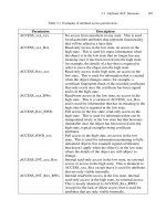
Table 4.6 Imperatives found in requirements specifications and their purpose [Wilson97]
Imperative Purpose
Shall Dictates provision of fundamental capability
Must Establishes performance requirements or constraints
Must not Establishes performance requirements or constraints
Is required to Used in specifications statements written in passive voice
Are applicable Used to include, by reference, standards or other documentation as
an addition to the requirements being specified
Responsible for Used as an imperative for systems whose architectures are already
defined
Will Generally used to cite things that the operational or development
environment are to provide to the capability being specified
Should Not recommended for use
ž
Weak phrases
ž
Imperatives
Imperatives are given in Table 4.6.
Continuances follow an imperative and introduce the specification of require-
ments at a lower level. Continuances include:
ž
“Below”
ž
“As follows”
ž
“Following”
ž
“Listed”
ž
“In particular”
ž
“Support”
Directives are words and phrases that point to illustrative information:
ž
“Figure”
ž
“Table”
ž
“For example”
Options give the developer latitude in satisfying the specifications, and include:
ž
“Can”
ž
“May”
ž
“Optionally”
Weak phrases, which should be avoided in SRS, include:
ž
“Adequate”
ž
“As a minimum”
4.9 REQUIREMENTS VALIDATION AND REVIEW 189
ž
“As applicable”
ž
“Be able to”
ž
“Be capable”
ž
“But not limited to”
ž
“Capability of”
ž
“Capability to”
ž
“Effective”
ž
“If practical”
ž
“Normal”
ž
“Provide for”
ž
“Timely”
ž
“TBD”
These fine-grained measures can, minimally, be used to measure certain size
qualities of the SRS, such as:
ž
Lines of text
ž
Imperatives
ž
Subjects (unique words following imperatives)
ž
Paragraphs
Certain ratios can also be computed from these fine-grained measures, which
can be used to judge the fitness of the specification of these ratios are shown in
Table 4.7
Readability statistics, similar to those used to measure writing level, can be
used as a quality measure for SRS. Readability statistics include:
ž
Flesch Reading Ease Index Number of syllables/word and words/sentence.
ž
Flesch-Kincaid Grade Level Index Flesch score converted to a grade level
(standard writing is about seventh or eighth grade).
Table 4.7 Certain ratios derived from software requirements specifications and their
purpose
Ratio Purpose
Imperatives to subjects Indicates level of detail
Lines of text to imperatives Indicates conciseness
Number of imperatives found at each
document levels
Counts the number of lower-level items that
are introduced at a higher level by an
imperative followed by a continuance
Specification depth to total lines of
text
Indicates conciseness of the SRS
190 4 SOFTWARE REQUIREMENTS ENGINEERING
ž
Coleman-Liau Grade Level Index Uses word length in characters and sen-
tence length in words to determine grade level.
ž
Bormuth Grade Level Index Same as Coleman-Liau.
Any of these requirements metrics can be incorporated into a metrics-management
discipline, and if used consistently and intelligently, will improve the real-time
system in the long run.
4.10 APPENDIX: CASE STUDY IN SOFTWARE REQUIREMENTS
SPECIFICATION FOR FOUR-WAY TRAFFIC INTERSECTION TRAFFIC
LIGHT CONTROLLER SYSTEM
The following is an excerpt from the SRS for the traffic intersection control
system introduced in Chapter 1. It embodies many of the elements discussed in
this chapter in more detail and provides a fully developed example of an object-
oriented approach to requirements specification of a complex real-time system.
1 INTRODUCTION
Traffic controllers currently in use comprise simple timers that follow a fixed
cycle to allow vehicle/pedestrian passage for a pre-determined amount of time
regardless of demand, actuated traffic controllers that allow passage by means
of vehicle/pedestrian detection, and adaptive traffic controllers that determine traf-
fic conditions in real-time by means of vehicle/pedestrian detection and respond
accordingly in order to maintain the highest reasonable level of efficiency under
varying conditions. The traffic controller described in this specification is capable of
operating in all three of these modes.
1.1 Purpose
This specification defines the software design requirements for an intersection
control system for simple, four-way pedestrian/vehicular traffic intersections. The
specification is intended for use by end users as well as software developers.
1.2 Scope
This software package is part of a control system for pedestrian/vehicular traffic
intersections that allows for (1) a fixed cycle mode, (2) an actuated mode, (3) a
fully adaptive automatic mode, (4) a locally controlled manual mode, (5) a remotely
controlled manual mode and (6) an emergency preempt mode. In the fully adaptive
automatic mode, a volume detection feature has been included so that the system
is aware of changes in traffic patterns. Pushbutton fixtures are also included so the
system can account for and respond to pedestrian traffic. The cycle is controlled by an
adaptive algorithm that uses data from many inputs to achieve maximum throughput
and acceptable wait-times for both pedestrians and motorists. A preempting feature
allows emergency vehicles to pass through the intersection in a safe and timely
manner by altering the state of the signals and the cycle time.
4.10 APPENDIX: CASE STUDY IN SOFTWARE REQUIREMENTS SPECIFICATION 191
1.3 Definitions, Acronyms, Abbreviations
The following is a list of terms and their definitions as used in this document.
1.3.1 10-Base T
Physical connection formed by a twisted-pair as described in IEEE 802.3. Networking
connection designed to transfer up to 10 megabits per second.
1.3.2 ADA
Americans With Disabilities Act.
1.3.3 API
Application Program Interface.
1.3.4 Approach
Any one of the routes allowing access to an intersection.
1.3.5 Arterial Road
A major traffic route or route used to gain access to a highway.
1.3.6 Aspect
The physical appearance of an illuminated traffic standard.
1.3.7 Attribute
Property of a class.
1.3.8 Cycle Time
The time required to complete an entire rotation (cycle) of traffic signals at any one
intersection.
1.3.9 Direct Route
A route directly through the intersection that does not require the vehicle to turn.
1.3.10 DOT
Department of Transportation.
1.3.11 Downstream
The normal travel direction for vehicles.
1.3.12 Ethernet
The most commonly used local area networking method as described in IEEE 802.3.
1.3.13 Intersection
A system, including hardware and software, that regulates vehicle and pedestrian
traffic where two or more major roads traverse. The class of intersection considered
in this specification has only two roads.
1.3.14 Manual Override
A device located at and physically connected to each intersection control system
that allows traffic regulatory personnel to control the intersection manually.
192 4 SOFTWARE REQUIREMENTS ENGINEERING
1.3.15 Method
Procedure within a class exhibiting an aspect of class behavior.
1.3.16 Message
An event thrown from one code unit and caught by another.
1.3.17 Occupancy Loop
A device used to detect the presence of vehicles in an approach or to count the
passage of vehicles using an approach.
1.3.18 Offset
The time difference between cycle start times at adjacent intersections. Applies only
to coordinated intersection control, which is not covered by this specification.
1.3.19 Orthogonal Route
A route through an intersection that requires a vehicle to turn.
1.3.20 Pedestrian Presence Detector
A button console located on the corner of an intersection which gives pedestrians
who wish to cross a street the ability to alert the intersection control system to
their presence.
1.3.21 Pedestrian Traffic Standard
Signals facing in the direction of pedestrian cross walks which have lighted indicators
marked ‘‘Walk’’ and ‘‘Don’t Walk.’’
1.3.22 Phase
The state of an intersection. A p articular period of the regulatory traffic pattern.
1.3.23 Remote Override
A computer host that includes a software interface allowing a remote administrator
to control the intersection remotely.
1.3.24 RTOS
Real-Time Operating System.
1.3.25 Secondary Road
A route that does not typically support high traffic volume or experiences less usage
relative to another route.
1.3.26 SNMP (Simple Network Management Protocol)
The de facto standard for inter-network management, defined by RFC 1157.
1.3.27 Split
The duty cycle for a given phase, expressed as a decimal or percentage.
1.3.28 Vehicle Traffic Standard
A traditional traffic signal with red, yellow, and green indicators.
4.10 APPENDIX: CASE STUDY IN SOFTWARE REQUIREMENTS SPECIFICATION 193
1.3.29 Upstream
Direction opposite to the normal direction of vehicle travel.
1.3.30 Vehicle Presence Detector
See Occupancy Loop.
1.3.31 WAN
Wide Area Network.
1.4 References
1. 10 base-T Ethernet (IEEE 802.3)
2. SNMP (RFC 1157)
3. ‘‘DEVELOPMENT OF AN ACTUATED TRAFFIC CONTROLPROCESS UTILIZ-
ING REAL-TIME ESTIMATED VOLUME FEEDBACK’’, September 2000
1.5 Overview
2 OVERALL DESCRIPTION
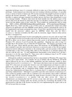
2.1 Intersection Overview
The intersection class to be controlled is illustrated in Figure 1.
SPEED
LIMIT
30
SPEED
LIMIT
55
OCCUPANCY
LOOP
N
E
S
W
PREVIOUS INTERSECTION (UPSTREAM)
NEXT INTERSECTION (DOWNSTREAM)
NEXT INTERSECTION (DOWNSTREAM)
ORTHOGONAL ROUTE
IDLE AVENUE (SECONDARY)
REAL TIME ROAD (ARTERIAL)
DIRECT ROUTE
All approaches are level,
tangent surfaces.
APPROACHES:
W-E
E-W
N-S
S-N
Figure 1 Intersection topography.
194 4 SOFTWARE REQUIREMENTS ENGINEERING
The target class of intersection has the following characteristics:
1. Four-way crossing.
2. Roadway gradients and curvatures are small enough to be neglected.
3. No right-turn or left-turn lanes or right-turn and left-turn signals (note, however,
that the intersection is wide enough to allow vehicles passing directly through
to pass to the right of vehicles turning left).
4. Intersecting roads of different priorities (e.g., one road may be an arterial while
the other may be a secondary road) or of equal priority.
5. Two vehicle traffic standards per approach: one suspended by overhead cable,
the other mounted on a pedestal.
6. One pedestrian crosswalk per approach.
7. Pedestrian traffic standards, pedestal mounted, on each side of each crosswalk.
8. Pedestrian presence detectors (pushbuttons) on each side of each crosswalk.
9. Stop-line vehicle presence detectors (loop detectors) in all approaches (one
per approach) for detecting vehicle presence and for counting vehicles passing
through the intersection.
2.2 Product Perspective
2.2.1 System Interfaces
These are described in detail in the sections below.
2.2.2 User Interfaces
2.2.2.1 Pedestrians
Pedestrian pushes button, generating service request to software and receives, in
time, the ‘‘Walk’’ signal.
2.2.2.2 Motor Vehicles
In ACTUATED mode, vehicle enters the intersection, generating service request to
software and receives, in time, the ‘‘Okay to Proceed’’ signal.
In ADAPTIVE mode, vehicle passes over the loop detector, increasing the vehicle
count, which, in turn, causes an adjustment in intersection timings.
2.2.2.3 Emergency Vehicle
Emergency vehicle operator activates the ‘‘emergency vehicle override signal’’,
generating priority service request to software and receives, in a preemptive time,
the ‘‘Okay to proceed’’ signal.
2.2.2.4 Traffic Regulatory Personnel
Traffic regulatory personnel will remove the manual override device from the control
box and press buttons to control the intersection manually.
2.2.2.5 Remote Operator
Remote operator uses a software control panel either to control the state of the
intersection directly or to observe and manipulate the parameters and state of a
specific intersection control system.
2.2.2.6 Maintainer
Maintainer accesses system through Ethernet port to perform maintenance.
4.10 APPENDIX: CASE STUDY IN SOFTWARE REQUIREMENTS SPECIFICATION 195
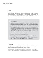
2.2.3 Hardware Interfaces
The Intersection Control System hardware interfaces are summarized in Figure 2 on
the following page.
2.2.3.1 Major Hardware Components – Summary
Table 1 Major intersection control system hardware components
Item Description Quantity
1 Intersection Controller Enclosure 1
1.1 Input Circuit Breaker 1
1.2 Input Transformer 1
1.3 Input Power Supply with UPS 1
1.4 Intersection Controller 1
1.5 Lamp Driver 20
1.6 Lamp Current Sensor 40
1.7 Green Signal Safety Relay 1
1.8 Manual Override Console 1
1.9 Vehicle Presence Detector Interface Unit (not shown in Figure 2) 4
1.10 Pedestrian Request Detector Interface Unit (not shown in Figure 2) 8
1.11 RJ-45 Ethernet Connector – DOT Network 1
1.12 RJ-45 Ethernet Connector – Maintenance 1
1.13 Enclosure Wiring A/R
2 Vehicle Traffic Standard – Suspended 4
3 Vehicle Traffic Standard – Pole Mounted 4
4 Pedestrian Traffic Standard 8
5 Pedestrian Request Detector 8
6 Vehicle Presence Detector 4
7 Emergency Vehicle Transponder 1
10 Field Wiring A/R
DON'T
WALK
WALK
DON'T
WALK
WALK
DOT NETWORK
I/O FOR LOOP,
PUSHBUTTONS
AND OTHER
APPROACHES
EMERGENCY VEHICLE
TRANSPONDER
GREEN/WALK
SIGNAL NEUTRAL
GREEN/WALK SIGNAL
NEUTRAL
GREEN/
WALK
SIGNAL
NEUTRAL
GREEN/WALK SIGNAL
NEUTRAL
GREEN/WALK SIGNAL
NEUTRAL
N
ETHERNET CONNECTION
MANUAL OVERRIDE
CONSOLE
REGULATED
OUTPUT
POWER
POWER SUPPLY
with UPS
MAINTENANCE PORT
LAMP
POWER
120 VAC
60 HZ
LAMP
DRIVER
(TYPICAL)
CURRENT FEEDBACK
CURRENT FEEDBACK
CURRENT FEEDBACK
CURRENT FEEDBACK
CURRENT FEEDBACK
SAFETY RELAY CONTROL
SAFETY RELAY
× 2
(Typical)
RED
YELLOW
GREEN
DON'T WALK
WALK
ON
FLASH
CONTROLLER
LOOP
PUSHBUTTONS
APPROACH W-E
APPROACH N-S
APPROACH S-N
NEUTRAL
APPROACH E-W (TYPICAL)
2
6
4
2
2
16
16
16
Figure 2 Intersection controller hardware (not all details and interconnects shown).
196
4.10 APPENDIX: CASE STUDY IN SOFTWARE REQUIREMENTS SPECIFICATION 197
2.2.3.2 Wired Interfaces – Internal
Hard-wired connections between the intersection controller and the following hard-
ware components within the intersection controller enclosure are provided:
1. Traffic Standard Lamp Drivers (20)
2. Traffic Standard Lamp Current Sensors (40)
3. Vehicle Presence Detector Interface Units (4)
4. Pedestrian Presence Detector Interface Units (4)
5. Green Signal Safety Relay (1)
6. Manual Override Console (1)
7. Maintenance Connector (2; 10-base T twisted pair)
2.2.3.3 Wired Interfaces – External
Hard-wired connections between the intersection control enclosure and the following
external hardware components are provided:
1. Pedestrian Presence Detector
2. Pedestrian Traffic Standard
3. Vehicle Presence Detector
4. Vehicle Traffic Standard
5. Emergency Vehicle Transponder
6. DOT Wide-Area Network (WAN)
2.2.3.4 Emergency Vehicle Transponder
The emergency vehicle transponder is a radio frequency link between the intersection
control system and the emergency vehicle override controller.
2.2.3.5 Ethernet Connection to DOT WAN
Interaction between the software system and the remote operator console is con-
ducted over a standard 10 base-T local area network. Each intersection control
system is identified with a unique, statically assigned IP address.
2.2.4 Software Interfaces
2.2.4.1 Operating System
The intersection controller interfaces to the RTOS via standard OS API calls.
2.2.4.2 Resource Managers
Interfaces to hardware are handled by resource managers not specified in this
SRS. Resource managers are assumed to have direct access to the object model
defined here.
2.2.4.3 Software Control Panel
The intersection control system must be able to interact with the software control
panel to allow remote user access. This interface provides a r emote user the ability
to modify system parameters, perform maintenance functions, or assume manual
control of the intersection. The standard protocol for this communication will be
SNMP version 1.
198 4 SOFTWARE REQUIREMENTS ENGINEERING
2.2.5 Communications Interfaces
The system will utilize TCP/IP’s SNMP interface for inter-system communication.
2.2.6 Memory Constraints
2.2.6.1 Flash Memory
Flash memory will be the memory media of choice for the system. The software
will require no more than 32 MB of flash memory for RTOS, application program,
and data.
2.2.6.2 RAM
RAM will be used for application execution. The system shall not require more than
32 MB of RAM. Upon boot, the RTOS, application program and static data needed
for execution will be copied from flash into the RAM.
2.2.7 Operations
1. Automatic, unattended operation (normal operation)
2. Local manual operation (through override console)
3. Remote manual operation (through WAN port)
4. Local observed operation (through maintenance port)
5. Remote observed operation (through WAN port)
6. Remote coordinated operation (option; through WAN port)
2.2.8 Site Adaptation Requirements
This is summarized in Section 2.1, above.
2.3 Product Functions
The Intersection Control System provides the following functions:
1. Control of the intersection vehicle traffic standards.
2. Control of the intersection pedestrian traffic standards.
3. Collection and processing of traffic history from all approaches.
4. Adaptive control of intersection timings in response to traffic flow.
5. Actuated control of intersection in response to vehicle presence.
6. Timed control of intersection in response to a fixed scheme.
7. Handling of pedestrian crossing requests.
8. Handling of emergency vehicle pre-emption.
9. Intersection control in response to manual override commands.
10. Intersection control in response to remote override commands.
11. Management of traffic history and incident log databases.
12. Handling of maintenance access requests from the maintenance port.
13. Handling of maintenance access requests from the DOT WAN.
2.4 User Characteristics
2.4.1 Pedestrians
General population, including persons with disabilities.
4.10 APPENDIX: CASE STUDY IN SOFTWARE REQUIREMENTS SPECIFICATION 199
2.4.2 Motor Vehicle
Automobiles and trucks, depending on roadway use limitations.
2.4.3 Traffic Regulatory Personnel
Authorized DOT, police, or other personnel trained in use of the Manual Override
console. Must have key to the system enclosure.
2.4.4 System Administrators
Authorized DOT personnel with training in the use of this system.
2.5 Constraints
System Constraints include the following:
1. Regulatory policy (e.g., ADA).
2. DOT specifications.
3. Local ordinances.
4. Hardware limitations.
5. Minimum time for pedestrian to cross.
6. Minimum stopping distance for vehicles.
7. Momentary power droops/outages.
8. Interfaces to other applications.
9. Audit functions.
10. Higher-order language requirements (OO language supported by RTOS
required).
11. Network protocols (e.g., SNMP).
12. Reliability requirements.
13. Criticality of the application.
14. Security considerations.
15. Safety considerations.
2.6 Assumptions and Dependencies
1. SI units are used for all physical quantities.
2. Commercially available RTOS is used.
3. Hardware interfaces have resource managers (drivers) already developed and
available for integration with the software system specified here.
4. DOT WAN will use SNMP to communicate with intersection control system.
5. Watchdog circuitry forces safe default intersection state through hardware.
3 SPECIFIC REQUIREMENTS
This section describes the basic functional elements of the intersection control
system. In particular, the software object model is described in detail, with attributes
and methods enumerated. External interfaces to users, hardware, and other software
elements are described, and background on the adaptive algorithm to be used
is provided.
200 4 SOFTWARE REQUIREMENTS ENGINEERING
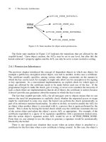
3.1 External Interface Requirements
3.1.1 User Interfaces
Normal Vehicular
Traffic Under
Signal Control
Pedestrian
Preempted
Crossing
Emergency
Vehicle
Preempted Traffic
Maintenance
Access
Remote
Parameter
Update
Remote Override
Manual Override
Intersection Controller
Motor Vehicle
Pedestrian
Emergency
Vehicle
Traffic
Control
Officer
DOT
Network
Maintainer
Figure 3 Top-level use-case diagram.
1. Vehicle Presence Detector – User: Motor Vehicle
2. Pedestrian Presence Detector – User: Pedestrian
3. Emergency Vehicle Override – User: Emergency Vehicle
4. Manual Override – User: Traffic Control Officer
5. Remote Override – User: DOT Officer
6. Maintenance Interface – User: Maintainer
3.1.2 Hardware Interfaces
1. Vehicle
2. Pedestrian crossing pushbutton
3. Traffic standard
4. Walk signal
4.10 APPENDIX: CASE STUDY IN SOFTWARE REQUIREMENTS SPECIFICATION 201
5. Hardware watchdog
6. Uninterruptible power supply
3.1.3 Software Interfaces
1. RTOS API calls.
2. Hardware resource manager interfaces.
3.1.4 Communications Interfaces
1. Interface to RTOS TCP/IP stack.
3.2 Classes/Objects
Figure 4 depicts the classes constituting the intersection control system software
application.
manualOverride
vehiclePresenceDetector
vehicleTrafficStandard
pedestrianTrafficStandard
trafficHistory incidentLog
approach
pedestrianRequestPushbutton
remoteOverride
intersectionController
networkInterface
transponderInterface
1
1
11
11 1
1
11
11
11
1
1
1
1
1
2
2
4
Figure 4 Preliminary intersection controller class diagram.
202 4 SOFTWARE REQUIREMENTS ENGINEERING
3.2.1 Intersection Controller
The Intersection Controller is responsible for managing the following functions:
1. Initialization.
2. Instantiation of contained objects.
3. Control of the intersection vehicle traffic standards.
4. Control of the intersection pedestrian traffic standards.
5. Collection and processing of traffic history from all approaches.
6. Adaptive control of intersection timings in response to traffic flow.
7. Actuated control of intersection in response to vehicle presence.
8. Timed control of intersection in response to a fixed scheme.
9. Handling of pedestrian crossing requests.
10. Handling of emergency vehicle pre-emption.
11. Intersection control in response to manual override commands.
12. Intersection control in response to remote override commands.
13. Management of traffic history and incident log databases.
14. Handling of maintenance access requests from the maintenance port.
15. Handling of maintenance access requests from the DOT WAN (wide area
network).
Table 2 below illustrates the attributes, methods, and events of the Interface
Controller class and Figure 5 illustrates the controller functional sequencing.
Table 2 Intersection controller class
Intersection Controller
Name Description
Attributes Approaches Array of Approach objects.
Manual Override Represents the Manual Override console.
Remote Override Represents the Remote Software console.
Traffic History Contains the traffic history for up to at least seven
(7) days.
Incident Log Contains the incident log for up to at least seven
(7) days.
Network Interface Object that provides an interface from the Network
resource manager (driver) to the Intersection
Controller object.
Emergency Vehicle
Interface
Object that provides an interface between the
Emergency Vehicle transponder and the
Intersection Controller object.
Mode Current operating mode of the Intersection
Controller.
4.10 APPENDIX: CASE STUDY IN SOFTWARE REQUIREMENTS SPECIFICATION 203
Table 2 (continued)
Intersection Controller
Name Description
Priority Relative priority of the approaches.
Cycle Time Time to complete a full traversal of all intersection
phases.
Splits Array of numbers defining the fraction of the cycle
time allocated to each phase.
Current Phase Current intersection phase.
Phase Time Remaining Time remaining until the intersection moves to the
next phase in the sequence.
Commanded Green
Signal Safety Relay
State
Based on the Current Phase, this attribute holds the
value required for the Green Signal Safety Relay
resource manager, which is responsible for driving
the relay.
Detected Green Signal
Safety Relay State
This holds the actual state of the Green Signal
Safety Relay.
Methods Initialize
Advance Phase Advance the intersection phase to the next phase in
the sequence.
Calculate Cycle
Parameters
Calculates the cycle time and splits for the next
cycle based on traffic data.
Events Phase Time Remaining
Value Reaches 0
Fires when the Phase Time Remaining timer
reaches 0.
Override Activated Fires when either the Manual Override or Remote
override is activated.
Override Canceled Fires when Overrides are deactivated.
Watchdog Timeout Fires on a watchdog trip.
Error Fires when an error occurs. Takes the Error code is a
parameter.
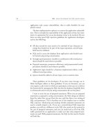
The corresponding traffic standard aspects are shown in Figure 6 below.
phase_6 phase_5
init
default_2
phase_4
phase_8 phase_7
phase_1
default_1
phase_3
default_3
phase_2
C
onTimerExpired
onTimerExpired
[priority = 3]
onDefaultSuccess
[priority = 2]
onTimerExpired
onTimerExpired
onInitSuccess
[priority = 1]
onTimerExpired
onTimerExpired
onTimerExpired
onDefaultSuccess
onTimerExpired
onDefaultSuccess
Figure 5 Statechart for intersection controller phase sequence.
204
4.10 APPENDIX: CASE STUDY IN SOFTWARE REQUIREMENTS SPECIFICATION 205
Flashing
DONT′T
WALK
Fashing
Yellow
Flashing
Red
Phase
Phase_1
Phase_2
Phase_3
Phase_4
Phase_5
Phase_6
Phase_7
Phase_8
Default_1
Default_2
Default_3
E-W/W-E
N-S/S-N
DONT
WALK
DONT
WALK
DONT
WALK
DONT
WALK
DONT
WALK
DONT
WALK
DONT
WALK
DONT
WALK
DONT
WALK
DONT
WALK
WALK
DONT
WALK
DONT
WALK
DONT
WALK
DONT
WALK
DONT
WALK
DONT
WALK
DONT
WALK
DONT
WALK
DONT
WALK
DONT
WALK
DONT
WALK
WALK
Figure 6 Traffic standard aspects for each phase.
206 4 SOFTWARE REQUIREMENTS ENGINEERING
3.2.2 Approach
This is the programmatic representation of an intersection approach.
The Approach object is responsible for managing the following functions:
1. Instantiation of contained objects.
2. Control of the traffic standards associated with the approach.
3. Handling of pedestrian crossing events.
4. Handling of loop detector entry and exit events.
5. Tracking the vehicle count.
Table 3 below illustrates the attributes, methods, and events of the Approach class.
Table 3 Approach class
Approach
Name Description
Attributes Pedestrian Traffic Standard Object representing the two pedestrian traffic
standards associated with the approach.
Vehicle Traffic Standards Object representing the two vehicle traffic
standards associated with the approach.
Pedestrian Service Button Object representing the two pedestrian service
pushbuttons associated with the approach.
Vehicle Presence Detector Object representing the proximity detection
loop, located at the stop line, associated
with the approach.
Vehicle Count Count of vehicles passing through the
approach.
Indication Array used to store the indications actually
being displayed on all associated traffic
standards.
Current Aspect Current commanded aspect corresponding to
the Intersection Controller phase.
Speed Limit Value (in km/h) of the speed limit associated
with the approach.
Methods Set Aspect Set the displayed aspect to the Commanded
Aspect.
Get Aspect Get the actual displayed aspect based on
signals from the current sensor hardware
resource manager.
Increment Count Increase the vehicle count by 1.
Reset Count Reset the vehicle count to 0.
4.10 APPENDIX: CASE STUDY IN SOFTWARE REQUIREMENTS SPECIFICATION 207
Table 3 (continued)
Approach
Name Description
Events Pedestrian Request Fires when a pedestrian request has been
made.
Vehicle Entry Fires when the loop detector detects vehicle
entry.
Vehicle Exit Fires when the loop detector detects vehicle
exit.
3.2.3 Pedestrian Traffic Standard
This is the programmatic representation of a pedestrian crossing signal.
The Pedestrian Traffic Standard object is responsible for managing the following
functions:
1. Displaying the commanded indication aspect from the Approach.
2. Determining the indication actually displayed.
Table 4 below illustrates the attributes, methods, and events of the Pedestrian
Service Button class.
Table 4 Pedestrian traffic standard class
Pedestrian Traffic Standard
Name Description
Attributes Commanded Aspect Commanded aspect from the Intersection
Controller.
Methods Set Indication Set the displayed indication to the
Commanded Indication.
Get Indication Get the actual displayed indication based
on signals from the current sensor
hardware resource manager.
3.2.4 Vehicle Traffic Standard
This is the programmatic representation of a vehicle traffic signal.
The Vehicle Traffic Standard object is responsible for managing the follow-
ing functions:
1. Displaying the commanded aspect from the Intersection Controller.
2. Determining the aspect actually displayed.
208 4 SOFTWARE REQUIREMENTS ENGINEERING
Table 5 below illustrates the attributes, methods, and events of the Vehicle Traffic
Standard class.
Table 5 Vehicle traffic standard class
Vehicle Traffic Standard
Name Description
Attributes Commanded Aspect Commanded aspect from the Intersection
Controller.
Methods Set Indication Set the displayed indication to the Commanded
Indication.
Get Indication Get the actual displayed indication based on
signals from the current sensor hardware
resource manager.
3.2.5 Pedestrian Service Button
This is an object representing the set of pushbutton consoles located on opposite
sides of the crosswalk associated with an approach.
The Pedestrian Service Button object is responsible for managing the
following functions:
1. Filtering of pushbutton service requests.
2. Generation of Pedestrian Service Request event.
Table 6 below illustrates the attributes, methods, and events of the Pedestrian
Service Button class.
Table 6 Pedestrian service button class
Pedestrian Service Button
Name Description
Attributes Request Masked Indicates whether pedestrian service
pushbutton signals should be ignored or
processed.
Request State Indicates whether or not a pedestrian service
request is active.
Methods Set Request State In response to a signal from the pushbutton
hardware resource manager, determine
whether or not to modify the Request State
and raise an event.
Reset Request State Clear the Request State.
4.10 APPENDIX: CASE STUDY IN SOFTWARE REQUIREMENTS SPECIFICATION 209
Table 6 (continued)
Pedestrian Service Button
Name Description
Ignore Request State Masks subsequent pedestrian button
operations.
Listen Request State Respond to subsequent pedestrian button
operations.
Events Pedestrian Service Request Indicates that a valid pedestrian service
request is active.
3.2.6 Vehicle Presence Detector
This is an object representing the proximity detection loop located near the stop line
associated with an approach. The object class is based on the Pedestrian Service
Button class.
The Vehicle Presence Detector object is responsible for managing the
following functions:
1. Filtering of vehicle service requests (ACTUATED mode).
2. Generation of Vehicle Service Request event (ACTUATED mode).
3. Maintenance of the vehicle count statistic (FIXED, ACTUATED, and ADAP-
TIVE mode).
Table 7 below illustrates the attributes, methods, and events of the Pedestrian
Service Button class.
Table 7 Vehicle presence detector class
Vehicle Presence Detector
Name Description
Attributes Request State Indicates whether or not a vehicle service request is
active (ACTUATED mode).
Methods Set Request State Set the Request State.
Reset Request State Clear the Request State.
Events Vehicle Entry Indicates that the detector loop is occupied.
Vehicle Exit Indicates that the detector loop is no longer occupied.
3.2.7 Manual Override
This is an object representing the set of pushbuttons on the manual override console.
210 4 SOFTWARE REQUIREMENTS ENGINEERING
The Manual Override object is responsible for managing the following functions:
1. Triggering the appropriate mode change.
2. Generation and handling of events required to control intersection phase.
Table 8 below illustrates the attributes, methods, and events of the Manual Over-
ride class.
Table 8 Manual override class
Manual Override
Name Description
Attributes None None
Methods None None
Events Override Activated Fires when the override is activated.
Override Canceled Fires when the override is deactivated.
Advance Phase Fires in response to the ADVANCE button on the
override console being pressed.
3.2.8 Remote Override
This is an object representing the commands available on the Remote Software
console. Additionally, the object provides an interface for remote access to and
update of intersection traffic data and cycle parameters for coordinated intersection
control (option).
The Remote Override object is responsible for managing the following functions:
1. Triggering the appropriate mode change.
2. Generation and handling of events required to control intersection phase.
Table 9 below illustrates the attributes, methods, and events of the Remote Over-
ride class.
Table 9 Remote override class
Remote Override
Name Description
Attributes None None
Methods Process Command Processes the events generated by the object,
modifying the appropriate attribute or calling the
appropriate method of the Intersection Controller
object.
4.10 APPENDIX: CASE STUDY IN SOFTWARE REQUIREMENTS SPECIFICATION 211
Table 9 (continued)
Remote Override
Name Description
Get Status Retrieves the all parameter and other status data used
as inputs to the Calculate Cycle Parameters
adaptive control algorithm.
Set Parameters Sets the cycle timing parameters as calculated by the
remote host.
Events Override Activated Fires when the override is activated.
Override Canceled Fires when the override is deactivated.
Advance Phase Fires in response to the ADVANCE command from
the Remote Software console.
3.2.9 Emergency Vehicle Interface
This is an object that manages the wireless transponder interface to authorized
emergency vehicles and accesses the Intersection Control object in order to display
the correct traffic signals, allowing the emergency vehicle priority access to the
intersection.
The Emergency Vehicle Interface object is responsible for managing the following
functions:
1. Triggering the appropriate mode change.
2. Reception of emergency vehicle preemption requests.
3. Decryption and validation of emergency vehicle preemption requests.
4. Generation and handling of events required to control intersection phase.
Table 10 below illustrates the attributes, methods, and events of the Emergency
Vehicle Interface class.
Table 10 Emergency vehicle interface class
Emergency Vehicle Interface
Name Description
Attributes None None
Methods None None
(continued)
212 4 SOFTWARE REQUIREMENTS ENGINEERING
Table 10 (continued)
Emergency Vehicle Interface
Name Description
Events Preempt Activated Fires when preemption is activated.
Preempt Canceled Fires when preemption is deactivated.
Preempt Timeout Fires when the preempt cancellation timeout interval
expires.
3.2.10 Network Interface
This is an object that manages communication via the Ethernet port.
The Network Interface object is responsible for managing the following functions:
1. Routing control messages to the appropriate objects.
2. Transferring traffic history and incident log data.
3. Management of maintenance operations.
Table 11 below illustrates the attributes, methods, and events of the Network
Interface class.
Table 11 Network interface class
Emergency Vehicle Interface
Name Description
Attributes None None
Methods Process Message Analyzes and routes network messages.
Receive Message Receives network messages.
Send Message Sends network messages.
Events None None
3.2.11 Traffic History
This is an object that manages the stored traffic history.
The Traffic History object is responsible for managing the following functions:
1. Storage and retrieval of traffic history database records.
2. Clearing of traffic history in response to a command from a remote host.